
Related Manuals for ICI Caldaie SIXEN 350


Summary of Contents for ICI Caldaie SIXEN 350
- Page 1 Low-pressure reverse flame steam boiler SIXEN INSTALLATION, USE AND MAINTENANCE MANUAL SIXEN_350_5000_EN Ed. 06 - 07/2018...
-
Page 2: Table Of Contents
INDEX General information Electrical connections Loading and supply of the generator/system Introduction Hydrostatic head diagram Range Water characteristics Compliance Frequency of analysis Warranty Warnings Prohibitions Preliminary checks Hazards Commissioning Identification Checks after commissioning Appliance description Mandatory periodic verifications Structure Water level monitoring Pressure monitoring Dimensions and connections Stop periods... - Page 3 For boilers by the operator refer to the specific technical manual. RANGE MODEL CODE MODEL CODE MODEL CODE MODEL CODE SIXEN 12 bar SIXEN 350 86240350 SIXEN 1000 86241000 SIXEN 2000 86242000 SIXEN 3500 86243500 SIXEN 500 86240500 SIXEN 1350 86241350...
-
Page 4: Warnings
In case of damage or loss, request a copy from Technical Assistance ICI CALDAIE S.p.A. Service . -
Page 5: Prohibitions
HAZARDS DANGER – Dangers due to water leaks . Disconnect the boiler from the electrical power supply, close the water supply and promptly ICI CALDAIE S.p.A. contact the Technical Assistance Service Authorised or professionally qualified personnel. – Danger of explosion. -
Page 6: Identification
– Boiler body data plate : it is positioned below the ICI CALDAIE logo, screwed to the upper covering of the front plate; this plate bears the significant data of the boiler body and is riveted on specific support. –... -
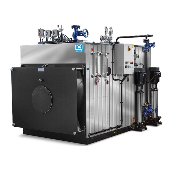
Page 7: Appliance Description
Drawing, legend and data refer to standard models. For specific models refer to the supplied accessory manual. For practical needs, the electric panel for models SIXEN 350÷800 vers. IT and SIXEN 350÷1350 vers. EXP is installed on the left, while for models SIXEN 1000÷5000 vers. -
Page 8: Dimensions And Connections
DIMENSIONS AND CONNECTIONS Mod. 2500÷5000 Dimensions SIXEN Description u.m. 1000 1350 1700 2000 2500 3000 3500 4000 5000 1825 1825 1930 1943 2150 2150 2300 2300 2460 2540 2710 2850 2970 1340 1340 1460 1460 1670 1670 1830 1830 1990 1990 2180 2300... -
Page 9: Technical Data
TECHNICAL DATA SIXEN DESCRIPTION u.m. 1000 1350 1700 Effective rated 1158 Thermal capacity 1022 1287 Efficiency at 100% (ref. P.C.I.) Pressure drops on exhaust side mbar Rated pressure 12/15 12/15 12/15 12/15 12/15 12/15 12/15 bar (12 bar version) 8 - 11,5 Min-max operating pressure bar (15 bar version) 12 - 14... -
Page 10: Burners
BURNERS SIXEN The burners that can be installed on the boilers must be CE marked according to European Directives: – Gas Directive 2009/142/EC – Electromagnetic Compatibility Directive 2014/30/EU – Low Voltage Directive 2014/35/EU – Machinery Directive 2006/42/EC (for liquid fuel burners) They must also be able to operate on boilers with flame inversion combustion chamber. -
Page 11: Paperwork
PAPERWORK These generators, supplied in single-block, are CE marked according to the Directive 2014/68/EU "PED". The documentation supplied with the generator is: – declaration of conformity of the whole – use and maintenance manual (always housed in the electrical panel) –... -
Page 12: Components
COMPONENTS SIXEN steam generators are equipped with a set of components that can be divided into: – Safety components (safety valves, safety level switches, safety pressure switch). – Indicator components (level indicator, pressure gauge, flame warning light). – Adjustment components (level regulators, pressure switches, pressure transmitters). –... - Page 13 The main components of the safety valve are: Lifting lever Spring Valve body Drain Fluid inlet IMPORTANT Before starting the generator, remove the steel wire that blocks the lever during transport. Make sure that the lifting lever is free to move. In case of conveyed drain, bracket the conveying pipe to compensate the reaction force generated when the fluid is drained.
- Page 14 VALVE MAINTENANCE The valve is a very delicate mechanism, so the system operator must check its efficiency. If necessary, contact a technician authorised by the manufacturer. It is good practice for the safety valves installed to protect the plant: – to be operated (once a week) with system pressurised, by activating the manual lifting lever of the shutter –...
-
Page 15: Level
Intrinsic safety operation for increasing pressure The figure shows a section of the intrinsic safety bellows for increasing pressure. When pressure increases, the contact lever interrupts the connection between terminals 1 and 2. Should the internal bellows pierce, the pressure will be sent to the external bellows. The external bellows surface is three times higher than the one of the internal bellows. -
Page 16: Installation
With these valves you can periodically test the efficiency of the level control system by performing the following operations. Open the purge valve for a few seconds and close it again. If the water disappears and then quickly returns to the starting point with large swings, it can be assumed that the level works well. Whereas, if the water slowly returns or stops at a different point from the previous, it means that one of the communications is obstructed;... -
Page 17: Product Receipt
Installation PRODUCT RECEIPT SIXEN generators are supplied complete with accessories. The combustion chamber contains: – turbulator unit to be inserted in the smoke pipes during installation – thermoceramic material to be inserted in the gap between burner mouthpiece and door insulation The control panel contains the following documentation: –... -
Page 18: Handling
HANDLING SIXEN steam generator must be handled using means adequate to the size and weight of the appliance, using the provided lifting eyebolts. ATTENTION The Personal Protective Equipment required by current legislation must be used. Installation... -
Page 19: Installation Room
INSTALLATION ROOM POSITIONING SIXEN boiler installation room must be for exclusive use, meet the Technical Standards and Legislation in force and equipped with adequately sized ventilation openings. It is recommended to position the boiler, if possible, lifted from the floor to minimise dust extraction by the burner fan. For information only, below is some useful information: –... -
Page 20: System Cleaning
The air must be filtered with 25 µm mesh. IMPORTANT ICI CALDAIE S.p.A. is not liable for any harm to people, animals or property damage caused by errors in the choice of components or in the construction of the plant. -
Page 21: Front Door Opening
DOOR OPENING REVERSAL (TO THE RIGHT) IMPORTANT Door opening inversion is possible ONLY for models from SIXEN 350 to SIXEN 1400. NOTE The ferrules (8) can be "adjusted with wrench" or "perforated for lever adjustment". -
Page 22: Front Door Adjustment
FRONT DOOR ADJUSTMENT DANGER Incorrect door adjustment with consequent damage to people and property voids the warranty conditions. DOOR ADJUSTMENT (OPENING ON THE RIGHT) VERTICAL ADJUSTMENT To make the adjustment: – with the door ajar, loosen the counter-nuts (1) of the hinge units –... -
Page 23: Burner Assembly
Technical Standards and the local and national Legislation. [1] For practical needs, the electric panel for models SIXEN 350÷800 vers. IT and SIXEN 350÷1350 vers. EXP is installed on the left, while for models SIXEN 1000÷5000 vers. IT and SIXEN 1700÷5000 vers. -
Page 24: Loading And Supply Of The Generator/System
LOADING AND SUPPLY OF THE GENERATOR/SYSTEM The steam generator is fed with a multistage centrifugal pump. The water must reach the pump intake with a certain head in order to avoid cavitation. The minimum temperature of the sucked water must be greater than 60°C; this favours the elimination of oxygen which, in any case, must be completely eliminated with suitable chemicals. -
Page 25: Water Characteristics
WATER CHARACTERISTICS The values in the following tables are extracted from tables 5.1 and 5.2 in EN 12953-10 (requirements concerning the quality of water supply and the water in the generator). Even for generators that are not covered by the aforementioned provision it is however necessary to adopt at least the indicated limits and however, to refer to the specialised companies that manage selecting the type of treatment to be carried out on the basis of a thorough analysis of the water available. -
Page 26: Frequency Of Analysis
5.2 Operating water - threshold values Steam generator water with pressure up to 20 bar CHARACTERISTICS u.m. Direct conductivity of the supply water > 30 μS/ Direct conductivity of the supply water ≤30 μS/ Appearance Clear, limpid, without foam or suspended solids Direct conductivity at 25°C μS/cm <... -
Page 27: Preliminary Checks
PRELIMINARY CHECKS IMPORTANT – Before starting the steam generator, it is advisable to perform " Alkaline boiling " with subsequent passivation, to remove any processing residues. Considering the high risk deriving from incorrect chemical treatments, the operations must be professionally qualified personnel carried out by –... -
Page 28: Checks After Commissioning
CHECKS AFTER COMMISSIONING With cold start, check that: – the generator is filled with water up to the minimum level – the volume increase due to heating (thermal expansion of the water) does not excessively increase the level making draining necessary at regular intervals to bring the level back to half scale of the glass indicator –... -
Page 29: Periodic Verifications
Maintenance Periodic maintenance is an obligation required by the safety Legislation and duration of the appliance, and it must only be entrusted to professionally qualified personnel. The frequency of the operations is shown in the specific paragraph. IMPORTANT Before performing any maintenance or cleaning: –... -
Page 30: Methods For Checking The Safety Devices
T(1) Physical verification of the intervention of the devices (as described in the following paragraph "Checking of the minimum level safety level switches"). T(2) Physical verification of the intervention of the devices (as described in the following paragraph "Checking of the minimum level safety level switches"). -
Page 31: Routine Maintenance
Failure") of 8 YEARS. It is an average time before a dangerous failure occurs. Therefore, they must be replaced after this operating period. We recommend replacing the probes once a year. To be evaluated, during cleaning/maintenance, the other mechanical, electromechanical and electronic parts. – The faulty components must be replaced with ICI CALDAIE S.p.A. original components. Maintenance... -
Page 32: Any Anomalies And Remedies
Incorrect connection to the electrical panel See the wiring diagram PROTECTING THE ENVIRONMENT ICI CALDAIE S.p.A. Protection and respect for the environment is a fundamental principle for ICI CALDAIE The quality of products, lower costs and protection of the environment are of equal importance for the company. - Page 33 Once registered, authenticate your e-mail address by clicking on the link that will be sent by e-mail to the provided inbox. ICI CALDAIE S.p.A. An additional e-mail will then be received with the credentials to access all services specifically developed by for those who will register their boiler through the QR Code.
-
Page 34: Available Accessories
SIXEN The accessories listed below are or can be installed on the generators. ICI CALDAIE S.p.A. For further details see the catalogue, at the Section INDUSTRIAL LINE – ACCESSORIES AND COMPONENTS. When requested at the time of ordering the generator, they are installed on the appliance before delivery. -
Page 35: Sixen
Authorities to certify the safety of the system, with the timing of the case. The user remains responsible for complying with the provisions of M.D. 329/2004 regarding commissioning (COMMISSIONING REPORT). Applicable on steam generators (BX 60÷600)-(BNX 100÷1000)-(SIXEN 350÷2000)-(GSX 350÷2000). ATTENTION The GSS 72/1 system can only be applied to boilers with boiling pressure of 12 bar or less. -
Page 36: Sixen
Self-checking high level safety kit This system ensures that the level in the boiler does not exceed the allowed value thus avoiding flood problems. It consists of a "fail safe" probe connected to an electronic level relay with self-checking feature, capable of indicating: –... -
Page 37: Sixen
Notes Notes... -
Page 38: Sixen
Notes... -
Page 39: Sixen
Notes... - Page 40 ICI CALDAIE SpA 37059 Fraz. Campagnola di Zevio ( Verona) Italy Via G. Pascoli 38 Phone: +39 0458738511 Fax:+39 0458731148 info@icicaldaie.com www.icicaldaie.com...
Need help?
Do you have a question about the SIXEN 350 and is the answer not in the manual?
Questions and answers