Advertisement
Quick Links
INSTALLATION & SERVICING MANUAL
Models covered by these instructions
C80FF
C95FF
THE HENRAD
C80 FF
the combi boiler
C95 FF
the combi boiler
Wall mounted, gas fired fanned flue combination boiler
CE certified P.I.N. No. 0063AQ6877
Destination Countries GB, IE.
(47-348-05) HENRAD C80FF
(47-348-06) HENRAD C95FF
Advertisement

Subscribe to Our Youtube Channel
Related Manuals for Ideal Boilers Henrad C80FF


Summary of Contents for Ideal Boilers Henrad C80FF
- Page 1 INSTALLATION & SERVICING MANUAL Models covered by these instructions C80FF (47-348-05) HENRAD C80FF C95FF (47-348-06) HENRAD C95FF THE HENRAD C80 FF the combi boiler C95 FF the combi boiler Wall mounted, gas fired fanned flue combination boiler CE certified P.I.N. No. 0063AQ6877...
- Page 2 NOTE: TO THE INSTALLER: leave these instructions adjacent to the gas meter GENERAL CONTENTS Boiler Water Circuit Diagram Boiler Dimensions, Services & Clearances Gas Safety (Installation And Use) Regulations, 1994, And Amendments 1996 Air Supply Flue Installation Requirements Water Circulation System Water Treatment Electrical Supply Sealed System Requirements Central Heating...
- Page 3 Electrical Connections Pictorial Wiring Functional Flow Diagram Initial Lighting Commissioning And Testing Servicing Fault finding Short list of parts INTRODUCTION C80FF and C95FF are wall mounted, low water content, balanced flue combination gas boilers of type C intended for use with gas group Central heating (CH) output and domestic hot water (DHW) output are both fully modulating: –...
- Page 4 Table 1 – General Data C80FF C95FF Gas supply type & connection 2H – G20 – 20 mbar, 22 mm copper Inlet connection – Domestic Hot Water 15 mm copper Outlet connection – Domestic Hot Water 15 mm copper Flow & return connection – Central Heating 22 mm copper Flue terminal diameter mm (in.)
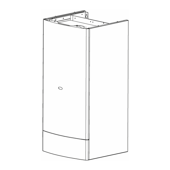
- Page 5 C80FF C95FF Boiler size Height mm (in.) 850 (33 1/2) Width mm (in.) 400 (15 3/4) Depth mm (in.) 370 (14 9/16) Lift weight kg (lb.) 38 (84) Table 2 – Performance Data – Central Heating C80FF C95FF Burner pressure (HOT) mbar (in.w.g.) 9.5 (3.8) 1.4 (0.6)
- Page 6 Front clearance The minimum front clearance when built in to a cupboard is 5mm (1/4″) from the cupboard door but 450mm (17 3/4″) overall clearance is still required, with the cupboard door open, to allow for servicing. See Table Table 4 Clearances LH side 15 mm (1/2″)
- Page 7 Pipe size O.D. mm CH flow CH return Gas inlet DHW cold inlet DHW hot outlet SAFETY Gas Safety (Installation and Use) Regulations, 1994, and amendments 1996 or rules in force It is law that all gas appliances are installed and serviced by a CORGI registered installer (identified by) in accordance with the above regulations. Failure to install appliances correctly could lead to prosecution.
- Page 8 The Electricity at Work Regulations, 1989. The manufacturers notes must NOT be taken, in any way, as overriding statutory obligations. IMPORTANT: These appliances are CE certificated for safety and performance. It is, therefore, important that no external control devices, e.g. flue dampers, economisers etc., are directly connected to these appliances unless covered by these Installation and Servicing Instructions or as otherwise recommended by Caradon Plumbing Ltd.
- Page 9 FLUE INSTALLATION REQUIREMENTS The flue must be installed in accordance with the recommendations of BS. 5440: Part 1. The following notes are intended for general guidance: 1 The boiler MUST be installed so that the terminal is exposed to external air. 2 It is important that the position of the terminal allows the free passage of air across it at all times.
- Page 10 WATER TREATMENT Antifreeze fluid, corrosion and scale inhibitor fluids suitable for use with boilers having copper heat exchangers may be used in the central heating system. For further information contact either: Fernox Fry Technology UK Tandem House Marlow Way Beddington Farm Road Croydon CR0 4XS Tel 0870 601 5000 Betz Dearborn Ltd...
- Page 11 a. Circulating pump. b. Safety valve; with a non–adjustable pre–set lift pressure of 3 bar (45lb/in c. Pressure gauge; covering a range of 0–4 bar. d. 8 litre expansion vessel; with an initial charge pressure of 0.7 bar (10.5 lb/in For further details refer to BS.5449:1 and the British Gas Corporation publication ‘Specifications for Domestic Central Heating and Hot Water’.
- Page 12 For expansion volumes see Table Guidance on vessel sizing is given in BS 7074:1 and BS 5449 5 SEALED SYSTEM REQUIREMENTS central heating (continued) 7 Thermostatic radiator valves. Caradon Plumbing Ltd. support the recommendations made by leading manufacturers of domestic heating controls that heating systems utilising full thermostatic radiator valve control of temperature in individual rooms should also be fitted with a room thermostat controlling the temperature in a space served by radiators not fitted with such a valve as stated in BS5449.
- Page 13 5 When connecting to suitable showers, i.e. those designed for modulating domestic hot water, ensure that: a. The cold inlet to the boiler is fitted with an approved anti–vacuum or syphon non–return valve. b. Hot and cold supplies are of equal pressure. 6 Hard water areas In areas where the water is ‘hard’...
- Page 14 The boiler is supplied fully assembled in one pack A, together with a standard flue assembly for lengths up to 600 mm, rear or side flue outlet, in pack B. Unpack and check the contents. Pack A contents The boiler. These installation &...
- Page 15 9 PACKAGING To unpack the boiler refer to the instructions on carton end flap. 10 DETERMINING THE FLUE LENGTH AND FLUE PACKS REQUIRED The maximum total equivalent horizontal flue length is: 3 m for model C80FF 1.85 m for model C95FF. For the number of Extension Ducts required see the Flue kit requirements table below.
- Page 16 Rear flue mounting cut flue to length: for C80FF C+185=D C+7 1/4″ =D for C95FF C+160=D C+ 6 3/8″ =D Having cut length D mark around the end of the air duct 10 mm from the cut end then cut the air duct only to be 10 mm shorter than the flue duct to allow for engagement.
- Page 17 Flue kit requirements Total length of flue Extra packs required 600 mm (23 5/8″) None ∗ 1550 mm (61″) One pack D ∗ 2500 (98 7/16″) Two pack D ∗ 3000 (118 1/8″) Three pack D ∗ Pack B – supplied as standard Pack D –...
- Page 18 13 WALL MOUNTING TEMPLATE (side flue) IMPORTANT: 1 Tape the template into the selected position. 2 Ensure squareness by hanging a plumbine. 3 Mark onto the wall the following: a. the wall mounting plate screw position b. Extended the centre line as shown. Mark the flue ductcentre from the corner (see diagram and template) c.
- Page 19 NOTE: If the teminal is to be sited within 25 – 40 mm of a corner or vertical pipe (refer to Table 6) then the hole MUST be accurately cut and the rubber weather seal trimmed around the groove provided. (The terminal wall plate cannot be fitted close to a corner).
- Page 20 17 FITTING THE FLUE Pass the cut flue through the prepared hole, ensuring that the groove is uppermost. 18 MOUNTING THE BOILER In order to ensure the boiler front panel Is not damaged during boiler mounting, remove the bottom panel (2 screws A) and the boiler front panel by opening the door and removing the two fixing screws B.
- Page 21 19 CONNECTING THE TURRET TO THE BOILER 1 Fit the Elbow–Boiler gasket on the boiler. 2 Fit internal sealing gasket. 3 Fit the duct–elbow sealing gasket on the turret so that the edge of the gasket coincides with the edge of the duct. 4 Fit the flue duct gaskets on the gasket seats of the flue turret directing the lips of the gaskets as shown.
- Page 22 21 FLUE EXTENSION DUCT PACK D CONTENTS Use a maximum of: 2 extension ducts on model C95FF 3 extension ducts on model C80FF 22 ASSEMBLING THE EXTENDED FLUE 1. Remove the cardboard support aid from the flue and place safely to one side. 2.
- Page 23 23 CUTTING THE FLUE TO LENGTH 1. Check the flue length measurement made in Frame 2. Use this dimension to mark the flue length, starting from the groove, as illustrated. 3. To ensure a square cut, mark the flue all the way round, using, e.g. a steel tape or paper strip with the ends overlapped. 4.
- Page 24 25 CONNECTIONS Fit the service valves washers and tail pipes as shown. Connect to the tail pipes by proprietory fittings. The pipework may be directed up, down or through the rear wall as required. To allow for any future removal of the boiler it is suggested that union joints be incorporated into the upward pipework. See additional illustration for upward pipework routing...
- Page 25 26 SAFETY VALVE DRAIN The discharge pipe should be positioned so that the discharge of water or steam cannot create a hazard to the occupants of the premises or damage to electrical components and wiring. The discharge pipe shall be 15 mm copper and connected using the nut and olive in the hardware pack. The suggested routing of the pipe is shown in the following drawing.
- Page 26 NOTE: Ensure that the lengths of the current conductors are shorter than the earth conductor so that if the cable slips in its anchorage the current carrying conductors become taut before the earth conductor. 29 PICTORIAL WIRING...
- Page 27 30 FUNCTIONAL FLOW DIAGRAM...
- Page 28 31 EXTERNAL ELECTRICAL CONTROLS Wiring external to the boiler MUST be in accordance with the current I.E.E. (BS.7671) Wiring Regulations. The fuse rating should be 3A. Optional Programmer Kits These are supplied in either digital or analogue options, each with the relevant instructions. External Programmers This should be of the single channel type (as this boiler does not incorporate a pre–heat facility for the istantaneous hot water service).
- Page 29 Diagrams B & C show applications to boilers fitted with alternative time controls. Designation of the terminals will vary but the programmer and thermostat manufacturers' leaflets will give full details. NOTE: If the boiler is installed in a garage it may be necessary to fit a pipe thermostat, preferably on the return pipework. Earths are not shown for clarity but must never be omitted.
- Page 30 IMPORTANT: Before lighting the boiler you should note especially that: 1 Check that all the drain cocks are closed and any valves in the flow and return are open. 2 Check that the system has been filled and pressurised and that the boiler is not air locked. 3 Check that the overheat thermostat (D) is calling for heat –...
- Page 31 8 Set the main switch (A) to ‘ON’. Following a pre–purge period the gas control solenoid valve should open and the spark commence, continuing until the burner is established. 9 Check that the burner lights smoothly. If this does not occur within 20 seconds, turn the on/off switch to OFF, wait for 5 seconds then try again. If the burner still does not light, refer to the ‘Fault Finding’...
- Page 32 2 Open DHW tap. 3 Observe ignition burner pressure during 10 sec. ignition period (4 mbar); adjust the pressure if necessary using the “wheel” on the ignition module indicated in the following drawing. If the burner extinguishes press the reset button and the burner will re–light. 4 Close the DHW tap 5 Re–connect the detection lead Minimum valve setting...
- Page 33 ALWAYS carry out the preliminary electrical system checks, i.e. earth continuity, polarity, resistance to earth and short circuit, using a suitable test meter. B. Gas Installation 1. The whole of the gas installation, including the meter, should be inspected and tested for soundness and purged in accordance with the recommendations of BS.
- Page 34 5. Advise the user of the precautions necessary to prevent damage to the system and to the building, in the event of the system remaining inoperative during frosty conditions. 6. If a programmer kit is fitted, draw attention to the Programmer Kit User's Instructions and hand them to the householder. 7.
- Page 35 DO NOT OPERATE THE BOILER IF THE SEALING PANEL IS NOT FITTED. 38 BOILER INNER CASE COVER REMOVAL 1 Turn off the gas supply at the gas service cock and disconnect the electricity supply. 2 Remove the screws A indicated and lift off the boiler front panel. 3 Loosen the screws B and lift off the right hand panel.
- Page 36 5 Check that the impeller runs freely. Clean with a soft brush or renew as necessary. Refer to frame 53 for replacement. NOTE: Always take care when handling the fan, in order to preserve the balance of the impeller. 40 BURNER REMOVAL AND CLEANING 1 Remove the inner case cover as explained in frame 2 Undo the four screws A and remove the combustion chamber panel B.
- Page 37 7 Inspect the spark and detection electrodes. Ensure they are clean and in good condition; repalce if necessary. 8 Check the spark electrodes gap is correct. 9 Check that the spark and detection electrodes leads are in good condition and renew as necessary. 41 CLEANING THE HEAT EXCHANGER 1.
- Page 38 After any servicing, reference should be made to: Table 2 Table 3 (or the data plate) which quote details of the burner pressures. If the burner pressures are incorrect ensure the inlet pressure, with the appliance running, is correct (refer Table If the burner pressures require adjustment refer to frame 33...
- Page 39 47 SPARK AND DETECTION ELECTRODE REPLACEMENT 1. Disconnect the electrical supply. 2. Remove the boiler front panel, the right hand panel and the inner case cover. Refer to frame 3. Open the combustion chamber and disconnect the electrodes leads from the ignition pcb. 4.
- Page 40 49 BURNER REPLACEMENT 1. Remove the inner case cover as explained in frame 2. Undo the four screws A and remove the combustion chamber panel B. 3. Disconnect the electrodes leads from the ignition pcb. 4. Undo the four screws placed at the right and left sides of the burner and extract it taking care not to damage the electrodes. 5.
- Page 41 5. Disconnect the pressure sensing pipe A from the gas valve. 6. Unscrew the eight Allen key screws B and remove the valve. 7. Fit the new gas valve in reverse order ensuring new gaskets are fitted. 8. Check the operation of the boiler. 52 WATER PRESSURE GAUGE REPLACEMENT 1 Disconnect the electrical supply.
- Page 42 3 Disconnect the electrical harness from the fan. 4 Disconnect the pressure sensing pipe A from the fan noting which spigot on the fan venturi it was fitted to. 5 Undo the fixing screws B and remove the fan. 6 If the plastic venturi is fitted to the fan in position C, carefully remove it from the old fan and fit it to the replacement in the same position as before. 7 Fit the new fan and reassemble in reverse order.
- Page 43 55 MAIN CONTROL PCB REPLACEMENT 1 Disconnect the electrical supply. 2 Gain access to the controls area by removing the boiler front panel. (refer to frame 38), remove the boiler bottom panel (held with 2 screws) and lower the control panel. 3 Squeeze the protective cover sides to disengage from the front panel and remove it.
- Page 44 5 Release system pressure by opening the main circuit drainage cock. Do not release CH pressure using the pressure relief valve. It may cause debris within the system to foul the valve. 6 Undo the screw A, remove the cover of the terminal box. 7 Loosen the cable holder B and disconnect the power supply wiring from the terminal block C.
- Page 45 Two different sizes of flow limiter are available. Table 8 Nominal flow rate (litres/min) Colour Blue 58 PRIMARY HEAT EXCHANGER REPLACEMENT 1 Disconnect the electrical supply. 2 Remove the inner case cover as explained in frame 3 Close off the isolating cocks of the CH circuit at the bottom of the boiler. 4 Release system pressure by opening the main circuit drainage cock.
- Page 46 3 Close off the isolating cocks of the CH and DHW circuits at the bottom of the boiler. 4 Release system pressure by opening the main circuit drainage cock. Do not release CH pressure using the pressure relief valve. It may cause debris within the system to foul the valve. 5 Release the pressure of the DHW circuit by opening a hot tap.
- Page 47 2 Gain access to the controls area by removing the boiler front panel. (refer to frame 38), remove the boiler bottom panel (held with 2 screws) and lower the control panel. 3 Close off the isolating cock of the DHW circuit at the bottom of the boiler. 4 Release the pressure of the DHW circuit by opening a hot tap.
- Page 48 2 Gain access to the controls area by removing the boiler front panel. (refer to frame 38), remove the boiler bottom panel (held with 2 screws) and lower the control panel. 3 Close off the isolating cocks of the CH circuit at the bottom of the boiler. 4 Release system pressure by opening the main circuit drainage cock.
- Page 49 For option B, proceed as follows: 1. Disconnect the electrical supply. 2. Gain access to the controls area by removing the boiler front panel and the right hand panel (refer to frame 38), remove the boiler bottom panel (held with 2 screws) and lower the control panel. 3.
- Page 50 67 HOT WATER MODE FAULT FINDING WARNING: Care must be taken when conducting fault finding tests to guard against the risk of electric shock NOTE: 230vac is the nominal UK supply voltage this may vary between 253vac and 196vac When checking continuity ensure the power is off to the appliance Re–connect power to continue fault finding The reference “X3″...
- Page 51 68 HEATING MODE FAULT FINDING WARNING: Care must be taken when conducting fault finding tests to guard against the risk of electric shock NOTE: 230vac is the nominal UK supply voltage this may vary between 253vac and 196vac When checking continuity ensure power is off to the appliance –...
- Page 52 the code of practoce for the installation commissioning & servicing of central heatsystems Caradon Plumbing Limited, P.O. Box 103, National Ave, Kingston upon Hull, HU5 4JN. Telephone: 01482 492 251 Fax: 01482 448 858. Registration No. London 322 137. Caradon Plumbing Limited pursues a policy of continuing improvement in the design and performance of its products. The right is therefore reserved to vary specification without notice.
- Page 53 Installer/Technical Helpline: 01482 498 663...
Need help?
Do you have a question about the Henrad C80FF and is the answer not in the manual?
Questions and answers