
Related Manuals for Axxeron HESCH HE 5731


Summary of Contents for Axxeron HESCH HE 5731
- Page 1 HE 5731 Compact / Modular Solenoid valve controller (Figures are similar) Operating instructions (English translation German original version) # 373344 | Version 1.10...
- Page 2 Editor: AXXERON HESCH electronics GmbH, Documentation Department Copyrights © Copyright 2024 AXXERON HESCH electronics GmbH. All rights reserved. The content including pictures and the design of these operating instructions are subject to copyright protection and other laws for the protection of intellectual property. The operating instructions may only be distributed as a complete document and only with reference to the source.
- Page 3 Table of Content LEGAL PROVISIONS ........................... 5 SAFETY INFORMATION ..........................6 2.1....................... 6 YMBOLS AND ASIC AFETY NSTRUCTIONS 2.2............................. 6 IGNAL WORDS 2.3....................7 AFETY IN THE INDIVIDUAL OPERATING PHASES 2.4..........................8 EVICE IDENTIFICATION TECHNICAL DATA ............................ 10 DEVICE DESRIPTION ..........................
- Page 4 Legal provisions Document History Date/ Version Description Author 04.10.2018 / 1.0 Translation Modification of name plate for solenoid valve control and 12.12.2018 / 1.1 control unit Chapter Electrical Commissioning: Note added for enter- 15.08.2019 / 1.2 ing password prior to commissioning. Chapter 5 Electrical Commissioning: Note for entering password deleted, Chapter 5.2 Readout and set password: added...
- Page 5 Safety Information 1. Legal provisions Manufacturer AXXERON HESCH electronics GmbH, Boschstraße 8, 31535 NEUSTADT, GERMANY. Intended Use The solenoid valve controller HE 5731 is used for cleaning industrial filter sys- tems. The number of valves is from 1 to a maximum of 64, and can be scaled, using modular extension units.
- Page 6 Safety Information 2. Safety Information 2.1. Symbols and Basic Safety Instructions This chapter contains important safety regulations and notes. To protect against personal injury and material damage, it is necessary to read this chapter carefully before working with the device. Symbols used The following symbols are used in this manual.
- Page 7 Safety Information 2.3. Safety in the individual operating phases When installing the control unit and during operation, the following safety instructions must be observed. Danger of Electrocution! Before working on the device, switch off all power supplies used. The electrical cables must be laid according to the respective national regula- tions (in Germany VDE 0100).
- Page 8 Safety Information Troubleshooting! At the beginning of troubleshooting, all possible sources of faults on addi- tional devices or supply lines (measuring lines, wiring, downstream de- vices) should be taken into consideration. If the fault was not found after checking these points, we recommend sending the device to the supplier. Decommissioning! Switch off the power supply on all poles if the device is to be decommis- sioned.
- Page 9 Technical data The following special regulations must be observed: Connect cables professionally in glands. Close not needed housing bores with locking bolts. The ATEX approval remains valid only if the installation is carried out pro- fessionally in compliance with the protection class specified in the device identification.
- Page 10 Technical data 3. Technical data Intended use: Solenoid valve controller for cleaning industrial filter systems Models: HE 5731 in compact housing as master controller with 16 valve outputs maximum HE 5731 operating unit as control panel built-in casing (the valve outputs are located on the control unit) ...
- Page 11 Technical data Climatic ambient conditions Storage - 20°C…+ 70°C - 25°C…+ 85°C Transport Operation Compact housing -20°C…+50°C in EX zone 22: -20°…+40°C Modular -20°C…+50°C -not suitable for EX zones Relative humidity ≤ 95% annual average, Relative humidity climatic conditions in accordance with 3K6 to DIN EN 60721-3 with restriction, outdoor installation only with protective roof.
- Page 12 Device desription 4. Device desription 4.1. HE 5731 Compact HE 5731 (Compact) (figure is similar) HE 5731 (Compact) Connections (figure is similar) HE 5731 E extension unit (figure is similar) HE 5731 Operating instructions # 373344, Version 1.10...
- Page 13 Device desription 4.1.1. HE 5731 Modular The operating unit HE 5731 can be installed with a distance of up to 100 metres away from the control unit. The operating unit itself has no valve outputs. The valve outputs are located on the control unit (see Figure 6 and Figure 7). Operating and control unit are connected with a patch cable (Cat5 or higher).
- Page 14 Device desription HE 5731 Control unit The control unit for standard rail mounting has 16 valve outputs maximum. 4 control units maximum can be connected to the operating unit (see also chapter 6.3). Figure 6 shows the control unit where external display devices are connected via a connection adapter (see chapter 10 Options).
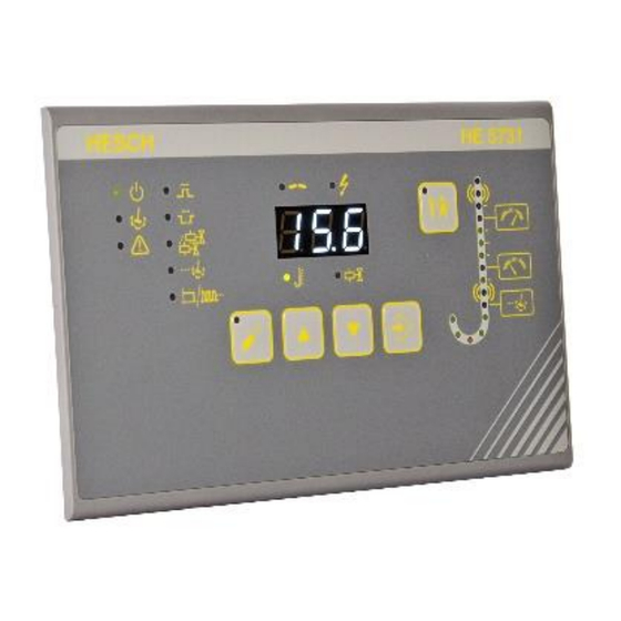
- Page 15 Device desription 4.2. Display and Operating Elements HE 5731 Display and Operating Elements Symbols Meaning Operation signal Cleaning active Alarm active Pulse time Break time The number of valves is shown in the display and can be changed Post-cleaning cycles are shown in the display and can be changed Total / partial cycle is shown in the display and can be changed Interruption due to defective valve line or solenoid valves Short circuit of a valve line (overcurrent)
- Page 16 Device desription Symbols Meaning PARA key: parametrisation mode On/Off UP key: increase the displayed value DOWN key: decrease the displayed value ENTER key: Confirm the displayed value TEST key: Test mode On/Off Display Normal operation: current differential pressure, current valve ...
- Page 17 Installation 5. Installation Note! If you want to drill the device to the wall, Figure 10 can be used as a drill- ing template. The ambient temperature at the installation point must not exceed the permissible temperature for nominal use specified in the technical data. Note! If the device version Compact, according to nameplate, is suitable for EX zone 22, you must strictly observe the safety notes for explo-...
- Page 18 HE 5731 Operating instructions #373344 Note! Upon receipt, check the delivery for completeness and visible defects. In the event of a complaint, contact your responsible representative of AXXERON HESCH electronics GmbH immediately. HE 5731 Operating instructions # 373344, Version 1.10...
- Page 19 Installation 5.2. Torques Note! When mounting the device, you must strictly observe the torques given in the following tables. 5.2.1. Cable glands Type Clamping range for cables Screw Dust thread/ cover Counter nut Gasket 1+2+3 Gasket 1+2 Gasket 1 Colour Min.
- Page 20 The housing lid can be opened to the left up to an angle of 105°. Optionally, the housing lid can be closed by 4 screws in addition, to protect it from unauthorised access. For further information, please contact your service representative of AXXERON HESCH electronics GmbH.
- Page 21 Electrical Commissioning 6. Electrical Commissioning Before switching on the device, observe the following: Danger of Electrocution! Electrical installation must only be carried out when the power is discon- nected. Danger of Electrocution! Work on the electronics may only be carried out by qualified personnel. Explosion prevention The HE 5731 Compact is suitable for use in explosion zone 22 with closed lid only.
- Page 22 Electrical Commissioning 6.1. Read out and set password Switch on the device while keeping both keys UP and DOWN pressed for 5 seconds. When the 5 seconds are up, "cod" is displayed and afterwards the currently set pass- word. In state of delivery, the pre-assigned password 001 is displayed (see also 7.2 Parameter table).
- Page 23 Electrical Commissioning HE 5731 Compact with 24 V DC supply voltage (connection adapter optional) (figure is similar) HE 5731 Compact with 24 V DC supply voltage (without connection adapter) (figure is similar) See name plate for supply voltage value (on the right of the housing). (There are devices with 100…240 V AC and devices with 24 V DC supply voltage).
- Page 24 Electrical Commissioning Connecting master device (24 V DC version) with extension unit (24 V DC) Connecting master device (100…240 V AC version) with extension unit (24 V DC) 6.2.2. Panel mounting housing The supply voltage is connected centrally at the control unit. The operating unit is con- nected to the 24 V DC supply via a patch cable (CAT 5 or better).
- Page 25 Electrical Commissioning 6.2.3. Communication Serial communication is enabled by connecting the “B” or “A” connections, from device to device. The coding switch provides the logical position in the sequence of the controls, which do not have to correspond to the cabling sequence. Caution! The lines B and A must not be interchanged.
- Page 26 Electrical Commissioning 6.3. Valve connections Valve connections (1-16) HE 5731 control unit (100…240 V AC) valve connections Note! All valve outputs of a system refer to the same ground (-). It is permitted to use one ground wire for multiple valves. Note! All valve outputs are short-circuit proof and are monitored for function.
- Page 27 Parametrisation 6.3.1. Coding switch Coding switch for the device order. The device number of the communication indicates the controlled order of valves, independent of the order of wiring. The device number “5“ is for the operating and control unit without effec- tive valve connection.
- Page 28 Parametrisation 7. Parametrisation Explosion Prevention! It is permitted to use the device version HE 5731 Compact (see Figure 1) in explosion zone 22 with closed lid. It is mandatory to ensure that no explosive ambient conditions, such as e.g. development of dust exist, be- fore opening the device for e.g.
- Page 29 Parametrisation 7.2. Parameter table Parameter Adjustment range Default Pre-assignment setting 0…999 Password 3-digit number that must be entered before parameters can be changed. 0 = no password protection Pulse time 0.01…9.99 s 0.10 s 0.10 s 1.0 s …999 s Break time 5.0 s 5.0 s...
- Page 30 Parametrisation Parameter Adjustment Default Pre-assignment range setting Lower threshold [mbar] OFF, 10.0 mbar 10.0 mbar 0.0…500.0 mbar (at 0…35 mbar If underrun, dp-dependent cleaning stops. measuring range) End of dp cycle 25.0 mbar (at 0…90 mbar measuring range) 130,0 mbar (at 0…450 mbar measuring range) Low-alarm [mbar]...
- Page 31 Parametrisation The following parameters can only be changed with the "EasyTool Controls" program: (see chapter 7.4 Parametrisation with Service PC) Parameter Adjustment range Factory Pre- setting assignment Delta-p filter Filter constant for damping the 0.1…10.0 s 2.0 s 2.0s Delta-p measurement. Delta-p working range Defines the working range below the upper threshold in % of the...
- Page 32 1. Connect the PC to the operating unit via USB cable. 2. Start "EasyTool Controls" to transfer the files or data. Note! Instructions for the most important program functions are available at AXXERON HESCH electronics GmbH. HE 5731 Operating instructions # 373344, Version 1.10...
- Page 33 Operation of the control 7.5. Enable / Disable Precoating Enable: Press the TEST key and the UP key simultaneously. “PrE” is displayed alternately with other information. Disable: Press the TEST key and the DOWN key simultane- ously. After reaching the first cleaning threshold (increased by the precoating), the precoating is automatically disabled.
- Page 34 Operation of the control 8. Operation of the control 8.1. Normal Operation Operation is started by applying the supply voltage. The valve cleaning is controlled via the inputs and outputs of the device. Note! All valve outputs of a system refer to the same mass (-). It is permitted to use one ground line for several inputs.
- Page 35 Operation of the control 8.2. Test Function Press the TEST key to perform a function test of the valves. Select the desired valve with the UP / DOWN keys. Press ENTER (The selected valve is permanently oper- ated with the stored pulse and pause time). If necessary, test the next valve.
- Page 36 Operation of the control 8.4. Differential pressure measurement External dis- External play device display device Differential pressure measurement (connection adapter optional) (figure is similar) External display device Differential pressure measurement (without connection adapter) (figure is similar) 2-wire sensors, such as HE 5409, HE 5410, HE 5421 with communication of the power signal to an external display device (see chapter 10 Options).
- Page 37 Error messages The time-controlled use of the controller despite the presence of a differential pressure input is as follows: By using a 5.6 kΩ resistor, a constant differential pressure signal is simulated. The HE 5731 now operates time-controlled according to setting. The use of the resistor creates a simulated measuring current of 4 mA.
- Page 38 Error messages 9. Error messages Display Cause Action “buS” is blinking in the The sum of the valves set on Check the set total valve display, the alarm LED the devices is smaller than number is illuminated the set total valve number Check the valve number set on the coding switch ...
- Page 39 Options Display Cause Action The permissible valve current Check the indicate valve The LED flashes. of 1 A has been exceeded for short-circuit The display shows the Check the valve in relevant valve question Check if the valve plug is connected correctly.
- Page 40 17–19. The connection adapter can be purchased at AXXERON HESCH electronics GmbH (article number # 57310089). This chapter only concerns devices that are designed to use an optional connection adapter.
- Page 41 Options Open the housing cover (see Figure 14). Put the connection adapter with the pin header onto the terminals 17-19. Connect the external device (see Figure 28). Close the housing cover. Connection adapter current input / output (article number # 57310089) (figure is similar) Note! If no external device is connected, the analogue output must be bridged.
- Page 42 Options Differential pressure measur- Device with differential or ing with galvanically separated ana- 2-conductor sensor, e.g.. logue input. Max. burden analogue output = 400 Ω. HE 5409, HE 5410 or HE 5421. Connection adapter / terminals HE 5731 Operating instructions # 373344, Version 1.10...
- Page 43 Options 10.2. Pressure switch Optionally, the enable input (EN) can be used for connecting a pressure switch for con- trolling the system. “ENABLE” is then without function at this input. Optional use of the pressure switch: The pressure switch (p) is used to control the mechanical valve function.
- Page 44 Disposal Dispatch metals and plastics for recycling. Electrical and electronic components must be collected separately and disposed of accordingly. Dispose of assembled printed circuit boards professionally. Service AXXERON HESCH electronics GmbH Boschstraße 8 31535 NEUSTADT GERMANY Phone: +49 5032 9535-0 Internet: www.hesch-automation.com...
Need help?
Do you have a question about the HESCH HE 5731 and is the answer not in the manual?
Questions and answers