
Related Manuals for Axxeron HESCH HE 5722


Summary of Contents for Axxeron HESCH HE 5722
- Page 1 HE 5722 Solenoid valve controller Operating Instructions (Original German version)
- Page 2 Editor: AXXERON HESCH electronics GmbH, Documentation Department Copyrights © Copyright 2023 AXXERON HESCH electronics GmbH. All rights reserved. The content including pictures and the design of these operating instructions are subject to copyright protection and other laws for the protection of intellectual property. The operating instructions may only be distributed as a complete document and only with reference to the source.
-
Page 3: Table Of Contents
Date: 16.03.2023 Art. No.: 372211 INSTRUCTION MANUAL HE 5722 General safety instructions Explosion protection General description Installation and connenction Installation of the equipment Fittings Operation Control and display elements Settings 3.2.1 Code Settings 3.2.2 Settings in the Main Parameters menu (HP) 3.2.3 Settings in the Valve Parameters menu (Ut) 3.2.4... - Page 4 Normal operation Test functions 10.1 Lamp test 10.2 Display inputs 10.3 Peak valve memory 10.4 Valve test 10.4.1 Single valve test 10.4.2 Endurance test 10.4.3 Current test Error messages 11.1 Fault LEDs 11.2 Acknowledging a fault 11.3 Power-up test and error messages Appendix Inputs Outputs...
-
Page 5: Instruction Manual He 5722
General Safety Instructions Safety of the unit This unit was built and tested in accordance with the manufacturing documents. It left the factory safety-tested and in perfect condition. It complies with the safety class specified in the Instruction Manual. All information and warnings contained in these safety instructions must be observed, in order to preserve this condition and guarantee safe operation. - Page 6 General Safety Instructions Electrical connections All electrical wiring should be laid in accordance with the relevant EMC standards as well as any nationally valid regulations (VDE 0100 in Germany). Measuring lines should be laid separately from signal and power lines. The protective conductor terminal (inside the instrument rack) must be connected to a protective earth conductor.
- Page 7 General Safety Instructions Removal from service If the unit must be removed from service, all poles of the power supply must be disconnected. Steps must be taken to prevent the unit from being started up again inadvertently. If the unit is interconnected with other units and/or equipment, you should consider the potential consequences prior to switching it off and take appropriate precautions.
-
Page 8: Explosion Protection
Explosion Protection E Explosion protection Units with the following marking are suitable for use in explosion one 22. II3D °C IP65 Marking: The IP65 protection class forms part of the Ex marking. As a result, the following rules must be observed: Lines must be expertly connected using suitable fittings in order to ensure compliance with the protection class. -
Page 9: General Description
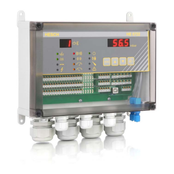
General Description 1 General description The HE 5722 filter controller is used to measure differential pressure and to pulse magnetic valves of the kind encountered in industrial dust removing applications. The use of an MB90F347 microprocessor facilitates flexible selection of functions and extensive monitoring functionality. -
Page 10: Installation And Connenction
Installation and Connection 2.1 Installation of the equipment The unit should be installed in such a way that it is protected against moisture and fouling. Conformity with the approved ambient conditions must be ensured. The electrical connections must comply with the relevant VDE specifications as well as any locally valid regulations. - Page 11 Installation and Connection 2.3 Electrical connections Terminals Spring-loaded PCB terminals, max 15 A, max. 1.5 mm core cross-section, rigid / flexible. Infeed The valve controller can be operated with 115 V AC (± 10%), 230 V AC (± 10%) or 24 V DC (±...
- Page 12 Installation and Connection 2.4 Ambient conditions Ambient temperature Operation 0 to +50°C Storage -25 to +70°C Transport -25 to +70°C Climatic category KUF to DIN 40040 Relative humidity: 75% (annual average), no condensation allowed Air pressure Operation and storage 80 kPa to 106 kPa Transport 70 kPa to 106 kPa Condensation...
-
Page 13: Operation
Operation 3 Operation 3.1 Control and display elements Valve display: This 2-digit, 7-segment display indicates the current valve or the faulty valve. The name of the submenu is shown in the parameter settings mode. ∆p display: This 4-digit, 7-segment display indicates the current actual value. -
Page 14: Settings
Operation Cleaning: LED lights up while the filter is being cleaned. Pulse LED: LED lights up when a valve is actuated. 17-18 Valve error: • LED flashes if the valve current is interrupted (< 15 mA). • LED flashes to indicate valve overcurrent (> 1.2 A). LEDs 11, 12 and 17 to 18 light up continuously if the controller detects that the cause of a fault has been cleared but the fault signalling relay is programmed with a HOLD function. -
Page 15: Settings In The Main Parameters Menu (Hp)
Operation 3.2.2 Settings in the Main Parameters menu (HP) Parameter Meaning Setting range Default setting No. of valves 01 - 24 PuLS Pulse time 00.01 - 99.99 s PAuS Interval time 000.1 - 999.9 s u.Sch Low threshold -10.0 - 500.0 mbar o.Sch High threshold -10.0 - 500.0 mbar... -
Page 16: Settings In The Delta P Parameters Menu (Dp)
Operation 3.2.4 Settings in the Delta P Parameters menu (dP) Parameter Meaning Setting range Default setting HI - Lo S.AL1 Switching mode, alarm 1 Maximum / minimum H.AL1 Hysteresis, alarm 1 0.1 - 500.0 mbar d.AL1 Delay, alarm 1 0:00 - 99:59 hh:mm HI - Lo S.AL2 Switching mode, alarm 2... -
Page 17: Settings In The Relay Parameters Menu (Re)
Operation 3.2.5 Settings in the Relay Parameters menu (rE) Parameter Meaning Setting range Default setting Fun1 Relay 1 function Status message bEtr Group fault SA.St Valve fault Ut.St Differential pressure alarm 1 dP.A1 Differential pressure alarm 2 dP.A2 Differential pressure alarms dP.AL All cleaning modes rEIn... -
Page 18: Structure Of The Menus
Operation 3.3 Structure of the menus General hints for setting parameters: Keys Function(s) • Set a flashing decimal place • Jump to the next decimal place • When you reach the last decimal place, jump to the next parameter ENTER •... -
Page 19: Structure Of The Main Menu
Operation 3.3.1 Structure of the main menu Switch on the unit Valve Delta-P Valve Delta-P 5 Sek. 5 7 2 2 1 0 0. 0 Normal operation Actual values M E n u ENTER Test menu P A r A ENTER Main Parameters P A r A... -
Page 20: Structure Of The Test Menu
Operation 3.3.2 Structure of the Test menu L. t S t ENTER Lamp test All LEDs flash MODE Display inputs H=High signal L=Low-signal L L L L E I n G ENTER MODE Rapid cleaning Acknowledge fault Post-cleaning Stop P E A h ENTER Peak values. - Page 21 Operation From Page 14 r 1 o n r E L 1 Relay 1 test ENTER MODE r 1 o F r 2 o n Relay 2 test r E L 2 ENTER MODE r 2 o F r 3 o n Relay 3 test r E L 3 ENTER...
-
Page 22: Structure Of The Main Parameters Menu
Operation 3.3.3 Structure of the Main Parameters menu No. of valves A n Z ENTER ENTER 1 - 24 MODE Pulse time 9 9. 9 9 P u L S ENTER ENTER 0.01 - 99.99 s MODE Interval time 9 9 9. 9 P A u S ENTER ENTER... -
Page 23: Structure Of The Valve Parameters Menu
Operation 3.3.4 Structure of the Valve Parameters menu Proportional interval time (max) 9 9 9. 9 P. P A u ENTER ENTER 0.0 - 999.9 s MODE Pulse actuation sequence F o L G ENTER ENTER 1 - 17 MODE Cleaning mode t E I L r. - Page 24 Operation From PAGE 17 Post-cleaning cycles n A c. r ENTER ENTER 0 - 99 MODE Forced cleaning time 9 9. 5 9 Z G. Z t ENTER ENTER 0:00 - 99:59 h MODE Forced cleaning 9 9 9 Z G. A n ENTER ENTER No.
-
Page 25: Structure Of The Delta P Parameters Menu
Operation 3.3.5 Structure of the Delta P Parameters menu Switching mode, alarm 1 S. A L.1 ENTER Maximum MODE ENTER Minimum Hysteresis, alarm 1 1 0 0. 0 ENTER ENTER H. A L. 1 0.1 - 500.0 mbar MODE Delay, alarm 1 d. - Page 26 Operation from Page 19 Sensor measuring range 1 0 0 S E n S ENTER Optional: 500 mbar MODE Measuring range 1 0 0 r A n G ENTER ENTER 10 - 500 mbar MODE Actual value offset 0. 0 o F F S ENTER ENTER...
-
Page 27: Structure Of The Relay Parameters Menu
Operation 3.3.6 Structure of the Relay Parameters menu Relay 1 function Status message b E t r ENTER F u n 1 ENTER S A. S t Group fault U t. S t Valve fault d P. A 1 dP alarm 1 d P. - Page 28 Operation From page 21 Relay 2 sw. mode Normal function n E I n r 2 F H ENTER ENTER Like relay 1 switching mode MODE Relay 3 function Cleaning ENTER F u n 3 r E I n ENTER Like relay 1 function MODE...
-
Page 29: Structure Of The Special Parameters Menu
Operation 3.3.7 Structure of the Special Parameters menu Password 9 9 9 9 c o d E ENTER ENTER MODE To main menu Page 23 372211 Filter Controller HE 5722... -
Page 30: Differential Pressure Measurement
Differential Pressure Measurement 4 Differential pressure measurement The differential pressure between the air inlet and air outlet connections is measured in the range from -2.0 to 100 mbar (optional: up to 500 mbar). It is assumed that the higher pressure is present at the air inlet connection (+). -
Page 31: Delta P Alarms 1 And
Differential Pressure Measurement 4.4 Delta P alarms 1 and 2 The limit values for alarms 1 and 2 can be set in the Main Parameters menu, anywhere within the measuring range from -10.0 to 500.0 mbar. You can toggle the switching mode (‘S.AL1’ or ‘S.AL2’) between the MIN and MAX alarms (‘Lo’... -
Page 32: Analouge Output
Analogue Output ♦ Valve Parameters 5 Analogue output You can change the current output from 0-20 mA to 4-20 mA with the ‘A.out’ parameter in the Delta P menu. The analogue output always signals the actual differential pressure that is shown on the display. 20 mA is indicated if the full-scale value is reached. -
Page 33: Proportional Interval Time
Valve Parameters 6.2.3 Proportional interval time You can set an interval time that is proportional to the differential pressure with the ‘P.PAu’ parameter in the Valve Parameters menu. The ‘PAuS’ parameter corresponds to the minimum interval time and the ‘P.PAu’ parameter to the maximum interval time. The minimum interval time triggers pulse actuation at a differential pressure ≥... -
Page 34: Pulse Actuation Sequence
Valve Parameters 6.3 Pulse actuation sequence Menu name: (FolG) The pulse actuation sequence determines the order in which the valves are actuated. In a filter with several chambers, it is thus possible to actuate one valve cyclically in each chamber. You can choose which of the following cleaning modes is best suited for your particular application: 1. -
Page 35: Multiple Pulse Actuation
Valve Parameters 6.5 Multiple pulse actuation Menu name: (Anz.P) ‘Multiple pulse actuation’ means the same valve is actuated several times consecutively. The number of pulses can be selected in the menu (AnZ.P). If you set this number to 1, multiple pulse actuation is deactivated. -
Page 36: Relay Functions
Relay Functions 7 Relay functions The three relays integrated in the filter controller have freely selectable functions. The default settings are as follows: Relay 1 - Operation Relay 2 - Group fault Relay 3 - All cleaning modes The possible settings are shown in the table below: Status message Error messages Cleaning messages... -
Page 37: Restoring The Default Settings
Default Settings 8 Restoring the default settings All user parameters are permanently stored in an EEPROM. You can restore the default settings if necessary (e.g. if the data in the EEPROM is lost or the settings are programmed incorrectly). To do this, press the ENTER and MODE keys simultaneously and hold them down while you switch on the filter controller. -
Page 38: Test Functions
Test Functions 10 Test functions 10.1 Lamp test Menu name: (L.tSt) The ‘Lamp test’ function causes all LEDs and all segments on the 7-segment display to flash. You exit the function by pressing the MODE key. 10.2 Display inputs Menu name: (EInG) Each input is represented by a digit on the four-digit display as H = high signal (+24 V) or L = low signal (0 V). -
Page 39: Error Messages
Error Messages Error messages 11.1 Fault LEDs If a fault occurs, it is indicated by a flashing LED. You acknowledge the fault either by pressing the ENTER key or with the ‘Acknowledge fault’ input. The error message (relay) is simultaneously reset. Test type Display EE cAL = calibration data error... -
Page 40: A Inputs
Appendix A Inputs A. Inputs The filter controller has four optocoupler inputs: Terminal 28 = Stop Terminal 29 = Rapid cleaning Terminal 39 = Post-cleaning Terminal 40 = Acknowledge fault Stop: Prevents the valves from being actuated and overrides the post-cleaning function. -
Page 41: B Outputs
Appendix B Outputs B Outputs B.1 Valves The filter controller has 24 outputs for connecting magnetic valves. The number of valves used must be set (default = 24). The valve outputs are rated for 24 V DC and 1 A. The maximum actuation time (pulse) must not exceed one second and the minimum recovery time (interval) must be greater than or equal to the pulse time. -
Page 42: Connection Diagrams
Appendix C Connection Diagrams Page 36 372211 Filter Controller HE 5722... - Page 43 Appendix C Connection Diagrams Page 37 372211 Filter Controller HE 5722...
- Page 44 Appendix C Connection Diagrams Page 38 372211 Filter Controller HE 5722...
- Page 45 Appendix C Connection Diagrams Page 39 372211 Filter Controller HE 5722...
- Page 46 Appendix C Connection Diagrams Page 40 372211 Filter Controller HE 5722...
- Page 47 Appendix C Connection Diagrams Page 41 372211 Filter Controller HE 5722...
- Page 48 Appendix C Connection Diagrams Please note: The destinations used in the example are marked on the terminals. Page 42 372211 Filter Controller HE 5722...
- Page 49 Appendix C Connection Diagrams Please note: The destinations used in the example are marked on the terminals. Page 43 372211 Filter Controller HE 5722...
-
Page 50: D Technical Data
Appendix D Technical Data μP magnetic valve controller Valve outputs: Max.24 valves, number settable Valve voltage: 24 V DC / 1 A 1 A for pulse time ≤ 1 s and interval time ≥ pulse time, otherwise 0.5 A Valve current: Pulse time 0.01 s to 99.99 s;...
Need help?
Do you have a question about the HESCH HE 5722 and is the answer not in the manual?
Questions and answers