
Related Manuals for Axxeron HESCH HE 5733


Summary of Contents for Axxeron HESCH HE 5733
- Page 1 HE 5733 Shaker filter controller Operating instructions (Translation of Original German version) #373501 | Version 1.1...
- Page 2 Published by: AXXERON HESCH electronics GmbH, documentation department Copyrights © Copyright 2024 AXXERON HESCH electronics GmbH. All rights reserved. The content including pictures and the design of these operating instructions are subject to copyright protection and other laws for the protection of intellectual property.
- Page 3 Document history Date / Version Description / Author 16/11/2023 / 1.0 First version / Bg 22/02/2024 / 1.1 Information about static start/stop signal added / Bg HE 5733 Operating Instructions #373501 | Version 1.1...
- Page 4 TABLE OF CONTENTS LEGAL PROVISIONS ........................... 6 SAFETY INFORMATION ..........................7 ...................... 7 YMBOLS AND ASIC AFETY NSTRUCTIONS ............................7 IGNAL WORDS ....................8 AFETY IN THE INDIVIDUAL OPERATING PHASES 2.3.1 Special Regulations.......................... 9 ...................... 10 EVICE IDENTIFICATION AND NAME PLATES 2.4.1 Device Identification ........................
- Page 5 PARAMETRISATION ..........................40 ............................. 40 ARAMETER ABLE ....................42 VERVIEW OF PARAMETERS AND THEIR ......................43 ARAMETRISATION WITH DEVICE KEYS 4.0 .................... 45 ARAMETRISATION VIA ONTROLS ..........................46 FFSET FOR ZEROING ........................47 ESET OF DEFAULT SETTINGS DIFFERENTIAL PRESSURE MEASUREMENT ..................48 ERROR MESSAGES ..........................
- Page 6 Legal Provisions Manufacturer AXXERON HESCH electronics GmbH, Boschstraße 8, 31535 NEUSTADT, GERMANY Intended use The shaker filter controller is a compact controller consisting of an I/O unit and an operating unit. The shaker filter is used for separating dust from raw gases.
- Page 7 Safety Information Symbols and Basic Safety Instructions This chapter contains important safety regulations and notes. To protect against personal injury and material damage, it is necessary to read this chapter carefully before working with the device. Symbols used The following symbols are used in this manual. All safety instructions have a uniform structure. Personal injury warning! The severity of the danger is indicated by the respective signal word.
- Page 8 Safety in the individual operating phases When installing the device and during operation, the following safety instructions must be observed: Danger of Electrocution! Before working on the device, switch off all power supplies used. The electrical cables must be laid according to the respective national regulations (in Germany VDE 0100).
- Page 9 If you have not found the fault after checking these points, we recommend sending the device to AXXERON HESCH electronics GmbH. Decommissioning! Switch off the power supply on all poles if the device is to be decommissioned.
- Page 10 Device identification and name plates 2.4.1 Device Identification II3D Device category: Use in zone 22 for dust during normal operation Denotes electrical equipment. Standards of the EN 60079-0ff. series have been applied. Type of ignition Protection by housing protection: IIIC Explosion group: conductive dusts T135°C Temperature class:...
- Page 11 Technical Data Supply Voltage: 400 V AC Mains frequency: 50 Hz Max. power consumption: 8.5 kW 0…50 mbar Measurement range: 4…20 mbar / 0…10 V Output: 6…10 A Fan: 0.9…1.5 A Shaker: Inputs and outputs Output to operating unit: RJ-45 modular connector ...
- Page 12 Inputs and outputs Relais outputs (run/error, dp-alert): 2 × potential-free relay contact without protective circuit Contact type: 1 × changeover each Contact rating: 250 V AC / 5A, 24 V DC / 5 A without Protection: dp-module Measuring range differential pressure 0…50 mbar sensor:...
- Page 13 Housing Protection type: IP 65 Material: polycarbonate Flammability class: V0 (UL 94) Colour: light grey Dimensions: 271 × 170 × 120 mm (W × H × D) 4-digit 7-segment display Display: Display height: 13.2 mm Environmental conditions -40…+70 °C Storage -40…+70 °C Transport -20…+50°...
- Page 14 Power Connection plug connection for pneumatic hose with 6mm outer Pneumatic connection: diameter Supply: Cross section rigid/flex: max. 2.5 mm²; flex .: max. 1.5 mm² with wire end ferrule Electrical connection: Rest: Cross section rigid/flex: max. 1.5 mm²; flex .: max. 0.75 mm²...
- Page 15 Mounting Note! If you want to mount the device onto a wall, Figure 1 can be used as drilling template. The ambient temperature at the installation point must not exceed the permissible temperature for nominal use specified in the technical data. The special regulations for use in EX ATEX zones must be observed (see chapter 2.3 Safety in the individual operating phases).
- Page 16 Operating instructions (#373511) Note! Check the delivery for completeness and obvious defects after receipt. Please contact your service representative at AXXERON HESCH electronics GmbH immediately in the event of a complaint. Torques Note! When installing the device, you must strictly observe the torques listed in the following tables.
- Page 17 Cable diameter 9mm Cable diameter 12mm e.g. for M25 × 1.5 e.g. for M25 × 1.5 Gasket 2 Gasket 1 Gasket 3 Gasket 1 Gasket 2 Gasket 3 Use gasket 1+2 Use gasket 1+2+3 Remove gasket 3 Cable diameter 16mm e.g.
- Page 18 Open the housing cover to the left up to an angle of 105° (see step 3 in Figure 3). Optionally, the housing cover can be closed with 4 screws to prevent the device from unauthorised access (for further information, please contact the service of AXXERON HESCH electronics GmbH, see chapter 12 Maintenance and Service).
- Page 19 The housing in Figure 4 is an example. Example housing rear Note! Alternatively, wall mounting can be done with wall brackets. For more information, please contact the service of AXXERON HESCH electronics GmbH (see chapter 12 Maintenance and Service). HE 5733 Operating Instructions #373501 | Version 1.1...
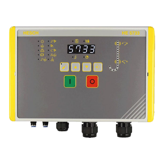
- Page 20 Device overview The HE 5733 is currently available in different versions: with measuring range 0…50 mbar (#573311002D50) with measuring range 0…100 mbar (#573311002D60) Please see nameplate for correct measuring range of your device. HE 5733 shaker filter controller Position name plate Front view HE 5733 shaker filter controller...
- Page 21 The I/O unit has two slots. The left slot is for the differential pressure module. The differential pressure module offers the following functions: EEPROM Differential pressure measurement Analogue output (with current and voltage output) Next to the differential pressure module is another slot for the thermistor module. The thermistor module is used for the temperature monitoring of the fan motor and works with PTC sensors according to DIN VDE V 0898-1-401 .
- Page 22 Reading the current resistance value You can read the current resistance value (in Ohm Ω) in the test & service menu as follows: Press the PARA key. The LED on the PARA key lights up yellow The display shows The LED test mode flashes yellow.
- Page 23 HE 5733 during thermistor monitoring If the sensor resistance increases during operation between 2650 and 4000 Ω, the fan motor might overheat and the thermistor monitoring is released. This is indicated by: LED for motor protection switch flashes red ...
- Page 24 Electrical Commissioning Before switching on the device, observe the following points: Danger of Electrocution! Electrical installation must only be carried out when the power is disconnected. Explosion Prevention! With closed cover, the device is suitable for use in explosion zone 22. Before opening the device, it is essential to ensure that no explosive environmental conditions, such as dust generation, exist.
- Page 25 Wiring diagram You can find the wiring diagram for your device under the following link: https://www.hesch-automation.com/wp-content/uploads/HE-5733-wiring-diagram.pdf Furthermore, the wiring diagram can be found in the download centre of our website: https://www.hesch-automation.com/en/support/download-center/ In tab EPLAN under section EPLAN Wiring diagrams, you can find the right diagram for your device.
- Page 26 Open the housing as described in chapter 4.3 Opening the device. a) Apply the supply voltage 400 VAC. b) Connect the PE conductors. The 7-segment display shows HE 5733 as scrolling text and the device carries out an LED test. Each LED lights up shortly once.
- Page 27 Outputs 6.4.1 Digital outputs The device has two 24 V DC digital outputs for controlling the fan contactor and the shaker contactor. The outputs are protected together by a 200 mA self-resetting fuse. 6.4.2 Relay outputs The device has two potential-free changeover contacts.
- Page 28 Assembly of measuring hose onto pressure connection 1. Push 2. Pull hose Assembly of hose onto push-in bulkhead fitting Hose connection Insert hose with 6 mm outer diameter into the connection. Hose disconnection 1. Press the blue retaining ring to open the lock. 2.
- Page 29 Display and Operating Elements Keys and LED Display and Operating Elements external Symbols/Displays Meaning External Operation signal Cleaning active Alarms active Automatic cleaning active Pre-warning time automatic cleaning Fan start-up time HE 5733 Operating Instructions #373501 | Version 1.1...
- Page 30 Symbols/Displays Meaning External Fan overrun time Fan run-down time Duration of cleaning Settling time of dust Error motor protection switch / contactor / thermistor module Test mode Differential pressure is displayed Display for setting the time-dependent parameters PARA key Parametrisation mode ON/OFF UP key ...
- Page 31 Display and Operating Elements Internal HE 5733 Operating Instructions #373501 | Version 1.1...
- Page 32 Symbols/Indicators Meaning Internal LED on dp-module Lights up, when dp-module is active LED on thermistor module Lights up, when thermistor module is active LED RUN Lights up permanently, when a supply voltage is applied LED STATUS STATUS ...
- Page 33 Differential pressure column Delta-p measuring range dp-High Alarm dp-Low Alarm Zeroing Differential pressure column During normal operation, the LEDs indicate the differential pressure. During parametrisation mode, the selected parameter value is indicated by the corresponding LED. HE 5733 Operating Instructions #373501 | Version 1.1...
- Page 34 Operation Note! The LED or LED combinations belonging to the parameters mentioned in this chapter, are listed in chapter 9.2 Overview of parameters and their LEDs. Note! For parameter setting, please refer to chapter 9.3 Parametrisation with device keys. Note! If you use one single switch for the external start/stop function, then /stop please refer to chapter 8.9 HE 5733 with static switch for start...
- Page 35 Cleaning with differential pressure monitoring If the set maximum differential pressure dp-max. is exceeded, the relay dp-alert switches. The device signalises that cleaning is necessary. For the cleaning process, switch off the fan. Press the OFF key. The fan switches off, as soon as the ‘fan overrun time’ has run out.
- Page 36 8.4.2 With dp-module (parameter setting Yes): If you have activated the parameter ‘automatic cleaning’ (Yes), the relay dp-alert switches, when reaching the maximum differential pressure ‘dp-max.’. The device signalises that an automatic cleaning starts soon (‘Pre-warning time automatic cleaning’). After ‘Pre-warning time automatic cleaning’...
- Page 37 Test & Service Press the PARA key. The LED on the PARA key lights up yellow The display shows The LED test mode flashes yellow. Press the ENTER key to open the menu Test & Service. The display shows Status display of the 5 digital inputs (Cover switch/Enable, ext.
- Page 38 Output test: shaker contactor = off Indication of current resistance value of thermistor Press the ENTER key to confirm the selected test function. The LED test mode flashes yellow The right decimal point of the display is flashing. Press the PARA key to save the entry.
- Page 39 HE 5733 with static switch for start/stop Note! When using a static switch, please keep in mind that the parameter ‘external start / stop’ must be set to static, see chapter 9.4 Parametrisation via EasyTool Controls 4.0. Note! The position of the static switch always has priority over the key operation on the device front.
- Page 40 Parametrisation Parameter Table The following parameters can be set either via the device keys as well as via EasyTool Controls 4.0: Parameter Adjustment range Step values Default setting Unit System start Cleaning Off/On (0/1) Cleaning On (1) When set to On (1), the system starts the cleaning process right after a supply voltage...
- Page 41 The following parameters can be set via EasyTool Controls 4.0 only: Parameter Adjustment range Default setting 0…9999 Password 0001 Protection against unauthorised parameter changes. External start/stop dynamic, static dynamic In case of two digital inputs and two external push-buttons for start/stop: Setting ‘dynamic’...
- Page 42 Overview of parameters and their LEDs When setting the system parameters, there are these combinations of lit or flashing LEDs: Parameter name LED flashes LED is lit System start Automatic cleaning Pre-warning time automatic cleaning Duration of cleaning Cleaning interval* Start-up time of fan Overrun time of fan Run-down time of fan...
- Page 43 Parametrisation with device keys Note! All parameters can be set via the device keys as well as via EasyTool Controls 4.0. The password and the parameter ‘external start/stop’ can only be set via EasyTool Controls 4.0 though. Press the PARA key to change the values of the system parameters.
- Page 44 Press the ENTER key to save the parameter value. The entered value is accepted. Press the PARA key to discard the parameter value. The set value is discarded. The parametrisation mode is terminated and you leave the parameter menu. ...
- Page 45 Parametrisation via EasyTool Controls 4.0 Note! All parameters can be set via the device keys as well as via EasyTool Controls 4.0. The password and the parameter ‘external start/stop’ can only be set via EasyTool Controls 4.0 though. The parameters can also be set via EasyTool Controls 4.0. Underneath the tab Parameters, you find a list of the device parameters.
- Page 46 Offset for zeroing Should a zeroing need to be carried out, a warm-up time of 30 minutes must be observed. Press the PARA key to change the values of the system parameters. The LED on the PARA key lights up yellow ...
- Page 47 Reset of default settings Switch on the device and keep the keys PARA and ENTER pressed simultaneously for 5 seconds. is shown in the display. After 5 seconds is shown in the display for entering the password. Continue with step 2. If no password has been assigned, the controller starts automatically after 5 seconds with default settings (see 9.1 Parameter Table).
- Page 48 Differential pressure measurement Connections for the differential pressure measurement The differential pressure is measured internally and passed on as a 4…20 mA / 0…10 V signal to the higher-level control system or to a display device. The current output is scalable via the adjustable measuring range.
- Page 49 EEPROM parameter error The differential pressure display shows flashing: and check parametrisation. If this does not succeed, send the device to AXXERON HESCH electronics GmbH for repair. Check the differential The differential pressure The differential pressure signal display shows: is below the permissible pressure signal.
- Page 50 If the Status LED still does not fit firmly on the PCB. does not light up, please contact the service of AXXERON and the LEDs for High HESCH electronics and Low alarm are GmbH (see chapter...
- Page 51 Display / LED Cause Remedy Error of cover switch LED for operation signal is Close the cover flashing and the 4 LEDs on the OFF key are flashing counter- clockwise: Error of rotating field The 4 LEDs on the OFF Apply the correct key are flashing counter- rotating field...
- Page 52 The device must be cleaned regularly to avoid an increased formation of dust on the device. Disposal Dispatch metals and plastics for recycling. Electrical and electronic components must be collected separately and disposed of properly. Dispose of equipped circuit boards properly. AXXERON HESCH electronics GmbH Boschstraße 8 31535 NEUSTADT, GERMANY Phone: +49 5032 9535-0 Web: www.hesch-automation.com...
Need help?
Do you have a question about the HESCH HE 5733 and is the answer not in the manual?
Questions and answers