Table of Contents
Advertisement
Quick Links
Advertisement
Table of Contents

Related Manuals for Axxeron HESCH HE 5721


Summary of Contents for Axxeron HESCH HE 5721
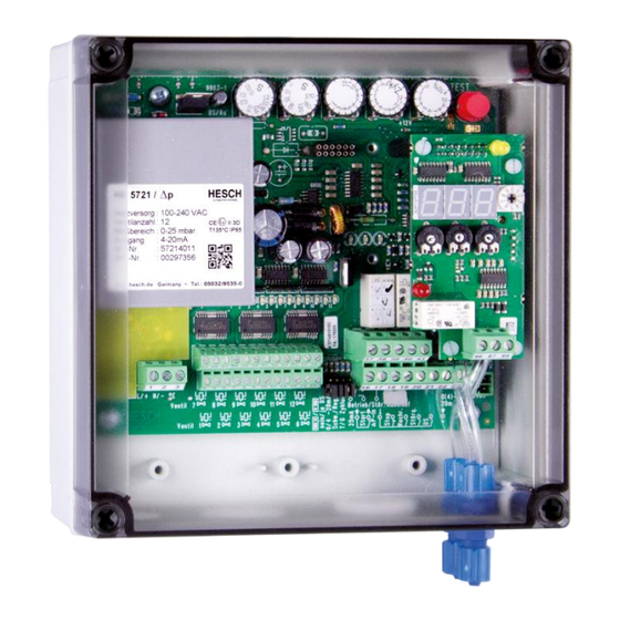
- Page 1 HE 5721 Δp-solenoid valve controller Operating Instructions (English)
- Page 2 Published by: AXXERON HESCH electronics GmbH, Documentation Department Property rights © Copyright 2023 AXXERON HESCH electronics GmbH. All rights reserved. Content, pictures and design of this manual are protected by copyright and other laws protecting intellectual property. Dissemination or alteration of the content of this manual is not permitted. Furthermore, the content may not be copied for commercial use or distribution.
-
Page 3: Table Of Contents
Table of content Versions ........................... 4 1. General Safety Instructions ..................5 1.1. Device Safety ...................... 5 1.2. Mounting ......................6 1.3. Electrical Connections ..................7 1.4. Explosion Protection (for ATEX-approved devices only!) ........9 2. General Description ....................11 Options ...................... -
Page 4: Versions
Versions Versions Date / Version Description 17.06.2014 / 2.0 Layout modifications, frontpage: Image updated. Added Documenthistory. Chapter 2.2 and 7 (Technical Data): Power supply changed to 100 – 240 VAC (wide range power supply). Chapter 1 and 7 (Technical Data): Updated device disignation; max. -
Page 5: General Safety Instructions
General Safety Instructions 1. General Safety Instructions 1.1. Device Safety This device was built and tested according to production-specifications and was shipped in safe condition. The protection class mentioned in the operating instructions is applicable. In order to maintain this condition and to ensure a safe operation, the applicant must follow the hints and warnings given in these safety notes. -
Page 6: Mounting
General Safety Instructions 1.2. Mounting In order to have a proper function each instrument has to be placed in dust-free and dry rooms, either in a panel or in the relevant socket of a 19-inch instrument carrier. The ambient temperature at the place of installation should not exceed the permissible nominal operational temperature specified in the data sheet. -
Page 7: Electrical Connections
General Safety Instructions 1.3. Electrical Connections Danger due to electrocution! All electrical wiring must be conform to local Electrical Standards (e.g. VDE 0100 in Germany). The input leads must be kept separate from signal and mains leads. The protective earth must be connected to the relevant terminal (in the instrument carrier). -
Page 8: Explosion Protection (For Atex-Approved Devices Only!)
General Safety Instructions Shut-Down For permanent shut-down, disconnect the instrument from all voltage sources and protect it against accidental operation. Before instrument switch-off, check that other equipment and / or facilities connected in the same signal loop is / are not affected. If necessary, appropriate measures must be taken. Maintenance, Repair and Modification The instrument needs no particular maintenance. - Page 9 General Safety Instructions 1.4. Explosion Protection (for ATEX-approved devices only!) Explosion protection! With the lid closed, the device is suitable for use in EX zone 22. Before opening the device, e.g. for parametrization, make absolutely sure that explosive atmospheres have been evacuated. The device is approved for the operation in explosion zone 22.
- Page 10 General Safety Instructions Use appropriate cable glands for the installation of cables and mount them professional. Don`t damage the protection class. Not used holes in the housing have to be closed dust tight with appropriate sealing screws. Operation with opened cover is not admissible.
-
Page 11: General Description
General Description 2. General Description 2.1 General The HE 5721 solenoid valve control system is used for pulse activation of solenoid valves in air pollution control systems. The HE 5721 permits numerous controlling and monitoring functions and can be extended by a differential pressure measuring and control system. -
Page 12: Installation And Housing
Installation and housing Installation and housing The instrument should be installed in such a way that it is not exposed to moisture/humidity and dirt. It must also be ensured that the permissible maximum ambient temperature (50° C) is not exceeded. The device has to be protected against direct solar radiation. Electrical connections should be made in accordance with the relevant VDE (Verein Deutscher Elektrotechniker = Association of German Electrical Engineers) regulations and/or locally applicable regulations. -
Page 13: Solenoid Valve Controller
Solenoid valve controller Solenoid valve controller Operating and display elements Potentiometer: The time setting potentiometers have a logarithmical scale division. Pulse time: 0.02 ... 1.2 s Pause time: 1... 270 s Number of valves: 1...12 valves, 12 + 1...12 valves if the valve extension board is used. See the adjusting aids for integer parameters. -
Page 14: Inputs
Solenoid valve controller Function Jumper XS1 Terminal* Note Cleaning mode ∆p-Threshold control Schw. Characteristic selection Pause time control Reg. with pause potentimeter External-∆p-signal Reg. 17,18 external signal only pause time control Timer mode Schw. 16, 17 connected Pulse- and pause poti * Terminals 18, 19 connected = release •... -
Page 15: Functions
Solenoid valve controller Functions 4.4.1 Release/Stop The input releases activation of the valves. If the contact is open, cleaning is stopped immediately. 4.4.2 Start / ∆p-IN The control system can operate in 2 operating modes. They are selected with the jumper 'XS1 Type of cleaning'. -
Page 16: Pause Control
Solenoid valve controller 4.4.5 Pressure Switch The input 'pressure switch' serves for the mechanical check the valve function. The contact must be closed before activating a valve (message: pressure exists). During the pause time, the contact has to open (message: pressure drop = valve is open) and close again (pressure rise = valve is closed). - Page 17 Solenoid valve controller Controller Characteristics 270 s 240 s 220 s 200 s 180 s 160 s 140 s 120 s 105 s 90 s 80 s 70 s 60 s 50 s 40 s 30 s 25 s 20 s 16 s 13 s 10 s...
-
Page 18: P-Extension (Option)
∆p-Extension (Option) ∆p-Extension (Option) Operating and Display Elements ● LED-displays: 3-digit seven-segment display for current differential pressure or switching thresholds 1 LED for P-Alarm (red), 1 LED for cleaning (yellow) ● Display selection: Rotary switch p-actual value [mbar] = Cleaning Stop (Lower threshold) [mbar] = Cleaning Start (Upper threshold) -
Page 19: Outputs
∆p-Extension (Option) Outputs Relay: Contact rating: 250 V AC / 5 A 1 Change-over-contact for P-alarm Terminal 66 = NC- contact Terminal 67 = NO- contact Terminal 68 = Change-over-contact ∆p-Adjustment In case of a zero drift, the display can be set to zero with the 0-point potentiometer (below the board). -
Page 20: System Parameters
System Parameters System Parameters Adjustment of System Parameters Attention! Adjustments are made during operation. If the thresholds for 'Cleaning Start' are set under the actual differential pressure, the cleaning beginns. Remedial action: increase thresholds, disconnect device briefly from power Note! Do not adjust the potentiometer without switching the display selector to that value! Cleaning Stop lower threshold... -
Page 21: Adjusting Aids For Integer Parameters
System Parameters Adjusting aids for Integer Parameters With the potentiometers also integer values are set. To support this procedure the instrument offers two adjusting aids, which both work at the same time: Display: - 1 1 1 - 2 2 - 3 3 3 - 4 4 etc. -
Page 22: Connecting Diagramm
Connecting Diagramm Connecting Diagramm 100 – 240 VAC # 371340 Solenoid valve controller HE 5721... -
Page 23: Technical Data
Technical Data Technical Data Valve Controller ● Start- / p-input 0(4)-20 mA ● Release (contact closed) / stop (contact open) ● Post-cleaning (impulse signal) ● Malfunction acknowledgement (impulse signal) ● Pressure switch for mechanical valve function monitoring Valve outputs: Max. 12, with extension 24 (option) Valve voltage: 24 VDC ±... - Page 24 p-Controller (Option) Display: 3-digit 7-segment display ● 1 LED "{P-alarm" (red) ● 1 LED "cleaning" (yellow) Measuring range: Between 0…25 and 0…500 mbar p-sensor: Max. static pressure: 1000 mbar Linearity: ±1% Hysteresis: ±0.1% Temperature hysteresis: ±0.5% Temperature drift / Zero: ±0.025% / K Temperature drift / terminal value: ±0.01% / K Analog output 0(4)…20 mA...
Need help?
Do you have a question about the HESCH HE 5721 and is the answer not in the manual?
Questions and answers