Advertisement
Quick Links
Advertisement

Subscribe to Our Youtube Channel
Related Manuals for aci KW320B Series


Summary of Contents for aci KW320B Series
- Page 1 KW320B Series BACnet IP Meter User's Manual...
- Page 2 Copyright © 2020 V2.00 This manual may not be altered or reproduced in whole or in part by any means without the expressed written consent of Automation Components, Inc.
- Page 3 ACI shall not be responsible or liable for any damages or injuries caused by improper meter installation and/or operation.
- Page 4 Chapter 1: BACnet Overview ................... 3 Chapter 2: Introduction ...................... 3 Chapter 3 About BACnet Protocol ................. 3 Chapter 4: Using the KW320B Series Power Meter's BACnet Protocol ..4 Chapter 5: Using The BACnet Module (AXM-BACnet) ........... 4 5.1 Definition of RJ45 Interface ........................4 5.2 Initializing The BACnet Module ........................5...
- Page 5 The BACnet IP protocol supports 106 objects which lets you track up 78 measurements and 28 IO parameters. The KW320B Series Power Meter supports native BACnet/IP that lets it act as a BACnet server in any BACnet application. The KW320B Series Power Meter’s BACnet IP also comes with a Web interface that allows users to configure the BACnet related parameters and read measurements by using a standard browser.
- Page 6 4. Using the KW320B Series Power Meter's BACnet Protocol There are different serial and Ethernet based-versions of BACnet. The most common serial version is called BACnet MS/TP while the dominant Ethernet version is BACnet/IP. The ACI KW320B series power meter is Ethernet BACnet/IP Only.
- Page 7 Script Content Trancieved Data+ Trancieved Data- Recieved Data+ Not Connected Not Connected Recieved Data- Not Connected Not Connected 5.2 Initializing The BACnet Modules 5.2.1 BACnet/IP Module (AXM-BIP) AXM-BIP Module's default settings are as follows: IP Address (192.168.1.254);Subnet Mask (255.255.255.0);Gateway (192.168.1.1); DNS1 (8.8.8.8);...
- Page 8 KW320B Power Meter Figure 5-3 Figure 5-4 • Once in the system settings menu, the initial page is S01 ADDR, the meters address page. Press the "P" key to go to the S03 BPS2 page. The baud rate should be at 38400. •...
- Page 9 • Press the "P” key or “E” key to change the setting to "Other" and press the "V/ A" key to confirm the setting. • Press the "H" key to back out of the system settings and press the "E" key to move the cursor to "NET"...
- Page 10 6. BACnet Objects 6.1 AXM-BIP Reading Objects The AXM-BIP module for the KW320B series power meter supports 78 predefined objects based on the meters real-time measurement parameters. There is no programming or mapping necessary to use the BACnet objects. The object's name easily identifies the measurement they contain.
- Page 11 Instance Object Type Name Object Data Type Units Analog Input Frequency Float Analog Input Phase A Voltage Float Analog Input Phase B Voltage Float Analog Input Phase C Voltage Float Analog Input Average Line Voltage Float Analog Input Line Voltage AB Float Analog Input Line Voltage BC...
- Page 12 KW320B Power Meter Instance Object Type Name Object Data Type Units Analog Input Export Reactive Energy Float Analog Input Energy Total Float Analog Input Energy Net Float Analog Input Reactive Energy Total Float kvarh Analog Input Reactive Energy Net Float kvarh Analog Input Apparent Energy...
- Page 13 Instance Object Type Name Object Data Type Binary Input IO11-DI1 Binary Input IO11-DI2 Binary Input IO11-DI3 Binary Input IO11-DI4 Binary Input IO11-DI5 Binary Input IO11-DI6 Binary Input IO11-DI1 Binary Input IO11-DI12 Binary Input IO11-DI13 Binary Input IO11-DI14 Binary Input IO11-DI1 Binary Input IO11-DI2 Binary Input...
- Page 14 KW320B Power Meter Instance Object Type Name Object Data Type Units 1001 Analog Input IO21-AI1 Float mA/Volts 1002 Analog Input IO21-AI2 Float mA/Volts 1003 Analog Input IO21-AI3 Float mA/Volts 1004 Analog Input IO21-AI4 Float mA/Volts 1005 Analog Input IO21-AI1 Float mA/Volts 1006 Analog Input...
- Page 15 7. AXM-BIP Through The Web Server 7.1 Configuring The BACnet-IP Settings To configure the BACnet related setting on the AXM-BIP, users must use the built in web server. Ensure the network settings related to the AXM-BIP is configured correctly so it can be accessed by a computer within the Local Area Network.
- Page 16 KW320B Power Meter • Select the 'BACnet-IP' tab to configure the settings related to BACnet-IP protocol. • Under "BACnet Enabled" select 'Yes' to enable the BACnet protocol. • Enter the "BACnet Port" or the UDP port number. Default port is 47808. •...
- Page 17 • Enter a "Device Name" for the device to distinguish it from other devices within the network. Under the "Enable Foreign Device Function", select 'Enable' to communicate with a BACnet device from another subnet. • Enter the IP of the BACnet Broadcast Management Device(BBMD) under the 'BBMD IP' field for the device which will receive broadcast messages on one subnet and forward them to another subnet.
- Page 18 KW320B Power Meter 7.2 BACnet Protocol Implementation Conformity Statement The PICS document for the AXM-BIP can be downloaded from the following URL: https://accuenergy.com/files/acuvim-ii/EPICS_accu.tpi.zip V: 2.0 Revised: Agust 2023 www.workaci.com...
- Page 19 KW320 Series Power Meter Chapter 8: Installation 8.1 Appearance and Dimensions 8.2 Installation Methods 8.3 Wiring V: 2.0 Revised: Agust 2023 www.workaci.com...
- Page 20 When removing meter for service, use fuses for voltage leads and power supply to prevent hazardous voltage conditions or damage to CTs. ACI recommends using a dry cloth to wipe the meter. NOTE: IF THE EQUIPMENT IS USED IN A MANNER NOT SPECIFIED BY THE MANUFACTURER, THE PROTECTION PROVIDED BY THE EQUIPMENT MAY BE IMPAIRED.
- Page 21 8.1 Appearance and Dimensions KW320 Dimensions Multifunction Power Meter 96.00 (3.800) Front View Gasket 85.4 4 85.4 (3.36) 3.36 3.36 96.00 (3.800) Side View (Display Meter) Rear View Rear View (Remote Display) Installation Clip Fig 2-1 Appearance and dimensions of KW320 series meter. V: 2.0 Revised: Agust 2023 www.workaci.com...
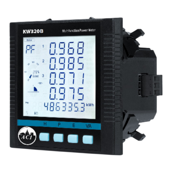
- Page 22 KW320B Power Meter Part Name Description 1. LCD Display Large bright white backlight LCD display 2. Front Casing Visible portion (for display and control) after mounting onto a panel 3. Key Four keys are used to select display and set 4.
- Page 23 Figure 2-2 Panel Cutout 2. Remove the clips from the meter and insert the meter into the square hole from the front side. Please note: optional rubber gasket must be installed on the meter before inserting the meter into the cut out. Figure 2-3 Put the meter into the opening 3.
- Page 24 KW320B Power Meter Fig 2-4 Use the clips to fix the meter on the panel Note: The display meter and the remote display unit have the same installation method. The DIN rail meter is simply installed on a 35mm DIN rail. 8.3 Wiring 8.3.1 Terminal Strips There are four terminal strips at the back of the KW320 series meter.
- Page 25 Safety Earth Connection Before setting up the meter's wiring, please make sure that the switch gear has an earth ground terminal. Connect both the meter's and the switch gear's DANGER ground terminal together. The following ground terminal symbol is used in this user's manual Only the qualified personnel does do the wire connection work.
- Page 26 KW320B Power Meter A fuse (typical 1A/250VAC) should be used in the auxiliary power supply loop. No. 13 terminal must be connected to the ground terminal of the switchgear. An isolated transformer or EMC filter should be used in the control power supply loop if there is a power quality problem in the power supply.
- Page 27 Note: The secondary side of the CT should not be open circuit in any circumstance when the power is on. There should not be any fuse or switch in the CT loop. When using mV and RCT CT's the secondary leads must not be grounded VN Connection: VN is the reference point of the KW320 series meter voltage input.
- Page 28 KW320B Power Meter KW320 Figure 2-9a 3LN Direct Connection KW320 Figure 2-9b 3LN With 3PT 3-Phase 3-Line Direct Connection Mode (3LL): V: 2.0 Revised: Agust 2023 www.workaci.com...
- Page 29 In a 3-Phase 3-Line system, power line A, B and C are connected to V1, V2 and V3 directly. VN is floated. The voltage input mode of the meter should be set to 3LL. KW320 Figure 2-10 3LL 3-Phase 3-Line Direct Connection 3-Phase 3-Line Open Delta Mode (2LL): Open Delta Wiring Mode is often used in high voltage systems.
- Page 30 KW320B Power Meter 3CT: KW320 Figure 2-12 3CT's 2CT: KW320 Figure 2-13 2CT's 1CT: KW320 Figure 2-14 1CT V: 2.0 Revised: Agust 2023 www.workaci.com...
- Page 31 8.3.5 Frequently Used Wiring Method In this section, the most common voltage and current wiring combinations are shown in different diagrams. In order to display measurement readings correctly, please select the appropriate wiring diagram according to your setup and application. KW320 Fig 2-15 3LN, 3CT LINE...
- Page 32 KW320B Power Meter LINE 1A FUSE Terminal Block KW320 LOAD Fig 2-17 1LN, 1CT LINE A N B 1A FUSE V3 V2 V1 KW320 LOAD Fig 2-18 1LL, 2CT V: 2.0 Revised: Agust 2023 www.workaci.com...
- Page 33 Phone: 1-888-967-5224 AUTOMATION COMPONENTS, INC. 2305 N Pleasant View Rd, Middleton, WI Email: techsupport@workaci.com 53562...
Need help?
Do you have a question about the KW320B Series and is the answer not in the manual?
Questions and answers