Table of Contents
Advertisement
Quick Links
Advertisement
Table of Contents

Related Manuals for aci KW320 Series


Summary of Contents for aci KW320 Series
- Page 1 KW320 Series Power Meter User's Manual...
- Page 2 Copyright © 2020 V2.00 This manual may not be altered or reproduced in whole or in part by any means without the expressed written consent of Automation Components, Inc.
- Page 3 ACI shall not be responsible or liable for any damages or injuries caused by improper meter installation and/or operation.
-
Page 4: Table Of Contents
Table of Contents Chapter 1: Introduction ................9 1.1 Meter Overview .........................10 1.2 Areas of Application ......................11 1.3 Product Features ......................11 Chapter 2: Installation ................15 2.1 Appearance and Dimensions ...................17 2.2 Installation Methods ......................18 2.3 Wiring ..........................20 2.3.1 Terminals ......................20 2.3.2 Power Requirement ..................... - Page 5 Chapter 5: Extended Modules..............82 5.1 Ethernet Module (AXM-WEB2 Included with KW320 Meter) ..........83 5.1.1 Introduciton to Ethernet ..................83 5.1.1.1 Introduction to Ethernet ................83 5.1.1.2 IPv6........................83 5.1.2 Functional Description of the Ethernet Module ..........83 5.1.3 Appearance and Dimensions ................85 5.1.4 Installation Method ....................85 5.1.4.1 Definition of RJ45 ..................86 5.1.5 Initializing the Ethernet Module ................86 5.1.5.1 Cable ......................96...
- Page 6 5.1.7.4.1.3 Data Preview ................120 5.1.7.4.2 Trendlog Management ..............121 5.1.7.4.2.1 Clear Logs ................122 5.1.7.4.3 Data Log ....................123 5.1.7.4.3.1 Deleting Data Logs ..............123 5.1.7.4.4 Alarm Log ..................124 5.1.7.4.5 SOE Log .....................125 5.1.7.4.6 Waveform Log ...................126 5.1.7.4.6.1 COMTRADE ................128 5.1.7.4.7 Event Log ..................129 5.1.7.5 About......................129 5.1.7.6 Settings .......................130 5.1.7.6.1 Meter....................130...
- Page 7 5.1.8.13 IEC61850 ....................175 5.1.8.14 Ethernet/IP ....................176 5..8.15 MQTT ......................177 5.1.8.15.1 MQTT General Settings ............177 5.1.8.15.2 MQTT Authentication ..............178 5.1.8.15.3 MQTT Encryption ..............179 5.1.8.15.4 Last Will & Testament ..............179 5.1.8.15.5 Top and Parameter Selection ..........180 5.1.8.16 Remote Access ..................181 5.1.8.17 Config Managament ................183 5.1.8.17.1 Backup Configuration .............184 5.1.8.17.2 Export/Apply Configuration ............185 5.1.8.17.3 Import Configuration ..............186...
- Page 8 Chapter 6: Communication ..............207 6.1 Modbus Protocol Introduction ..................208 6.2 Communication Format ....................210 6.3 Data Address Table and Applicaiton Details..............213 6.3.1 System Parameter Setting ..................216 6.3.2 System Status Parameters ..................218 6.3.3 Date and Time Table ...................219 6.3.4 Over/Under Limit Alarming Setting ..............220 6.3.5 I/O Modules Settings ...................222 6.3.6 100ms Refresh Metering Parameter ..............227 6.3.7 Metering Parameter Address Table ..............228...
- Page 9 V: 1.0 Revised: May 2021 www.workaci.com...
- Page 10 (RTU) that contributes to your system's stability and reliability by providing real-time power quality monitoring and analysis. When you open the package, you will find the following items: KW320 Series Meter (1) AXM-WEB2 Ethernet Module (1) Terminal Blocks (3)
-
Page 11: Chapter 1: Introduction
KW320 Series Power Meter Chapter 1: Introduction 1.1 Meter Overview 1.2 Areas of Application 1.3 Functionality... -
Page 12: Meter Overview
Ethernet ports, with multiple communication protocols available. Energy Management: The KW320 series meter is able to measure bidirectional, four quadrants kWh and kvarh. It provides maximum/minimum records for power usage and power demand parameters. All power and energy parameters can be viewed remotely via software in order to easily monitor various parameters. -
Page 13: Areas Of Application
This meter can be installed into a standard ANSI C39.1 (4" Round) or and IEC 92mm DIN (Square) cut out. With the 51mm depth after mounting, the KW320 series can be installed in a small cabinet. Mounting clips are used for easy installation and removal. - Page 14 Power Meter High Safety, High Reliability: KW320 series meter was designed according to industrial standards. It can run reliably under high power disturbance conditions. This meter has been fully tested for EMC and safety compliance in accordance with UL and IEC standards.
- Page 15 Chapter 1: Introduction Category Item Parameters KW320 KW320Q Monitoring Waveform Voltage and Trigger, Manual, DI • Capture if 400Hz Current Change, Sag/Dips, Swell, type, there is no Waveform Over Current this function Power Quality Voltage U_unbl • • Unbalance Factor Current I_unbl •...
- Page 16 KW320 Power Meter Category Item Parameters KW320 KW320Q Others Data Logging Data Logging 1 F, V1/2/3/lnavg, Data Logging 2 V12/23/13 lavg, I1/2/3/ Data Logging 3 n/avg, P1/2/3/sum, Q1/2/3/sum, S1/2/3/ sum, PF1/2/3, PF, U_ unbl, I_unbl, Load Type, Ep_imp, Ep_exp, Ep_ total, Ep_net, Eq_imp, Eq_exp, Eq_total, Eq_ net, Es, THD_V1/2/3/...
-
Page 17: Chapter 2: Installation
KW320 Series Power Meter Chapter 2: Installation 2.1 Appearance and Dimensions 2.2 Installation Methods 2.3 Wiring... - Page 18 When removing meter for service, use fuses for voltage leads and power supply to prevent hazardous voltage conditions or damage to CTs. ACI recommends using a dry cloth to wipe the meter. NOTE: IF THE EQUIPMENT IS USED IN A MANNER NOT SPECIFIED BY THE MANUFACTURER, THE PROTECTION PROVIDED BY THE EQUIPMENT MAY BE IMPAIRED.
-
Page 19: Appearance And Dimensions
96.00 (3.800) Front View Gasket 85.4 4 85.4 (3.36) 3.36 3.36 96.00 (3.800) Side View (Display Meter) Rear View Rear View (Remote Display) Installation Clip Fig 2-1 Appearance and dimensions of KW320 series meter. V: 1.0 Revised: May 2021 www.workaci.com... -
Page 20: Installation Methods
KW320 series meter should be installed in a dry and dust free environment. Avoid exposing the meter to excessive heat, radiation and high electrical noise sources. Installation Steps: The KW320 series meter can be installed into a standard ANSI C39.1 (4" Round) or an IEC 92mm DIN (Square) form. V: 1.0 Revised: May 2021... - Page 21 Chapter 2: Installation 1. Cut a square hole or round hole on the panel of the switch gear. The cutting size is show in fig 2-2. Figure 2-2 Panel Cutout 2. Remove the clips from the meter and insert the meter into the square hole from the front side. Please note: optional rubber gasket must be installed on the meter before inserting the meter into the cut out.
-
Page 22: Wiring
2.3 Wiring 2.3.1 Terminal Strips There are four terminal strips at the back of the KW320 series meter. The three-phase voltage and current are represented by using 1, 2 and 3 respectively. These numbers have the same meaning as A, B and C or R, S and T used in other literature. -
Page 23: Power Requirement
Figure 2-6 Safety Earth Symbol 2.3.2 Power Requirement Control Power: There are 2 options for the Control Power of the KW320 series NOTE meter: Make sure the control power Standard: 100~415 VAC (50/60Hz) or 100-300VDC... - Page 24 Choice of wire of power supply is AWG 22-16 or 0.6-1.5 mm2. Voltage Input: Maximum input voltage for the KW320 series meter shall not exceed 400LN/690LL VAC rms for three phase or 400LN VAC rms for single phase. Potential Transformer (PT) must be used for high voltage systems.
-
Page 25: Voltage Input Wiring
Chapter 2: Installation VN Connection: VN is the reference point of the KW320 series meter voltage input. Low wire resistance helps improve the measurement accuracy. Different system wiring 20 modes require different VN connection methods. Please refer to the wiring diagram section for more details. - Page 26 KW320 Power Meter KW320 Figure 2-9b 3LN With 3PT 3-Phase 3-Line Direct Connection Mode (3LL): In a 3-Phase 3-Line system, power line A, B and C are connected to V1, V2 and V3 directly. VN is floated. The voltage input mode of the meter should be set to 3LL. KW320 Figure 2-10 3LL 3-Phase 3-Line Direct Connection V: 1.0 Revised: May 2021...
-
Page 27: Current Input Wiring
Chapter 2: Installation 3-Phase 3-Line Open Delta Mode (2LL): Open Delta Wiring Mode is often used in high voltage systems. V2 and VN are connected together in this mode. The voltage input mode of the meter should be set to 2LL for this voltage input wiring mode. -
Page 28: Frequently Used Wiring Method
KW320 Power Meter 2CT: KW320 Figure 2-13 2CT's 1CT: KW320 Figure 2-14 1CT 2.3.5 Frequently Used Wiring Method In this section, the most common voltage and current wiring combinations are shown in different diagrams. In order to display measurement readings correctly, please select the appropriate wiring diagram according to your setup and application. - Page 29 Chapter 2: Installation LINE A B C 1A FUSE Terminal Block V3 V2 V1 KW320 LOAD Fig 2-16 2LL, 3CT LINE 1A FUSE Terminal Block KW320 LOAD Fig 2-17 1LN, 1CT LINE A N B 1A FUSE V3 V2 V1 KW320 LOAD Fig 2-18 1LL, 2CT...
-
Page 30: Communication
RS485 bus. Use good quality shielded twisted pair cable, AWG22 (0.5mm2) or higher. The overall length of the RS485 cable connecting all devices should not exceed 1200m (40000 ft). The KW320 series meter is used as a slave device of masters such as a PC, PLC, Data Collector or RTU. -
Page 31: Chapter 3: Meter Display And Parameter Settings
KW320 Series Power Meter Chapter 3: Meter Display and Parameter Settings 3.1 Display Panel and Keys 3.2 Metering Data 3.3 Statistics Data 3.4 Demand Data 3.5 Harmonic Data 3.6 Expanded I/O Module Data 3.7 Parameter Settings Mode 3.8 Page Recovery Function... -
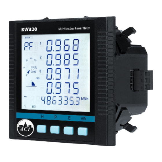
Page 32: Display Panel And Keys
3.1 Display Panel and Keys The front of the KW320 series meter consists of an LCD screen and four control keys. All the display segments are illustrated in Fig 3-1. Users should note that all the segments will not display in a single page under normal conditions. - Page 33 Chapter 3: Meter Display and Parameter Settings Display Description Display mode indication S how s d iffe re n t m o d e s o n t h e d is p l a y a rea . "Meter" for real-time measurement | "Max/Min" for statistic data | "Demand"...
-
Page 34: Metering Data
KW320 Power Meter Display Description Communication icon No icon: no communication | One icon: query sent | Two icons: query sent and response received Energy pulse output No icon: no pulse output | With icon: icon blinks indicator when sending pulse output Expanded I/O module indicator M1: one AXM-IO1 connected | M1x2: two AXM-IO1 connected Profibus module... - Page 35 Chapter 3: Meter Display and Parameter Settings The following figure shows the sequence: Three Phase Voltage & Avg Three Phase Current & In Line Voltage & Avg Three Phase Current & Avg Note: When the meter is set to "2LL" or "3LL", there is no phase voltage or neutral current display.
- Page 36 KW320 Power Meter Note: When the meter is set to "2LL" or "3LL", only the fifth screen (system power) and the sixth screen (system power factor & frequency) will be displayed. When the meter is set to "1LN", there are only phase A power and phase A power factor display. When the meter is set to "1LL". there are no phase C power and phase C power factor display.
-
Page 37: Statistics Data
KW320 series meter can be set to record primary energy or secondary energy. The unit of energy is kWh for active energy, kvarh for reactive energy and kVAh for apparent energy. The running time has a resolution of 0.01h. The meter begins accumulating time upon initial powering up of the unit. -
Page 38: Demand Data
KW320 Power Meter display is the maximum phase voltage value, when V/A is pressed, the display will show the minimum phase voltage value. If V/A is pressed again, the display will switch back to show the maximum phase voltage value. The following figure shows the sequence: Max value of phase voltage Max value of power demand... -
Page 39: Harmonic Data
Chapter 3: Meter Display and Parameter Settings 3.5 Harmonic Data Pressing H and V/A simultaneously will activate the display mode selection and the cursor will flash. Press P or E to move the cursor right or left. To enter harmonic mode, move the cursor to "Harmonic", then press V/A. -
Page 40: Parameter Setting Mode
KW320 Power Meter Note: When the meter is set to "1LN", there is only phase A display for voltage THD, voltage odd HD, voltage even HD, THFF, voltage crest factor, current THD, current odd HD, current even HD and current K factor. When the meter is set to "1LL", there is no phase C display. B) Harmonic Ratio Data: Press H to switch to power quality data display. - Page 41 Chapter 3: Meter Display and Parameter Settings A) Password Inquiry: Parameter setting mode is password protected. Before entering the password and getting into the parameter setting mode, the meter's device communication address will display for 3 seconds. A four digit password (0000 to 9999) is required every time before accessing the parameter setting mode.
- Page 42 KW320 Power Meter Press V/A to select and modify the parameter. The figure shows the parameter selection page. "SYS" stands for system parameter, "I/O" stands for expanded I/O module parameter, "NET" stands for Ethernet module parameter or BACnet module parameter ("MESH" stands for mesh module) and "ALM"...
- Page 43 Chapter 3: Meter Display and Parameter Settings The following figure shows the sequence: SYS setting MODBUS: range is 1~247 S01: first communication DNP3.0: range is 0~65534 address S02: Baud rate Select form 1200, 2400, 4800, 9600, 19200, 38400 bps "Baud rate for external RS485 module select from 4800, 9600, 19200, 38400 bps" | Ethernet module S03: Baud rate and Profibus module only selects 38400 bps | Mesh module only selects 9600 bps Voltage wiring mode can be one of "3LN", "2LL", "3LL", "1LN"...
- Page 44 KW320 Power Meter To clear the Max and Min value does not mean write 0 to all the registers, it will copy the metering S16: max/min clear value to the statistic registers and start a new statistic period. S17: run hour clear Yes: clear, No: not clear To adjust polarity of current, the three-current's direction can be set as "Negative"...
- Page 45 Chapter 3: Meter Display and Parameter Settings 0: Base, 1: full S32: type of energy 0:50HZ, 1:60HZ, 2:400HZ | When select 400H type, only support full function. S33: frequency 2: Mesh, 1: BACnet, 0:Other Protocols if using BACNet module, you should select BACNet, Mesh S34: second communication module, you should select Mesh, if you are using Ethernet, Profibus, RS485 module, should select protocol...
- Page 46 KW320 Power Meter DI of AXM-IO-1 can be used as the pulse counter, each DI function corresponds to one I/O: M11/M12 Module bit of a 6-bit register. The correspondence bit of 0 means that the DI works as the digital status input and the correspondence bit of 1 means that the DI works as the pulse counter.
- Page 47 Chapter 3: Meter Display and Parameter Settings DI of AXM-IO-1 can be used as the pulse counter, each DI function corresponds to one I/O: M21/M22 Module bit of a 6-bit register. The correspondence bit of 0 means that the DI works as the digital status input and the correspondence bit of 1 means that the DI works as the pulse counter.
- Page 48 KW320 Power Meter The following table shows the sequence: DI of AXM-IO-1 can be used as the pulse counter, each DI function corresponds to one I/O: M31/M32 Module bit of a 6-bit register. The correspondence bit of 0 means that the DI works as the digital status input and the correspondence bit of 1 means that the DI works as the pulse counter.
- Page 49 Chapter 3: Meter Display and Parameter Settings Key functions for finding the Ethernet module parameter: • Press H to return to parameter selection mode • The screen will roll to the next page each time P is pressed and will return to the first page when P is pressed at the last page •...
- Page 50 KW320 Power Meter The following figure shows the sequence of Ethernet module: Ethernet setting N01: DHCP setting The selection of DHCP setting: MANU or AUTO Default setting: MANU N02: IP address IP address has four segments. Any segment can be set from 0~255. Default setting: 192.168.1.254 Submask has four segments.
- Page 51 Chapter 3: Meter Display and Parameter Settings BACnet IP module rolling sequence: BACnet setting The selection of DHCP setting: MANU or AUTO Default setting: MANU B01: DHCP setting B02: IP address IP address has four segments. Any segment can be set from 0~255. Default setting :0.0.0.0 Submark has four segments.
- Page 52 KW320 Power Meter BACnet MS/TP module rolling sequence: BACnet MS/TP Setting Range from 0~127, the default value is 0 B01: MS/TP node add B02: MS/TP baud Baud, 0:9600; 1:19200; 2: 38400; 3:57600 B03: Max Info Frames Range from 1~255, the default value is 1 B04: BACnet resetting 0: No resetting;...
- Page 53 Chapter 3: Meter Display and Parameter Settings Key functions for modifying the parameter: • Press H to move the flashing cursor to the next position • Press P to increase the number by 1 • Press E to decrease the number by 1 •...
-
Page 54: Page Recovery Function
3.7 Page Recovery Function KW320 series meter has a page recovery function. This means that the meter stores current display page in the non-volatile memory upon power loss and reloads the page when power recovers. If power goes off when viewing under the parameter setting mode, the meter will show voltage display when power recovers. -
Page 55: Chapter 4 Detailed Functions And Software
KW320 Series Power Meter Chapter 4: Detailed Functions and Software 4.1 Basic Analog Measurements 4.2 Max/Min 4.3 Harmonics and Power Quality Analysis 4.4 Over/Under Limit Alarming 4.5 Data Logging 4.6 Power Quality Event Logging and Waveform Capture 4.7 Seal Function... -
Page 56: Basic Analog Measurements
KW320 Power Meter The KW320 series meter contains advanced metering tools and is able to measure a multitude of power, energy and power quality parameters. Some advanced functions may not be accessible directly from the meter front; therefore, every meter comes with a powerful software that helps access the information. - Page 57 Chapter 4: Functions and Software Demand: This meter consists of several types of demand calculation: total active power demand, total reactive power demand, total apparent power demand, phase A current demand, phase B current demand, and phase C current demand. When demand is reset, demand memory registers are set as 0.
- Page 58 KW320 Power Meter Fig 4-2 Energy and Power Quality Parameters Current Direction Adjustment: Under normal circumstances, current flows from input terminal 1 to terminal 2 (i.e. from I11 to I12 for phase A current); however, current may flow in the opposite direction due to incorrect wiring setup.
-
Page 59: Max/Min
Fig 4-3 Max/Min 4.2 Max/Min KW320 series meter logs maximum and minimum value statistics for phase/ line voltages, current, power, reactive power, apparent power, power factor, frequency, demand, unbalance factor, THD as well as the time they occur. All data is stored in nonvolatile memory so that statistic information can be preserved even when meter is shut off. -
Page 60: Harmonics And Power Quality Analysis
They are shown in Fig 4-4. Sequence component and unbalance analysis: KW320 series meter is able to perform sequential analysis for the input signal. It looks at the positive sequence, negative sequence and zero sequence of 73 the fundamental frequency and performs unbalance analysis for voltage and current. -
Page 61: Over/Under Limit Alarming
Chapter 4: Functions and Software 4.4 Over/Under Limit Alarming KW320 series meter has over/under limit alarming capabilites. When the monitored parameter goes over/under the preset limit and stays at the level over the preset amount of time delay, the over/under limit alarm will be triggered. The over/under limit value and its time stamp will be recorded in the 74-alarming log. - Page 62 KW320 Power Meter Single Alarming Group Setting: Table 4-1 indicates the first group of settings, there are 16 groups in total with the same format. Address Parameter Range Property 104EH First group: parameter code 0~79 104FH First group: comparison mode 1: larger | 2: equal | 3:smaller 1050H First group: setpoint value...
- Page 63 Chapter 4: Functions and Software register. The corresponding bit must be set to "1" in order to activate the alarm channel. Logic "AND" between alarm setting: The 16 alarming records in the meter are divided into 8 pairs. Each pair has two alarm groups. The two groups can be logically “AND” by controlling the logic check box.
- Page 64 “Global alarming enable (1046H)” set to 1 to enable over/under limit alarming. Records of Alarming Event: KW320 series meter has built in alarm logging capabilities. 16 entries can be recorded in total. The record sequence of these entries do not depend on the sequence of the 16 alarm channels.
- Page 65 Chapter 4: Functions and Software or not, 1 means enabled and 0 means not. Bit0 indicates whether alarming has occured or recovered, 1 means occurred and 0 means recovered. Undefined bits are 0. “Parameter code” specifies the monitored parameter. “Value” shows the recorded value of the selected parameter when an alarm is triggered and when it recovers.
-
Page 66: Data Logging
KW320 Power Meter Fig 4-7 Basic settings 4.5 Data Logging The KW320 and KW320Q meter provides data logging that records the data at a set interval. This meter has 8 GB of memory which gives it extensive datalogging capabilities. It has a real- time clock that allows logs to be time-stamped when log events are created. - Page 67 Chapter 4: Functions and Software Fig 4-8 The data log 1 setting Having three sets of historical logs provides you with the option of programming each log with unique parameters. For example, you can program Historical Log 1 to record measured values parameters (for example, Frequency, Voltage, Current), Log 2 to record energy values parameters, and Log 3 to record power quality parameters.
- Page 68 KW320 Power Meter • THD Volts CN/CA (THD, average THD, 2nd-63rd Harmonic Magnitudes, ODD, EVEN, CF and THFF of Volts CN/CA) • THD IA (THD, 2nd-63rd Harmonic Magnitudes, ODD, EVEN, KF of IA) • THD IB (THD, 2nd-63rd Harmonic Magnitudes, ODD, EVEN, KF of IB) •...
- Page 69 Chapter 4: Functions and Software Three Modes of historical log: A. Mode1: if correctly set historical log, can record without setting date and time, depending on first-in first-out recycling log. B. Mode2: if correctly set historical log, as set date and time, can record within begin to end time.
-
Page 70: Power Quality Event Logging And Waveform Capture
KW320 Power Meter The "read one window" method allows you to access and read a specific log location at an offset from the first log. The "window record num" is the maximum number of record entries the software can read at a time, it is calculated by 246 / Record Size. The larger this number is, the faster data can be retrieved. - Page 71 Chapter 4: Functions and Software Event Logging Triggering Conditions: • Voltage Sag When any phase of the three-phase voltage is lower than the set value (voltage rated value x threshold %), there will be a voltage sag event. When one phase voltage sag happens, the other phase will not respond to voltage sag event logging.
- Page 72 KW320 Power Meter Event Log Retrieve: When a new event log commences, the newest event number address (0X8CFDH) contains the newest event number. When the log is being retrieved, the starting event log number (0X8CFEH) and the event quantity for 96 each retrieve (0X8CFF) must be set correctly. It must be ensured that the starting number of event log should equal or smaller than the newest log number.
- Page 73 Chapter 4: Functions and Software Waveform Capture KW320Q can record 100 groups of voltage and current waveform data at a sampling rate of 64 points per cycle. It provides the captured waveform of 10 cycles before and after the triggering point (including U1, U2, U3, I1, I2, I3).
- Page 74 KW320 Power Meter Waveform Order: • Before triggering point 10 U1 waveforms, 10 U2 waveforms, 10 U3 waveforms, 10 I1 waveforms, 10 I2 waveforms, 10 I3 waveforms. • After triggering point 10 U1 waveforms, 10 U2 waveforms, 10 U3 waveforms, 10 I1 waveforms, 10 I2 waveforms, 10 I3 waveforms.
- Page 75 Chapter 4: Functions and Software enabled, both event logging and waveform capture will be implemented at the same time once a voltage sag happens. Voltage Swell Triggering As mentioned in Voltage Swell event logging, when Voltage Swell Triggering Waveform is enabled, both event logging and waveform capture will be implemented at the same time once a voltage swell happens.
- Page 76 KW320 Power Meter Second retrieving method is retrieving all waveforms data. When 0x8E01H (Waveform Group Number) is set to 1~121, each time only one group data of each number will be retrieved, then Waveform Group Number for Retrieving (8E01H) will automatically add 1 after retrieving. At next time, new Waveform Group Number will be retrieved.
- Page 77 Chapter 4: Functions and Software 8E00H Waveform Group Number 1~100 Retrieving Note: When the value is smaller than or equal to neweest waveform record group number, this value is valid 8E01H Waveform Group Number Waveform number 0~121 8E02H Waveform record window status 0x0BH: window data is valid 0xFF: window data is invalid 0xAA: waveform record memory is...
-
Page 78: Seal Function
KW320 Power Meter Fig 4-12 Note: When selecting 400Hz type, not support event logging and wave capture. 4.7 Sealing Function The panel with seal, which has sealed key control, is different with one without seal. When the seal is in opened status, functions are same like normal meters. But when the seal is in sealed status, some functions of meters, which include parameters blocked by seal and optional parameters, will be blocked. - Page 79 Chapter 4: Functions and Software Addresses about seal function are 101EH and 101FH. Address 101EH is about parameters blocked by seal, which can be configured by users. These setting will be valid only when seal is in sealed status. Address 101FH is about if seal function is valid. When the panel is normal one, or the seal panel is in invalid sealed status, this address will show seal is open.
- Page 80 KW320 Power Meter Note: " ✔ " means these addresses will be blocked for keys and communication, and "-" means this function is unavailable. Energy: Address Parameter Description Communication 4048H-4049H Energy IMP ✔ 404AH-404BH Energy EXP ✔ 404CH-404DH Reactive energy IMP ✔...
- Page 81 Chapter 4: Functions and Software Sealed Nonstandard Parameters When bit 0 of address 101EH is valid, parameters about 1st communication should be blocked. Address Parameter Description Communication 10A5H Working mode of DO 1 and 2 ✔ ✔ 10A6H DO pulse width ✔...
- Page 82 KW320 Power Meter Address Parameter Description Communication DNS2 3rd byte (high) ✔ ✔ DNS2 4th byte (low) ✔ ✔ Ethernet Module Modbus Tcp/Ip port ✔ ✔ Http port ✔ ✔ BACnet module enable ✔ ✔ DHCP setting ✔ ✔ IP address 1st byte (high) ✔...
- Page 83 Chapter 4: Functions and Software When bit 2 of address 101EH is valid, parameters below should be blocked. Address Parameter Description Communications 1011H Run time clear ✔ ✔ When bit 3 of address 101EH is valid, parameters below should be blocked. Address Parameter Description Communication...
-
Page 84: Chapter 5: Extended Modules
KW320 Series Power Meter Chapter 5: Extended Modules 5.1 Ethernet Module (AXM-WEB2) -
Page 85: Ethernet Module (Axm-Web2 Included With Kw320 Meter)
This module supports the Modbus-TCP protocol. When connected to the KW320 series meter, it is a slave device that can only respond to queries. The default value for the Modbus Port is 502. - Page 86 KW320 Power Meter The AXM-WEB2 protocol supports HTTPS protocol. It is used as an HTTPS server and where the default value of the protocol port is 443. Using the HTTPS protocol, the AXM-WEB2 can send post requests to both HTTP and HTTPS servers. The following are all the protocols supported by the AXM-WEB2 module: •...
-
Page 87: Appearance And Dimensions
Remove cover from the back of the KW320 series meter which will expose the socket. Insert the installation clips to the grooves in the KW320 series meter and then press the AXM-WEB2 module lightly to establish a linking between meter and module. -
Page 88: Definition Of Rj45
LED_R (Green): Displays the link and activity status. When the LED is on it indicates the link status. When the LED is flashing it indicates that there is activity. 5.1.5 Initializing the Ethernet Module The default settings in the KW320 series meter are as followed: Ethernet 1 (Static IP address) IP Address (192.168.1.254) Subnet Mask (255.255.255.0) - Page 89 WEB2 module: Press the 'H' and 'V/A' buttons simultaneously on the KW320 series. Release the buttons and the meter will enter the meter selecting mode, as indicated by the flashing 'Meter' cursor.
- Page 90 KW320 Power Meter You will be required to type in a password in the ‘PASSWORD’ screen. Leave the password as default ‘0000’ and press ‘V/A’ to enter the parameter selection Mode. The cursor will be on ‘SYS’. Press ‘V/A’ on this screen to get to the system settings. This will show screen ‘S01 ADDR’.
- Page 91 Chapter 5: Extended Modules Press the 'E' button until you get to 'S34 PROTOCOL 2'. Select the 'WEB2' protocol. • Press ‘V/A’ to modify the setting; the cursor should now flash. • Press ‘P’ or ‘E’ to select 'WEB2'. • Press ‘V/A’...
- Page 92 KW320 Power Meter The first page of the NET Settings will be the N01 DHCP setting. By default this is configured to Manual. Setting this configuration to Auto will allow the router to assign the meter with an IP address, whiles Manual will allow the user to configure the IP address. Press the 'V/A' button to enter edit mode.
- Page 93 Chapter 5: Extended Modules Press 'P' to get to "N03 Subnet Mask". Press 'V/A' to configure the subnet address. The cursor of the first digit will begin to flash. Press the 'H' button to scroll through the digits, press the 'P' or 'E' to change the value of the flashing cursor and press 'V/A' to confirm.
- Page 94 KW320 Power Meter Press 'P' to get to "N05 DNS Primary Server". Press 'V/A' to configure the DNS address. The cursor of the first digit will begin to flash. Press the 'H' button to scroll through the digits, press the 'P' or 'E' to change the value of the flashing cursor and press 'V/A' to confirm.
- Page 95 Chapter 5: Extended Modules Press 'P' to get to "N07 Modbus Port". Press 'V/A' to configure the Modbus Port. The cursor of the first digit will begin to flash. Press the 'H' button to scroll through the digits, press the 'P' or 'E' to change the value of the flashing cursor and press 'V/A' to confirm.
- Page 96 KW320 Power Meter Press 'P' to get to "N09 NET REST". After making any changes to the NET settings, users must reboot the Ethernet module from this page for the settings to take effect. Press 'V/A' to reboot the module, the cursor will begin to flash. Press the 'P' or 'E' button to change the setting to 'Reset' and press 'V/A' to confirm.
- Page 97 Chapter 5: Extended Modules Press 'P' to get to "N11 WiFi" This is the IP address of WiFi and will be the IP address to access the web interface of the module by using WiFi connection. This IP address cannot be modified from the meters display, it can only be configured on the meters web server.
-
Page 98: Cable
KW320 Power Meter 5.1.5.1 Cable An RJ45 cable is needed to connect the meter to the network. A shielded twisted pair cable(standard 568A or standard 568B) is recommended as reference to the EIA/TIA standard. 5.1.6 Connection Method 5.1.6.1 Direct Connect to a Computer The AXM-WEB2 can be connected to a computer using a crossover cable(standard 568A). - Page 99 Chapter 5: Extended Modules • Click on Change adapter options • Once there, right click on the local area connection icon and select properties. V: 1.0 Revised: May 2021 www.workaci.com...
- Page 100 KW320 Power Meter • Select the icon that says Internet Protocol Version 4 TCP/IP • The Internet Protocol Version 4(TCP/IP) Properties box will pop up V: 1.0 Revised: May 2021 www.workaci.com...
-
Page 101: Direct Connect To A Router/Switch
Chapter 5: Extended Modules • Click on ''Use the following IP address'' and enter in an IP number so that meter and computer are in the same local network range. For example, if the meter has IP address of 192.168.1.254, then the computer must be assigned with an IP 192.168.1.xxx, where xxx can be any number but cannot be the same as the value the meter has. -
Page 102: Connect Through Wifi
KW320 Power Meter 5.1.6.3 Connect through WiFi The AXM-WEB2 can be connected through WiFi network. By default the AXM-WEB2 will be in Access Point mode with default IP address of 192.168.100.1. Ensure the device connecting to the AXM-WEB2 has DHCP enabled or it should be in the same subnet as the AXM-WEB2. - Page 103 Chapter 5: Extended Modules Field Length Description Identification of a Modbus Transaction Identifier 2 Bytes Request/Response transaction Protocol Identifier 2 Bytes Modbus Protocol = 0 Length 2 Bytes Number of following bytes Unit Identifier 1 Byte Slave address, in the range of 0-247 decimal c.
-
Page 104: Format Of Communication
KW320 Power Meter 5.1.6.4.2 Format of Communication Explanation of frame Transaction Transaction Protocol Protocol Unit Length hi Length lo identifier hi identifier lo identifier hi identifier lo identifier Function Code Data start register hi Data start register lo Data # of registers hi Data # of registers lo The meaning of each abbreviated field above is: Transaction identifier hi: High byte of transaction identifier Transaction identifier lo: Low byte of transaction identifier... - Page 105 Chapter 5: Extended Modules 1) Read Status of Relay (Function code 01) Function Code 1 This function code is used to read the relay output status in the KW320 series meter. 1=On 0=Off There are 8 relay outputs in the KW320 series meter and they start at address 0000H.
- Page 106 Function Code 2 1=On 0=Off There are 28 DIs in the KW320 series meter starting at address 0000H. The following query is to read 4 DI statuses of AXM-IO1 module with logic address of 1 in the KW320 series meter.
- Page 107 3) Read Data (Function Code 03) Function Code 3 Query This function allows the user to obtain the measurement results of the KW320 series meter. Below is an example to read 6 registers corresponding to the device clock of the meter, starting at 1040H.
- Page 108 Function Code 5 Query This function code enables the control of a single relay output in the KW320 series meter. Any relay output in the KW320 series meter can be controlled on or off starting at 0000H. Sending the data 'FF00H' will set they relay output on and sending '0000H' will turn it off; all other values are illegal and will not affect they relay output status.
- Page 109 This function code allows the user to modify the contents of a register. The example below is a request to an KW320 series meter with device address 1 to preset the CT1(500) and CT2(5) registers. The CT1 data address is 1008H and CT2 is at 1009H.
-
Page 110: Web Interface Readings And Parameter Settings
KW320 Power Meter 5.1.7 Web Interface Readings and Parameter Settings The AXM-WEB2 module supports the HTTPS protocol to allow for the use of a web interface. The user will need to access the AXM-WEB2 web interface to configure the module and use its functions. -
Page 111: Dashboard
Chapter 5: Extended Modules The two different access levels are summarized below: Access Level Default Password Read Parameter/Status Configure Settings User view Admin admin 5.1.7.2 Dashboard In the dashboard, the user will find the tabs to access different pages in the web interface such as ' Metering ', ' Logs ', and ' Settings '. -
Page 112: Metering Web Page
5.1.7.3.1 Basic Metering The Basic Metering webpage includes the data of real-time parameters for the KW320 series meter. This includes the Line Voltages, Phase Voltages, Current, Neutral Current, Active, Reactive and Apparent Power, Power Factor, Frequency and Load type. -
Page 113: Power & Energy
Chapter 5: Extended Modules 5.1.7.3.2 Power & Energy The Power & Energy webpage shows the energy data for the KW320 series meter such as the Active and Reactive energy that is consumed and delivered as well as the Apparent energy per phase and total. -
Page 114: Min/Max
KW320 Power Meter 5.1.7.3.3 Min/Max The Min/Max page shows the maximum and minimum statistics that the meter has records since the life time of the meter or from the last reset of the min/max statistics as well as the timestamps they were recorded at. The parameters in this web page are updated every 10 sec. -
Page 115: Thd
Chapter 5: Extended Modules 5.1.7.3.4 THD The THD web page shows the power quality data such as the THD, THFF, Crest and K Factor for both the voltage and current. The parameters in this web page are updated every 15 sec. 5.1.7.3.5 Harmonics The Harmonics web page will show the harmonics of the voltage and the current waveform being measured. -
Page 116: Phase Angles
KW320 Power Meter 5.1.7.3.6 Phase Angles The Phase Angles web page will show the phase angles of the voltage and current waveform being measured which can be used for remote troubleshooting. This page provides a visual diagram of the phase angles with respect to the voltage connected to the Phase A voltage input. -
Page 117: Sequence
Chapter 5: Extended Modules 5.1.7.3.7 Sequence The Sequence web page will show the positive, negative and zero components of the voltage and current waveform being measured. The parameters in this web page are updated every 10 sec. V: 1.0 Revised: May 2021 www.workaci.com... -
Page 118: I/O
KW320 Power Meter 5.1.7.3.8 I/O The I/O web page displays the status of the I/O modules that are connected and their values depending on the model of the module that is connected to the meter. I.E. The AXM-IO11 module will display the Relay Output status(on/off), DI status/counter. The I/O module can be configured in the general settings section of the web interface which is discussed later in the manual. -
Page 119: Logs
There are six kinds of logs that can be viewed, they are "Trend Log", "Trendlog Management", "Data Log", "Alarm Log", "SOE Log" Event Log and "Waveform Log"(Only available in KW320W model). Each web page shows data from the KW320 series meter. V: 1.0 Revised: May 2021 www.workaci.com... -
Page 120: Trendlog
KW320 Power Meter 5.1.7.4.1 Trendlog The Trend Log web page includes the real-time and energy trend diagram. The real-time trend log diagram can be selected to show the following parameters phase voltage, line voltage, current, active power, reactive power, apparent power and power factor for each phase as well as the totals. -
Page 121: Energy
Chapter 5: Extended Modules 5.1.7.4.1.2 Energy Similarly the energy parameters can be trended at different time intervals depending on the Time Frame selected. The table below displays the time intervals: Time Frame Time Intervals Last 10 minutes 1 second 15 seconds 1 minute Last 1 hour 1 minute... -
Page 122: Data Preview
KW320 Power Meter 5.1.7.4.1.3 Data Preview The data preview allows the user to view the graphical data in tabular form. User can also download this data into a csv file for further examination. V: 1.0 Revised: May 2021 www.workaci.com... -
Page 123: Trendlog Management
Chapter 5: Extended Modules 5.1.7.4.2 Trendlog Management The trendlog management page allows the user to download data from the meters data base. The trendlog management page acts as a back up to the data logs for users. Log Param Type: Users can select which data they want to download from the meter. In the drop down menu there is a timestamp range to show the available data. -
Page 124: Clear Logs
KW320 Power Meter 5.1.7.4.2.1 Clear Logs The clear logs function allows the user to clear and remove all metering data stored on the module database. This will allow users to clear all readings and historical data without resetting all features and functions. Users can clear the logs by clicking on the button at the bottom of the Trendlog page. -
Page 125: Data Log
Chapter 5: Extended Modules 5.1.7.4.3 Data Log The data log web page includes all the data file for three different loggers and AcuCloud. You can select the different loggers by clicking the logger tab. After the logger is selected, the log file for this logger will show on the screen with the update time and file size. -
Page 126: Alarm Log
KW320 Power Meter 5.1.7.4.4 Alarm Log The Alarm Log web page provides the user with a summary of the alarm events that have occurred with the meter. It will show the status of up to 16 alarm events indicating the alarm ID, status, parameter, value that exceeded or went below the threshold and the timestamp of the alarm event. -
Page 127: Soe Log
The SOE web page will display the Sequence of Event log for the enabled I/O module that is attached to the KW320 series meter with timestamps and will display the DI status for up to 20 SOE events. The SOE must be enabled from the Acuview software. -
Page 128: Waveform Log
Power Meter 5.1.7.4.6 Waveform Log The waveform log is available only on KW320Q models of the KW320 series meter. This meter supports a waveform capture function that allows users to capture and record 10 cycles before and after the triggering point whether it be a voltage sag, swell, or over current. The waveform log on the web interface allows users to view these waveforms whenever a power quality event has occurred. - Page 129 Chapter 5: Extended Modules Users can select 'Close' to close the waveform and navigate back to the waveform Log. Users can perform a manual waveform capture by clicking on 'Manual Capture'. This will manually capture voltage and current waveforms of the system being monitored. Once the waveform is capture it will take approximately 1-2 minutes to appear in the waveform log.
-
Page 130: Comtrade
KW320 Power Meter In the waveform log page, user also have the option to select and delete waveform files. Simply click on the check box next to the file to select it, alternatively users can click on the 'Select All' button. -
Page 131: Event Log
The About tab located at the top right corner of the web interface allows users to view the Device Information page. This page provides users with information about the KW320 series meter and the AXM-WEB2 module. The Device Information contains the model of the KW320 meter, serial number, firmware version and the meter addresses. -
Page 132: Settings
KW320 Power Meter 5.1.7.6 Settings 5.2.7.6.1 Meter 5.1.7.6.1.1 General Setting The basic metering configurations needed to set up the meter can be applied from the web interface by clicking on Settings and selecting the 'Meter' tab. On the metering tab users will see the 'General' tab selected and the page presented. - Page 133 Chapter 5: Extended Modules The general page include the following settings: Device Description: A description for the meter can be provided in this field which will display on the Dashboard page. Voltage Wiring: Select the type of wiring that the meter will be monitoring from the modes in the drop down list.
- Page 134 Sliding Window: This setting refers to the demand type. There are 4 demand types that are supported by the KW320 series meter, users can choose one of the following: 1. Fixed Window - The demand is calculated based on selecting the calculation period between 1-30min.
- Page 135 Chapter 5: Extended Modules Baud Rate: The baud rate is the communication speed of the RS485 data transfer, this ranges from 1200-38400. Parity: Select the parity bit setting for the communication. Display Current Password: This password relates to the four digit password used to access the meter settings from the display of the meter.
- Page 136 KW320 Power Meter is calculated based on the following equation: Load Percentage = (Active System Power / ((1A) * User Setting))) * 100%. The KW320 meter will have either Rogowski Coil (RCT) or 333mV Current Inputs and 1A is used in this equation. For example if the max primary power of your system is 576000W (or 576kW), your system is currently using 211kW and the meters current input type is 1A, then the load percentage would be calculated as follows:...
- Page 137 Chapter 5: Extended Modules VAR/PF Convention: The VAR/PF convention can either be set to IEEE or IEC. IEC the power factor is dependent on the direction of the real power flow IEEE the power factor is dependent on the nature of the load, i.e. capacitive, inductive. VAR Calculation Method: Can be selected as either True or Generalized •...
-
Page 138: Alarm Settings
KW320 Power Meter Active and reactive powers are: Where I and I represents RMS values of instantaneous active and reactive currents. Optional Seal Configurations: Users can choose to seal the following parameters from this setting: • Device Run Time • DI Counters •... - Page 139 Chapter 5: Extended Modules Backlight Flash Trigger: If enabled, when an alarm is triggered the backlight of the KW320 meter display will flash during the alarm event. Steps to setup alarm channels: • To configure an alarm channel, enable the preferred alarm channel(s). •...
-
Page 140: Custom Read
KW320 Power Meter Once all alarm settings are configured, user must click on 'Save' and then reboot the communications module in order for the settings to be saved. 5.1.7.6.1.3 Custom Read The KW320 meter supports a custom read function which allows users to customize a block of registers within the KW320 meter using different parameters (i.e. - Page 141 Chapter 5: Extended Modules and double-word. Users may select the data type for each parameter from this drop down menu. Users can select the parameters and click on the '>' button to add the parameters to the 'Selected' window. The parameters can be removed from the register block by clicking on the '<' button, and can clear the entire block by selecting the 'Clear' button.
-
Page 142: Waveform Settings
KW320 Power Meter 5.1.7.6.1.4 Waveform Settings The KW320W meters support a waveform caputure feature where users can capture waveforms based on power quality events such as voltage sags, voltage swells and over currents. From the WEB2 interface, users can configure these settings by clicking on the 'Settings' tab and then selecting the 'Wavform' tab. - Page 143 Chapter 5: Extended Modules • Half-cycle Threshold - Enter in the half cycle threshold for the sag event, the range is from 4-200 half cycles. Rated Current: The rated current for the over current should be entered here, the range will be dependent on the CT1 value configured on the meter.
-
Page 144: Communications
KW320 Power Meter The DI triggering can be disabled is users do not require it to trigger the waveform capture. 5.1.8 Communications The communication setting web page will allow the user to configure settings related to the Ethernet networks and the Wireless network. The functions and protocols that the AXM-WEB2 module supports can be configured by selecting the corresponding tab such as Emails, Time/Date , Datalog, AcuCloud Post for communicating with the AcuCloud software, BACnet-IP, SNMP, IEC61850, and DNP3. -
Page 145: Vlan
Chapter 5: Extended Modules router to be used with up to 32 devices. Each device can be accessed by configuring a unique IP address or having the IP addresses assigned automatically by the network. 5.1.8.1.2 VLAN Virtual Local Area Network (VLAN) allows devices under the same physical network to be grouped (by VLAN ID) and act as if they are in separate networks. -
Page 146: Network Settings
KW320 Power Meter One of the common uses is when RSTP is enabled, the module can be put between two VLAN switches, where both ETH1 and ETH2 ports connecting to switches' trunk ports. In this method, the module can still forward all traffic between the switches; while other devices in the same VLAN can have access to the module, and no additional switch is required. - Page 147 Chapter 5: Extended Modules IP address to any IP once the DHCP is configured for 'Manual', users will also need to set the Subnet Mask and Gateway if using this method. NOTE: The IP address of the Ethernet 2 can be found page N12 of the NET Settings. The KW320 protocol setting must be configured to WEB2 to view this from the meters NET settings.
- Page 148 KW320 Power Meter Access Point: Default configuration for AXM-WEB2. The AXM-WEB2 will act as a wireless access point and will allow other wireless devices to connect and access the AXM-WEB2. • In Access Point mode, users can configure the SSID, Network Key and IP of the AXM-WEB2 module as well as the DHCP DNS servers.
- Page 149 Chapter 5: Extended Modules HTTPS Port: Enter the HTTPS port number of the meter. By default, this setting is configured to 443. The range can be from 6000 to 9999. Meter Channel 2 Address (Modbus TCP): Enter the Modbus TCP address of the meter. By default, the address is 1.
-
Page 150: Default Routing Interface (Outbound Traffic)
KW320 Power Meter After making any changes on the network settings page, click 'Save'. Users will be prompted to reboot the AXM-WEB2 immediately or later. If later is chosen the AXM-WEB2 will need to be rebooted from the 'Management' page in order for the settings to take effect. 5.1.8.1.4 Default Routing Interface (Outbound Traffic) The AXM-WEB2 supports a routing default interface setting which allows users to configure which port to use for primary routing to external networks. -
Page 151: Ipv6
Chapter 5: Extended Modules 5.1.8.2 IPv6 The AXM-WEB2 module supports IPv6 communication where users can use IPv6 to access the web interface as well as connect via SNMP protocol. The settings for IPv6 can be accessed by clicking on Settings and selecting the Communications tab. On the Communications page select the IPv6 tab to configure the settings. -
Page 152: Access Control
KW320 Power Meter 5.1.8.3 Access Control The AXM-WEB2 supports the access control function, also known as the IP whitelist. When enabled, only the selected IP addresses can access the meter’s web interface. Users can enter in an IPv4 or IPv6 address along with a description for the address. There is a maximum of 20 IP addresses that can be added to the IP Whitelist. -
Page 153: Email
Chapter 5: Extended Modules To export the IP whitelist, simply add the IP addresses and click “Export”. A CSV file will be downloaded automatically. 5.1.8.4 Email The AXM-WEB2 supports the SMTP protocol where users can setup the email function to enable the meter to send emails based on a specific time interval or whenever there is an alarm or SOE event or a combination of both. - Page 154 KW320 Power Meter SMTP Server: Enter the URL of a valid SMTP server. I.E. mail.accuenergy.com smtp.gmail. SMTP Port: Enter the port number associated with the SMTP server. SMTP From: Enter a name or phrase which will appear to let you know who the mail is from. I.E. 'Technical Support' SMTP Subject: Enter a subject line for the emails Authentication: Users can have email authentication on or off.
- Page 155 Chapter 5: Extended Modules The content of the emails can either be time based triggered or event based triggered. For receiving emails on a time based under Enable Periodic Email Reporting: Enter a time between 5-1440 mins in the Set time interval •...
-
Page 156: Time/Date
5.1.8.5 Time/Date The device clock of the KW320 series meter can be set through the web interface of the AXM- WEB2 module. The AXM-WEB2 module also supports the NTP (Network Time Protocol) protocol so that the module can update the meter's device clock by synchronizing with a time server. - Page 157 Chapter 5: Extended Modules • Click on the icon to configure the date and time. • Click on the icon in the bottom right to clear the time and date. Sync Time: Click on Force Update to have the AXM-WEB2 sync its time with the NTP server NTP Type: Select the NTP type from NTP or SNTP.
-
Page 158: Data Log
KW320 Power Meter 5.1.8.6 Data Log The AXM-WEB2 supports logging data onto its on board memory. The module supports three loggers for different parameters and requirements. The data can be downloaded as a .csv file from the datalog page in the logs section or by using a HTTP/FTP client. - Page 159 Chapter 5: Extended Modules Log Param Type Detail: This setting allows users to modify what values they see in the data log. Users can select the following parameter details: • Instantaneous • Minimum • Maximum • Average Only the 'Real-time' and 'Demand' parameters support the minimum, maximum and average parameter type details.
- Page 160 KW320 Power Meter • Column E highlighted in orange shows the average value for Phase A between each 5 minute interval. Log File Format: Users can select the log file format at either JSON or CSV. NOTE: JSON format is only supported via HTTP/FTP/MQTT posting and is not supported when logging data locally to the module memory.
- Page 161 Chapter 5: Extended Modules Post File Length: Select how frequently the log file will be uploaded to the server from the drop down list The log file length can be from 1 minute to 1 month. Log File Name Prefix: Provide a name for the log file posted to post channel which will be appended to the beginning of the log file if "Time Interval Format"...
-
Page 162: Post Channel
KW320 Power Meter By default the password for retrieving the backup log files is accuenergy. The user can configure any password or can reset to the default of accuenergy by clicking on the "Reset SFTP Password". NOTE: Affter enabling the SFTP function the user must reboot the communication module in order to access the data logs with the default password of 'accuenergy'. - Page 163 Chapter 5: Extended Modules Post Method: Select the method for posting the files, the user can choose HTTP/HTTPS or FTP Post Name Fixed: This configuration needs to be enabled in order for user to control the name of the file that will be posted. Otherwise file name will be based on the Log File Name Format configuration from the Data Log settings Post File Name: Users can enter a name for the file that will be posted as if 'Post Name Fixed' is enabled If the HTTP/HTTPs post method is selected:...
- Page 164 KW320 Power Meter NOTE: The 'TEST Post Channel' button should only be utilized after clicking the 'Save' button otherwise a fail response will be observed. If a fail response occurs after clicking 'Save' confirm the network settings or credentials for the server. Click 'Save' after changing any settings.
- Page 165 Chapter 5: Extended Modules If the HTTP/HTTPs post method is selected: HTTP/HTTPS URL: Enter the URL for the HTTP/HTTPS server. The URL needs to begin with the prefix http:// or (https://) HTTP/HTTPS Port: Enter the port number the server will be listening on HTTP/HTTPS Meter ID: Enter a name or description for the meter to be identified on the server If the FTP post method is selected: FTP URL: Enter the URL for the FTP server.
- Page 166 KW320 Power Meter immediately or later. If later is chosen the AXM-WEB2 must be rebooted from the 'Management' page in order for the settings to take effect. Select the Post Channel 3 tab to configure the settings for post to a second server. Post Channel 3 Enable: Enable the Post Channel 3 in order to configure the settings needed to post data via the HTTP(S)/FTP post functions Post Method: Select the method for posting the files, the user can choose HTTP/HTTPS or FTP...
-
Page 167: Waveform Post
Chapter 5: Extended Modules HTTP/HTTPS Port: Enter the port number the server will be listening on HTTP/HTTPS Meter ID: Enter a name or description for the meter to be identified on the server If the FTP post method is selected: FTP URL: Enter the URL for the FTP server. - Page 168 KW320 Power Meter The scan interval ranges from 15 seconds to 1 month. File Name Prefix: Users can configure the file name prefix for the COMTRADE file that is sent to the server. Post Method: From the drop down menu select either FTP or HTTP/HTTPs For FTP configure the following: FTP URL: Enter the URL for the FTP server.
-
Page 169: Acucloud
Chapter 5: Extended Modules HTTP/HTTPS Meter ID: Enter a name or description for the meter to be identified on the server NOTE: The 'Test Waveform Post' button should only be utilized after clicking the 'Save' button otherwise a fail response will be observed. If the test post fails users can view the test post details by clicking on the 'Details' option from the test post screen. -
Page 170: Bacnet/Ip
KW320 Power Meter NOTE: The "TEST AcuCloud" button should only be utilized after clicking the 'Save' button otherwise a fail response will be observed. If a fail response occurs after clicking 'Save', please double check the serial number entered in AcuCloud, the token pasted in the web page as well viewing the test post details by clicking on the 'Details' option. - Page 171 Chapter 5: Extended Modules BACnet Port: Enter the BACnet or UDP port number. Default port is 47808. Device Instance: Enter the instance number for the device in the BACnet system. It must be unique within the system. Device Name: Enter a name for the device to distinguish it from other devices within the network.
-
Page 172: Snmp
KW320 Power Meter 5.1.8.11 SNMP The AXM-WEB2 module supports the Simple Network Management Protocol(SNMP) protocol for reporting the metering data to the management station. The AXM-WEB2 uses a public community string for read-only access. By default the module will communicate using SNMP port 161. -
Page 173: Dnp
Chapter 5: Extended Modules notified when there is an event. Report Buffer Size: Enter the size of the buffer for the amount of notifications will be stored before being sent to the management station. A maximum of 30 notifications can be stored. Report Hold Time: Enter the time in seconds for how long the notification will be in queue before it gets sent to the management station. - Page 174 KW320 Power Meter DNP Enable: Select 'Enable' to enable the function and to further configure the settings related to the DNP function. TCP/IP Mode: By default the TCP/IP is set as TCP&UDP, it can be changed to TCP dual endpoint mode or UDP only.
- Page 175 Chapter 5: Extended Modules Destination UDP port for response: Enter the port number of the destination UDP server for response. Link address: Enter the address number of the slave device. Master link address: Enter the address number of the master device. Source address validation: By default the validation is disabled, select 'Enable' to enable the destination address validation.
- Page 176 KW320 Power Meter DNP3 Point Configuration Users can assign certain parameters to either class 1, class 2 or class 3. The scale factor is a multiplier that can be applied to a certain parameter when viewing the readings. An offset can be applied to the reading. The dead band can be set for each parameter, where if the value of the parameter exceeds the dead band value a DNP event will occur.
-
Page 177: Iec61850
Chapter 5: Extended Modules After all DNP settings are complete, click on 'Save'. Users will be prompted to reboot the AXM-WEB2 immediately or later. If later is chosen the AXM-WEB2 must be rebooted from the 'Management' page in order for the settings to take effect. 5.1.8.13 IEC61850 The AXM-WEB2 supports IEC 61850 which is a standard for Ethernet communication among IEDs (intelligent Electronic Devices) in substations. -
Page 178: Ethernet/Ip
KW320 Power Meter Select CID File: Users can upload their own CID configuration file by selecting 'Choose File' and then selecting 'Upload' once the correct file is chosen. Restore to Default: At any point the user can divert back to the original CID file by selecting this button. NOTE: CID file in v1.13 and lower are not compatible with firmware v1.14 and higher. -
Page 179: Mqtt
Chapter 5: Extended Modules port is 44818 and the port number ranges from 44800-44899. Ethernet/IP Implicit Exchange Interface: Users can select Ethernet 1 or Ethernet 2 for communication. 5.1.8.15 MQTT The AXM-WEB2 supports the MQTT protocol where the meter can publish device data to a subscriber using an MQTT broker. -
Page 180: Mqtt Authentication
KW320 Power Meter Broker Port: Enter the port number for the MQTT Broker Client ID: Enter the Client ID for the KW320; must be a unique ID number Keep Alive: The client communicates a time interval in seconds to the broker, “Keep-Alive” is the maximum length of time in seconds that the broker and the client cannot communicate with each other. -
Page 181: Mqtt Encryption
Chapter 5: Extended Modules 5.1.8.15.3 MQTT Encryption The SSL/TLS tab allows users to use the MQTT protocol with encryption. In this page users will be able to upload the required certificate and key files. 5.1.8.15.4 Last Will & Testament The AXM-WEB2 supports Last Will and Testament messages via the MQTT protocol. These settings can be configured under the Last Will &... -
Page 182: Top And Parameter Selection
KW320 Power Meter Retained: Users have the option retain messages or not. If a client retains messages that was published to topic, a second client that is subscribed to the same topic will be able to see the retained message. 5.1.8.15.5 Top and Parameter Selection Under the Topic and Parameter Selection tab users can configure the sending interval and devices data they want to publish to the broker. -
Page 183: Remote Access
Chapter 5: Extended Modules Once configured, on you can verify on your MQTT server if the data is being received. The data is received in JSON format. 5.1.8.16 Remote Access The AXM-WEB2 has a remote access function. This will allows users to provide other users with remote access to the meters web interface. - Page 184 KW320 Power Meter Users can click on the 'Manual Register' button to register the remote access. The following page will be displayed. NOTE: The module must be rebooted in order for the remote access connection to work properly. Registration Status: Displays the status as 'Registered' or 'Unregistered' Remote Access Information: Lets users know if the remote access status is online or offline.
-
Page 185: Config Managament
Chapter 5: Extended Modules Remote Access Deregister: The user can reset the remote access link by deregistering the remote access if there is an issue. Click "Deregister" and the URL will be reset. the user can reboot the meter or re-register the remote access to re-enable the link. -
Page 186: Backup Configuration
KW320 Power Meter • Management settings (the View and Admin Access Level passwords, SSH, and Debug Configuration) The settings that are not included or effected by the Config Management file is: • Most Network settings (RSTP, DHCP, IP, Submask, Gateway, HTTP Port for both Ethernet 1 and 2. -
Page 187: Export/Apply Configuration
Chapter 5: Extended Modules NOTE: Users cannot have more than 10 configurations in the List of Local Configurations. Users can click on Detail to view the description of the configuration file. The details include the Model name, serial number, time created, firmware version and the description entered when the backup was created. -
Page 188: Import Configuration
KW320 Power Meter A module reboot is required for the configuration to take effect. if users decided to reboot later the reboot must be performed from the Management page in order for the settings to take effect on the device. 5.1.8.17.3 Import Configuration Import Configuration: Users can import a configuration file (.conf.an file format) to the WEB2 module. -
Page 189: Management
Chapter 5: Extended Modules Click on Import to upload the configuration file to the WEB2 module. The newly imported file will now appear in the List of Local Configurations. NOTE: Users cannot import a file that already exists on the local configurations, when the list already contains 10 config files, and cannot import a config file that has been exported from a WEB2 module with a higher firmware version. -
Page 190: Reboot Meter & Communications Module
KW320 Power Meter 5.1.9.2 Reboot Meter & Communications Module Users can also reboot the web module and meter which is required after any communication or meter setting is changed, if a module reboot is not performed the settings will not be saved to the meter and will go back to its default settings. -
Page 191: Reset To Factor
Chapter 5: Extended Modules 5.1.9.4 Reset to Factory The AXM-WEB2 supports a reset to factory function where if reset the module settings would be configured back to its default factory settings. This impacts all configurations and logs stored on the module. NOTE: This setting is permanent and cannot be undone! 5.1.9.5 SSH The WEB2 module supports the SSH which can be enabled to allow users to remotely log into... -
Page 192: Diagnostic File
The is a diagnostic file on the WEB2 module that users can download which can be used to analyze the modules diagnostics. NOTE: Please send the diagnostic file to ACI Technical Support (techsupport@workaci.com) for analysis. V: 1.0 Revised: May 2021... -
Page 193: Network Diagnostic
Chapter 5: Extended Modules 5.1.10 Network Diagnostic 5.1.10.1 Network Status The Network Diagnostic page can be used to monitor the network status of the module. V: 1.0 Revised: May 2021 www.workaci.com... -
Page 194: Host Lookup
KW320 Power Meter 5.1.10.2 Host Lookup In the Host Lookup tab users can utilize the 'ping' function to test the reach-ability to other networks. Users can also use the ping6 function to ping an IPv6 address. 5.1.10.3 Connection Test User can also use the Connection Test function to test the local network that the module connected to. -
Page 195: Firmware Update
There is an Auto Firmware Update feature available also, this allows users to update the module automatically without manually going into the web server and performing the update. NOTE: Users can also contact ACI Technical Support for latest firmware. V: 1.0 Revised: May 2021... -
Page 196: Auto Firmware Update
KW320 Power Meter 5.1.11.1.1 Auto Firmware Update The auto firmware update allows users to select three different updating options. • Disable - Disables the auto firmware update function • Critical Update Only - Updates the module to the latest critical firmware •... - Page 197 Chapter 5: Extended Modules Once the upload was successfully uploaded you will see the following page confirming that the file was uploaded. Click 'Process' to begin the update. Click 'OK' to log out the web interface and wait for 1-2 minutes to complete the reboot. V: 1.0 Revised: May 2021 www.workaci.com...
-
Page 198: Remote Update
KW320 Power Meter Login to the web interface of AXM-WEB2 after the reboot is complete, and go to the 'About' page to check if the module firmware version is updated. 5.1.11.1.3 Remote Update Users can also use the remote firmware server to update the module firmware. Click on 'Check' to verify if there is a firmware update available. - Page 199 Chapter 5: Extended Modules Once the download is complete the updating process will begin. When the firmware update is complete, the module will reboot. The rebooting process will take 1-2 minutes to complete. After the module reboots, users will be able to log back into the web interface. When logged in click on the 'About' tab located on the top right corner of the web page to view the 'Device Information' page.
-
Page 200: Meter Firmware Update
KW320 Power Meter 5.1.11.2 Meter Firmware Update The AXM WEB2 allows users to update the meters firmware from its web server. The meters firmware can be updated manually by uploading the required firmware file or by connecting to our remote firmware server. NOTE: The meter firmware update option is only available on meters that are firmware version 3.69 and above. - Page 201 Chapter 5: Extended Modules Once the file is selected click on 'Upload'. After the firmware has uploaded to the web server, click on 'Process'. The firmware update will take approximately 5-10 minutes to complete. V: 1.0 Revised: May 2021 www.workaci.com...
-
Page 202: Remote Update
KW320 Power Meter When the firmware update is complete, the module will reboot. The rebooting process will take 1-2 minutes to complete. After the meter reboots, users will be able to log back into the web interface. When logged in click on the 'About' tab located on the top right corner of the web page to view the 'Device Information' page. - Page 203 Chapter 5: Extended Modules Users can click on 'Show Details' to view the update percentage of the firmware. When the firmware update is complete, the module will reboot. The rebooting process will take 5-10 minutes to complete. After the meter reboots, users will be able to log back into the web interface. When logged in click on the 'About' tab located on the top right corner of the web page to view the 'Device Information' page.
-
Page 204: Emergency Mode
KW320 Power Meter 5.1.11.3 Emergency Mode During the meter firmware update process if the meter loses power or connectivity to the web interface the meter will run in emergency mode. In this mode the next time the user logs into the web interface instead of seeing the dashboard the following screen will be displayed. - Page 205 Chapter 5: Extended Modules While in emergency mode users can still view the meters network settings under the Communications tab. From here all the network related settings can be viewed and configured for the meter. Also in the communications tab users can enable remote access. The meter is still accessible remotely when in emergency mode.
- Page 206 KW320 Power Meter There is a three step process to ensure that users can save all data and meter configuration before completing the update. Step 1: In step one of emergency mode users can export the module configuration, this allows users to save all module settings which can be imported to any WEB2 module.
- Page 207 Chapter 5: Extended Modules Step 3: In step three of emergency mode, users can update the module/meter firmware and can also perform soft reboots to both meter/module as well. Users can reset the entire module back to its factory settings, NOTE: When resetting the module back to factory while in emergency mode the meters network settings will go back to its default setting.
- Page 208 KW320 Power Meter V: 1.0 Revised: May 2021 www.workaci.com...
-
Page 209: Chapter 6: Communication
KW320 Series Power Meter Chapter 6: Communication 6.1 Modbus Protocol Introduction 6.2 Communication Format 6.3 Data Address Table and Application Details 6.4 DNP3.0 Protocol Introduction... -
Page 210: Modbus Protocol Introduction
5, a familiarity with Modbus would also be helpful. 6.1 Modbus Protocol Introduction ModbusTM RTU protocol is used for communication in KW320 series meters. Data format and error check methods are defined in Modbus protocol. The half duplex query and respond mode is adopted in Modbus protocol. - Page 211 Chapter 6: Communication Code Meaning Action Read Digital Input (DI) Status Obtain current status of Digital Input Read Data Obtain current binary value from one or more registers Control Relay Output Force relay state to "ON" or "OFF" Press Multiple-Register Place specific binary values into a series of consecutive Multiple-Registers Data Field...
-
Page 212: Communication Format
KW320 Power Meter exclusive ORed with a preset, fixed value; if the LSB equals to 0, no action will be taken. This process is repeated until eight shifts have been performed. After the last (eighth) shift, the next 8-bit byte is exclusive ORed with the register's current value, and the process repeats for eight more shifts as described above. - Page 213 2. Read Status of DI Function Code 02 1=On 0=Off DI1’s address is 0000H, DI2’s address is 0001H, and so on. The following query is to read the Status of 4 DIs of KW320 series meter with communication address 17. Query...
- Page 214 0000H will turn it off; all other values are invalid and will not affect that relay. The example below is a request to the KW320 series meter with the address of 17 to turn on Relay1.
-
Page 215: Data Address Table And Applicaiton Details
The example below is a request to an KW320 series meter with the address of 17 to preset Ep_imp as "17807783.3KWh", while its HEX value is 0A9D4089H. Ep_imp data address is 4048H and 4049H. - Page 216 KW320 Power Meter “int” refers to 16-bit integer using one data address and 2 bytes of memory, it varies from -32768 to32767. “dword” refers to 32-bit unsigned integer using two data addresses and 4 bytes of memory with high word at the front and low word at the end, it varies from 0 to 4294967295. Rx=high word *65536+low word.
- Page 217 Chapter 6: Communication Parameters Relationship Unit Format Code Reactive energy Ep=Rx/1000 kvarh (secondary) Apparent energy Ep=Rx/1000 (secondary) Frequency Ep=Rx/100 Voltage U=Rx X(PT1/PT2)/10 Current, current demand I=Rx X(CT1/CT2)/1000 Power, demand P=Rx X(PT1/PT2)X(CT1/CT2) Reactive power, demand Q=Rx X(PT1/PT2)X(CT1/CT2) Apparent power, demand S=Rx X(PT1/PT2)X(CT1/CT2) Power factor PF=Rx/1000 No unit...
-
Page 218: System Parameter Setting
KW320 Power Meter When function code 03H is used, the rules and limitations described above will not be applied. 6.3.1 System Parameter Setting System parameters determine how the meter works. Please refer to Chapter 3 and Chapter 4 for more details. Function code: 03H for reading, 10H for writing. - Page 219 Chapter 6: Communication Address Parameters Default Range Data Property Type 1013H Current I2 direction 0: Positive | 1: Negative Word 1014H Current I3 durection 0: Positive | 1: Negative Word 1015H VAR/PF convention 0: IEC | 1: IEEE Word 1016H Energy clear Only 1 works Word...
-
Page 220: System Status Parameters
KW320 Power Meter 6.3.2 System Status Parameters “System status” indicates what events happened in the meter, what kinds of flags are read by user and the index of the storage of events. Flags should be cleared after being read by the controller, otherwise new data will not be stored properly. -
Page 221: Date And Time Table
Chapter 6: Communication Address Parameters Format Range Data Property Code Type 1038H 2: Mesh | 1:BACnet Protocol | Word communication 0: Other Protocol selection 1039H Ten years Word 1: enable is valid download setting enable 103AH Fee of sharp 0x0A: clear | Other: not clear Word demand clear 103BH... -
Page 222: Over/Under Limit Alarming Setting
KW320 Power Meter 6.3.4 Over/Under Limit Alarming Setting This setting consists of global alarm settings and single channel alarm settings. Global alarm settings contain settings of all global variables. There are 16 groups of records with the same format. Function code: 03H for reading, 10H for writing. Please refer to Chapter 4 for more details. - Page 223 Chapter 6: Communication Alarming Parameter Code Table Setting Alarming Object Setting Alarming Object Setting Alarming Object Value Value Value Frequency Average phase voltage Average line voltage current of phase A current of phase B current of phase C Average current Neutral current Power of phase A Power of phase B...
-
Page 224: I/O Modules Settings
KW320 Power Meter 6.3.5 I/O Modules Settings I/O module setting changes will be made only if the corresponding I/O modules are installed, no changes will be made otherwise. Please check the I/O module connection status before doing any settings. Function code: 03H for reading, 10H for writing. Please refer to Chapter 5 Extended Modules for more details. - Page 225 Chapter 6: Communication AXM-IO31 Address Parameters Default Range Data Property Type 10AAH DI11~14 type Bit0: DI11 | Bit1: DI12 | Word Bit2: DI13 | Bit3: DI14 | 0: DI | 1: pulse counter 10ABH DI pulse constant 1~65535 Word 10ACH Working mode of relay 0: control output | 1: Word...
- Page 226 KW320 Power Meter AXM-IO32 Address Parameters Default Range Data Property Type 10BCH DI25~28 type Bit0: DI25 | Bit1: DI26 | Bit2: Word DI27 | Bit3: DI28 | 0: DI | 1: pulse counter 10BDH DI pulse constant 1~66535 Word 10BEH Working mode of relay 0: control output | 1: Word...
- Page 227 Chapter 6: Communication Setting Transforming Setting Transforming Setting Transforming Value Object Value Object Value Object Apparent power of Apparent power of PF of A phase C PF of B PF of C Address Parameters Default Range Data Property Type 10D0H AO1 Gradient Number 1: 1 Gradient | 2: 2 Gradient | 3: Selection of input/...
- Page 228 KW320 Power Meter AO1 output range setting start point, AO1 output range setting point 2 and AO1 output range setting end point should be set. When number is 3, only AO following value range setting start point, AO1 following value range setting point 2, AO1 following value range setting point 3 and AO following value range setting end point should be set.
-
Page 229: 100Ms Refresh Metering Parameter
Chapter 6: Communication When AO type is 0~20mA, the setting value range is 0~ 4915, and the relationship is mA=setting value*20/4096. When AO type is 4~20mA, the setting value range is 819~ 4915, and the relationship is mA=setting value*20/4096. When AO type is 0~5V, the setting value range is 0~ 4915, and the relationship is V=setting value*5/4096. -
Page 230: Metering Parameter Address Table
In secondary mode, the relationship between the numerical value in the register and the real physical value is shown in the following table. (Rx is the numerical value in register of KW320 series meter) Function code: 03H for reading. - Page 231 Chapter 6: Communication Address Parameters Code Relationship Data Property Type 4020H~4021H Phase C power Pc P=Rx(PT1/PT2)x(CT1/CT2) Float 4022H~4023H System power Psum P=Rx(PT1/PT2)x(CT1/CT2) Float 4024H~4025H Phase A reactive power Qa Q=Rx(PT1/PT2)x(CT1/CT2) Float 4026H~4027H Phase B reactive power Qb Q=Rx(PT1/PT2)x(CT1/CT2) Float 4028H~4029H Phase C reactive power Qc Q=Rx(PT1/PT2)x(CT1/CT2) Float...
- Page 232 KW320 Power Meter Address Parameters Code Relationship Data Property Type 4048H~4049H Energy IMP F4/F7 0~999999999 dword 404AH~404BH Energy EXP F4/F7 0~999999999 dword 404CH~404DH Reactive energy IMP F5/F8 0~999999999 dword 404EH~404FH Reactive energy EXP F5/F8 0~999999999 dword 4050H~4051H Energy TOTAL F4/F7 0~999999999 dword 4052H~4053H Evergy NET...
- Page 233 Chapter 6: Communication Address Parameters Relationship Data Property Type On 1 number of electic power 463EH~466DH Sequence with system 0~999999999 dword electricity+Split phase electricity On 2 number of electic power 466EH~469DH Sequence with system 0~999999999 dword electicity+Split phase electricity On 3 number of electic power 469EH~46CDH Sequence with system 0~999999999...
- Page 234 KW320 Power Meter Address Parameters Code Range Data Property Type 4082H Crest Factor of V1(V12) Word 0~65535 4083H THFF of V1(V12) Word >=0 4084H~40A5H Parameters of V2(V31) Same as V1 Word 4520H~453FH Harmonics of V2 (V31) (the 32nd to 63rd) Word >=0 40A6H~40C7H...
- Page 235 Chapter 6: Communication Address Parameters Code Range Data Property Type 41A7H~41ACH Time stamp: time yyyy:mm:dd:hh:mm:ss 41ADH MAX voltage unbalance factor -32768~32767 41AEH~41B3H Time stamp: time yyyy:mm:dd:hh:mm:ss 41B4H MAX of current unbalance factor -32768~32767 41B5H~41BAH Time stamp: time yyyy:mm:dd:hh:mm:ss 41BBH MAX of V1(V12) THD -32768~32767 41BCH~41C1H Time stamp:...
- Page 236 KW320 Power Meter Address Parameters Code Range Data Property Type 429AH positive sequence real part of IA -32768~32767 429BH positive sequence complex part of IA -32768~32767 429CH negative sequence real part of IA -32768~32767 429DH negative sequence complex part of IA -32768~32767 429EH zero sequence real part of IA...
- Page 237 Chapter 6: Communication Address Parameters Code Range Data Property Type 42DBH~42E4H Sixth group Same as the first group 42E5H~42EEH Seventh group Same as the first group 42EFH~42F8H Eighth group Same as the first group 42F9H~4302H Ninth group Same as the first group 4303H~430CH Tenth group Same as the first group...
- Page 238 KW320 Power Meter Address Parameters Code Range Data Property Type 436DH~436EH DI19 pulse counter number 0~4294967295 dword 436FH~4370H DI20 pulse counter number 0~4294967295 dword AXM-IO22 4371H~4372H DI21 pulse counter number 0~4294967295 dword 4373H~4374H DI22 pulse counter number 0~4294967295 dword 4375H~4376H DI23 pulse counter number 0~4294967295 dword...
- Page 239 Chapter 6: Communication Extended Modules for more details. Address Parameters Code Range Data Property Type 4399H~439FH First group: time stamp: Word yyyy:mm:dd:hh:mm:ss:ms 43A0H First group: DI status Word 43A1H~4438H 2nd to 20th group Word 4439H Value of A04 0:none | 1:AXM-IO11 | Word 2:AXM-IO21 | 3:AXMIO31 | 4:AXM-IO12 | 5:AXM-...
- Page 240 KW320 Power Meter Address Parameters Range Data Type AXM-IO11 0000H 1=ON | 0=OFF 0001H 1=ON | 0=OFF 0002H 1=ON | 0=OFF 0003H 1=ON | 0=OFF 0004H 1=ON | 0=OFF 0005H 1=ON | 0=OFF AXM-IO21 0006H 1=ON | 0=OFF 0007H 1=ON | 0=OFF 0008H 1=ON | 0=OFF 0009H...
-
Page 241: Data Logging
Chapter 6: Communication Address Parameters Range Data Type AXM-IO12 0004H Relay 5 1=ON | 0=OFF 0005H Relay 6 1=ON | 0=OFF AXM-IO32 0006H Relay 7 1=ON | 0=OFF 0007H Relay 8 1=ON | 0=OFF 6.3.8 Data Logging Data Logging Setting In order to generate historical logs for the selected parameters, users should program the meter so that selected parameters from the cooresponding Modbus registers can be copied to the historical log record. - Page 242 KW320 Power Meter 0~100 (When the sector is set 0, this log is disable). Interval: The data capture interval for historical log records. Valid time interval can be set from 0-1440 minutes. When the interval is set to 0, this log is disable. Note: When sectors or Register or Interval is zero, this log is disable.
- Page 243 Chapter 6: Communication If data logging only records one period data, or only start from one specific time, corresponding time and logging mode should be set then data logging can work well. Modbus address 11B2H is used as the logging mode select. When value is 0, logging mode is= set to mode1, without time setting.
- Page 244 KW320 Power Meter Last Record Time Stamp: Time stamp of the newest record. Log Retrieval Block The log retrieval block consists of 2 parts: the header and the window. The header is used to verify the data shown within the requested log window. The window is a sliding block of data that can be used to access any record in the specified log.
- Page 245 Chapter 6: Communication AAH memory is erasing BBH memory erasing is finished CXH register list is setted error. X:bit0 1, register list is setted error in datalogging 1; bit1 1,register list is setted error in datalogging 2; bit2 1,register list is setted error in datalogging 3. For example,0xC6H, register lists are error in datalogging2 and 3 Offset: The offset of the record number of the first record in the data window and the record number of the "first record time stamp".
- Page 246 KW320 Power Meter Data Logging Operation Examples The following example illustrates a data logging operation. The example makes the following assumptions: • The log is Historical Log 1. • The log contains VAN, VBN, VCN (12 bytes), the interval is 1min, the sectors is 10, the registers is 6, the logging timer function is disabled.
- Page 247 Chapter 6: Communication • Compute the next expected record offset by adding Records Per Window and go to step 2. • If there are no remaining records after the current record window, stop reading. Address Parameters Data Property Range Default Factory Type Setting 8000H...
- Page 248 KW320 Power Meter Waveform Capture Data Retrieve Address Waveform Capture includes timestamp, triggering condition, and waveform data. Every group uses the same data format. Only one group of waveform is saved in the registers. When retrieving the waveform, firstly write 1-8 group number into 0X801FH, then read the registers after it to acquire waveform corresponding to the written group number.
- Page 249 Chapter 6: Communication Power Quality Event Retrieve Address Power quality event includes timestamp, triggering condition and related settings. Every group uses the same data format. Only 10 groups of data are saved in the registers. When retrieving the event data, its parameters must be correctly set in order to get correct information. Read: FC03, Preset: FC16.
-
Page 250: Dnp3.0 Protocol Introduction
Figure 6-1 Each Layer of the relationship between the data unit 6.4.1 Overview This document describes the DNP3.0 communications protocol employed by KW320 Series Power Meter. This protocol can be selected for the serial communication port which can consist of RS232/RS485. It is assumed that the reader is familiar with the DNP3.0 protocol and serial communications in general. -
Page 251: Physical Layer
The baud rate can be set to any supported value. 6.4.3 Data Link Layer The KW320 Series Power Meter always acts as a Slave device. The device address can be set from 0 to 65534. The link layer complies with the stand FT3 frame format. The fixed length user data field is behind the fixed head. -
Page 252: Application Layer
In the KW320 Series Power Meter, the DNP3.0 supports the Read function, the Direct Operate function and the Direct Operate Unconfirmed function. -
Page 253: Error Reply
, the unsupported function code , the unsupported qualifier ,the unsupported range, the buffer overflow or any other exception error , an error reply will be generate from the KW320 series Power Meter to send to the requester station . The Internal Indicator field will reflect the type of error. -
Page 254: Data Address Table
6.4.8 Data Address Table Point Descriptions The following tables describe the DNP3.0 data objects provided by the KW320 series Power Meter. The object, variation, and point numbers are specified for each parameter, as well as the application layer function codes which may be used to operate on the parameter. - Page 255 Chapter 6: Communication Object Variation 32-BIT ANALOG INPUT WITHOUT FLAG Object Variation 16-BIT ANALOG INPUT WITHOUT FLAG Object Variation 32-BIT FLOAT INPUT WITH FLAG Object Variation 32-BIT FLOAT INPUT WITH FLAG Object Variation 32-BIT COUNTER WITHOUT FLAG Object Variation CONTROL RELAY OUTPUT BLOCK Object Point Variation...
- Page 256 KW320 Power Meter Object Point Variation Name Format Range Multiplier Units Descriptor Ia_Demand Float Ia Demand Ib_Demand Float Ib Demand Ic_Demand Float Ic Demand Object Point Variation Name Format Range Multiplier Units Descriptor Active_Energy_ UINT32 0~999999999 0.1/0.001 W/hr Active_Energy_ Active_Energy_ UINT32 0~999999999 0.1/0.001...
-
Page 257: Dnp3.0 Message Layout
Chapter 6: Communication Object Point Variation Name Format Range Multiplier Units Descriptor DI26Counts UINTS32 0~4294967259 none DI28Counts DI27Counts UINTS32 0~4294967259 none DI1Counts DI28Counts UINTS32 0~4294967259 none DI2Counts Object Point Variation Name Format Range Multiplier Units Descriptor THD_V1 UINT16 0~10000 0.01 none THD_V1 THD_V2... - Page 258 KW320 Power Meter Link Layer Frames Reset Link: Request DestL DestH SorcL SorcH CrcL CrcH Response SorcL SorcH DestL DestH CrcL CrcH Reset User: Request DestL DestH SorcL SorcH CrcL CrcH Response SorcL SorcH DestL DestH CrcL CrcH Link Status: Request DestL DestH...
- Page 259 Chapter 6: Communication Request DestL DestH SorcL SorcH CrcL Response DestL DestH SorcL CorcH CrcL CrcL CrcH Request DestL DestH SorcL SorcH CrcL CrcL CrcH Response DestL DestH SorcL SorcH CrcL CrcL CrcH Rest Energy Request CrcH CrcL CrcH Response CrcH CrcL CrcH...
- Page 260 KW320 Power Meter Response SorcL SorcH DestL DestH CrcL Data3 L Data3 H Data4 L Data4 H Data5 L Data5 H Data6 L Data6 H Data7 L Reset Energy 0x00 Request CrcH Response CrcH Data0 L Data0 H Data1 L Data1 H Data2 L Data2 H...
- Page 261 Chapter 6: Communication Reset Energy 0x01 Request DestL DestH SorcL SorcH CrcL Response SorcL SorcH DestL DestH CrcL Data2 L Data2 H Data3 L Data3 H Data4 L Data4 H Data5 L Data5 H Data6 L Data10 L Data10 H CrcL CrcH Reset Energy...
-
Page 262: Appendix
KW320 Series Power Meter Appendix Appendix A - Technical Data and Specification Appendix B - Ordering Information... -
Page 263: Appendix A Technical Data And Specification
Appendix Appendix A – Technical Data and Specification Energy Accuracy (KW320R) Active power (according to IEC 62053-22) Class 0.2S (according to ANSI C12.20) Class 0.2 Harmonic Resolution Metered Value 2nd~63rd (50Hz or 60Hz type) 2nd~15th (400Hz type) Voltage Input Nominal Full Scale 400Vac L-N, 690Vac L-L Withstand 1500Vac continuous | 3250Vac, 50/60Hz for 1... - Page 264 KW320 Power Meter Accuracy Parameters Accuracy Resolution Range Voltage 0.2% 0.1V 10V~1000kV Current 0.2% 0.0001A 5mA~50000A Power 0.2% -9999MW~9999MW Reactive Power 0.2% 1Var -9999MVar~9999MVar Apparent Power 0.2% 0~9999MVA Power Demand 0.2% -9999MW~9999MW Reactive Power 0.2% 1Var -9999MVar~9999MVar Demand Apparent Power 0.2% 0~9999MVA Demand...
- Page 265 Environmental Standard IEC 60068-2 Safety Standard IEC 61010-1, UL 61010-1 EMC Standard IEC 61000-4/-2-3-4-5-6-8-11, CISPR 22 Outlines Standard DIN 43700, ANSI C39.1 Appendix B Ordering Information KW320 Series Meter STANDARD ORDERING Model # Item # mV CT Rogowski Meter Panel Waveform...
-
Page 266: Appendix B Ordering Information
KW320 Power Meter V: 1.0 Revised: May 2021 www.workaci.com... - Page 267 Appendix V: 1.0 Revised: May 2021 www.workaci.com...
- Page 268 Phone: 1-888-967-5224 AUTOMATION COMPONENTS, INC. 2305 N Pleasant View Rd, Middleton, WI Email: techsupport@workaci.com 53562...
Need help?
Do you have a question about the KW320 Series and is the answer not in the manual?
Questions and answers