
Related Manuals for aci Workstation COMFORT


Summary of Contents for aci Workstation COMFORT
- Page 1 LASER MARKING SYSTEMS Operating Instructions Workstation COMFORT Workstation PROFESSIONAL Mark your territory...
- Page 2 The manufacturer shall only be responsible for the safety characteristics of this device within the scope of the legally applicable regulations if it is operated by the user in accordance with the operating instructions and repaired by ACI Laser GmbH itself or someone appointed by and acting under the instructions of ACI Laser GmbH.
-
Page 3: Table Of Contents
Table of Contents Table of Contents Introduction ........................7 Important Information ....................7 Intended Use ..........................8 Improper Use ..........................9 Notices in the Document ......................9 Warranty ............................11 Technical Customer Service ..................... 12 Safety .......................... 13 Basic Safety Instructions ......................13 Laser safety .......................... - Page 4 Table of Contents Technical Specifications ......................23 Laser marking system ........................23 X stroke length ..........................24 Usable mounting area of the T-slot plate ........................... 24 Adjusting the height with the focus finder function ............... 24 Positioning and repetition accuracy ..................... 24 Safety door ...........................
- Page 5 Greasing the axes ........................46 Cleaning ............................46 Maintenance flap .......................... 47 Scrap Disposal ......................49 Appendix ........................50 Wiring Diagram ........................... 50 Drawings of the T-Slot Plates ....................52 9.2.1 Workstation COMFORT ......................52 9.2.2 Workstation PROFESSIONAL ....................53...
- Page 6 Table of Contents 9.2.3 Y-Table ............................54 Assembly Dimensions ....................... 55 9.3.1 Workstation COMFORT for Business CO2 and Economy/Business Diode ......55 9.3.2 Workstation COMFORT for Economy/Business Fibre ............. 56 9.3.3 Workstation PROFESSIONAL for Business CO2 and Economy/Business Diode ....57 9.3.4...
-
Page 7: Introduction
• optimization for the intended purpose. The Workstation COMFORT and the Workstation PROFESSIONAL are state-of-the-art devices. The Declaration of Conformity confirms that the manufacturer has complied with the relevant directives. The CE mark is located on the type plate. -
Page 8: Intended Use
Important Information Intended Use • The Workstation COMFORT and the Workstation PROFESSIONAL are intended ex- clusively for operation using the following laser marking units and the corresponding Magic Mark software: Business CO2 CO Two Marker Economy Diode DPL Smart Marker... -
Page 9: Improper Use
Important Information Improper Use All other uses other than use for the intended purpose shall be deemed to be improper use! The workstation must not be used by: • persons who have not read or understood these operating instructions, • persons who have not been instructed in the proper operation, •... - Page 10 Important Information DANGER RISK OF DEATH OR SERIOUS INJURIES! Indication of an imminent danger, which will result in death or serious injuries if the appropriate precautionary measures are not taken. WARNING DANGER OF INJURIES AND/OR RISK OF PROPERTY DAMAGE. Indication of an immediately impending hazard which can cause serious injuries or property damage if the appropriate precautionary measures are not taken.
-
Page 11: Warranty
Important Information Warranty The manufacturer guarantees that the product does not have any manufacturing or mate- rial defects. The warranty period shall be 12 months from the dispatch date in as far as no other con- tractual ruling has been made. The scope of warranty is limited to the repair or replacement of the product supplied by the manufacturer. -
Page 12: Technical Customer Service
Important Information Technical Customer Service ACI Laser GmbH Steinbrüchenstraße 14 D-99428 Grammetal OT Nohra Germany Phone: +49 3643 4152-0 Fax: +49 3643 4152-77 service@ACI-Laser.de www.ACI-Laser.de NOTICE The workstation may only be maintained and repaired by the manufacturer. Any manip- ulations on the device or breaking the warranty seal will void any claims under warranty. -
Page 13: Safety
Safety Safety Basic Safety Instructions The following safety instructions have fundamental importance for the use of the workstation, and for its care and maintenance. They must always be followed and are only stated centrally here. Laser safety If used properly, the workstation with an integrated laser marking device can be operated in laser protection class 1. -
Page 14: Emissions
Safety • Emissions Chemical and physical reactions during the laser marking can cause - gases, - vapours, - aerosols, - dusts, - mists or - other reaction products to be given off from the material surface. These may be toxic, depending upon the material being processed. The operating company must therefore provide effective extraction. -
Page 15: Operation
Safety • Operation The workstation may only be operated by trained personnel. It is advisable to log both the initial training as well as the regular refresher courses. • The device may only be operated when connected to an alternating voltage supply cor- responding to the specifications on the type plate. -
Page 16: Labels At The Device
Safety Labels at the Device Warning notices The warning signs on the device indicate possible residual hazards. • On the workroom door: Warning about laser radiation! Laser Klasse 1 Klassifiziert nach DIN EN 60825-1:2015-07 Workstation COMFORT... - Page 17 Safety • In the workroom: Warning of moving axes when the door is open! Workstation PROFESSIONAL...
-
Page 18: Type Plate
Date of manufacture, • Operating voltage/frequency range, • Power consumption, • Line-side fuse, • Laser protection screen on the device. ACI Laser GmbH Model / Modell: WorkstationCOMFORT Steinbrüchenstraße 14 Serial Number / Seriennummer: C-20200101 99428 Grammetal OT Nohra Germany Manufacturer / Hersteller:... -
Page 19: Description
Description Intended Purpose The manual Workstation COMFORT resp. Workstation PROFESSIONAL are charac- terized by their big workrooms which have T-slot plates able to hold work pieces having a surface area of 600 mm x 400 mm or, correspondingly, 600 mm x 600 mm. -
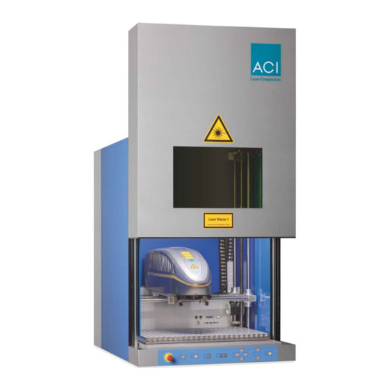
Page 20: View Of The Device
Description View of the Device Front side Workstation COMFORT Workstation PROFESSIONAL la s Kl as sif izi la s er t Kl as sif izi er t DI N DI N 5- 1/ /2 00 5- 1/ /2 00 (1) Safety door... -
Page 21: Rear Side
The workroom also contains the following: • Additional connections • Mounting panel for laser marking device Rear side Variant for laser devices Business CO2 and Economy/Business Diode Workstation COMFORT Workstation PROFESSIONAL (1) Type plate (3) Air conditioner (2) Connections rear side (4) Extraction connector... - Page 22 Description Variant for laser devices Economy/Business Fibre Workstation COMFORT Workstation PROFESSIONAL (5) Type plate (7) Fiber laser cable outlet (6) Connections rear side (8) Extraction connector...
-
Page 23: Interior
Description Interior Interior view, showing the motion axes of the Workstation PROFESSIONAL Technical Specifications Laser marking system Optional: Business CO2 CO Two Marker Economy Diode DPL Smart Marker Business Diode DPL Magic Marker DPL Genesis Marker DPL Nexus Marker DPL Fortis Marker DPL Nobilis Marker DPL Lexis Marker Economy/Business Fibre... -
Page 24: Stroke Length
Workstation PROFESSIONAL Motorised X axis: Linear axis with stepper motor drive Stroke length: 400 mm Usable mounting area of the Workstation COMFORT T-slot plate Width x Depth: 600 mm x 400 mm Workstation PROFESSIONAL Width x Depth: 600 mm x 600 mm... -
Page 25: Maximum Component Height And Marking Fields
Description Maximum component height and Workstation COMFORT marking fields Max. compo- Laser group Objective Marking field nent height Business CO2 CO Two Marker 100 270 mm 50 mm x 50 mm CO Two Marker 150 218 mm 90 mm x 90 mm... -
Page 26: Maximum Working Areas
110 mm x 110 mm F-Theta 254 333 mm 180 mm x 180 mm Maximum working areas Workstation COMFORT The working areas correspond to the physical marking fields of the laser systems (X and Y axes are not possible). Workstation PROFESSIONAL Laser group Objective Max. - Page 27 Description Laser group Objective Max. working area Economy Diode/ F-Theta 100 460 mm x 60 mm Business Diode IR F-Theta 163 510 mm x 110 mm F-Theta 254 580 mm x 180 mm Business Diode GN F-Theta 160 500 mm x 100 mm Business Diode UV F-Theta 162 495 mm x 95 mm...
-
Page 28: Laser Protection Screen
Description Laser group Objective Max. working area Economy/Business F-Theta 100 460 mm x 300 mm Fibre F-Theta 163 510 mm x 350 mm F-Theta 254 580 mm x 390 mm Laser protection screen Width x Height: 450 mm x 300 mm Specification: depends on the type of laser device used laser... -
Page 29: Laser Protection Class
110 V: 16 A Operating conditions Working temperature: 15°C - 35°C Air humidity (rel.): 30% to 85%, not condensing Weight Weight without laser marking device and air conditioner Workstation COMFORT 75 kg Workstation PROFESSIONAL 125 kg Workstation PROFESSIONAL with Y-table 145 kg... -
Page 30: Dimensions
Description Dimensions Workstation COMFORT Length x Width x Height: max. 1078 mm x 760 mm x 712 mm Workstation PROFESSIONAL Length x Width x Height: max. 1278 mm x 760 mm x 1072 mm • Options Rotary module • Workpiece holders •... - Page 31 Description • fixing screws for laser device, • operating instructions. Optional: • Extraction unit with control cable and extraction hose, external, • rotary module, • Y-table, • foot switch. NOTICE Check that the delivery is complete and undamaged. Please contact our service depart- ment if you have any queries.
-
Page 32: Installation
Installation Installation Unpacking fizi la s h DIN (1) Workstation (4) Pallet (2) Lid (5) Fixing screws (3) Carton... - Page 33 Remove the carton (3). Lift the pallet (4) bearing the workstation (1) with a suitable device (such as a lifting truck), and remove the fixing screws (5). NOTICE Weight: Workstation COMFORT 75 kg Workstation PROFESSIONAL 125 kg Workstation PROFESSIONAL with Y-table 145 kg Place the device on a suitable flat surface.
-
Page 34: Setting Up
Installation Setting Up Place the workstation on a stable, flat table. Use a spirit level to check that the workstation is horizontal. It can be adjusted by screwing the four feet in or out as necessary. Check whether the door is aligned parallel to the housing. If necessary, you can adjust the position of the door with the two screws, right (1) and left. -
Page 35: Assembly
Installation Assembly 5.3.1 Connections Rear side Variant Workstation COMFORT and Workstation PROFESSIONAL for laser marking devices Business CO2 and Business/Economy Diode (1) Power switch (2) Auxiliary (3) USB external (4) External start (5) USB interface to the PC (6) Power input... - Page 36 Installation Variant Workstation COMFORT for laser marking devices Business/Economy Fibre (1) Power switch (2) Auxiliary (3) Interlock (4) USB external (5) USB interface to the PC (6) Power input (7) Power output for air conditioner (8) Laser I/O (9) External start...
- Page 37 Installation Variant Workstation PROFESSIONAL for laser marking devices Business/Economy Fibre (1) USB external (2) Power switch (3) External start (4) Extraction (5) Power input (6) USB interface to the PC (7) Interlock (8) Laser I/O (9) Auxiliary (10) Power output for air conditioner...
-
Page 38: Workroom
Installation Workroom (1) Adapter for rotary module (2) USB external (3) Power 1 (4) Power 2 (5) Auxiliary (6) Laser I/O 5.3.2 Laser Marking Device Assembly Fasten the laser marking unit to the mounting panel of the workstation, following the laser marking unit’s operating instructions. -
Page 39: Air Conditioner Assembly
Installation 5.3.3 Air Conditioner Assembly Remove the locking screw from the air conditioner, and screw in the fixing screw. 230 V: Connect the system outlet of the workstation to the power input on the air con- ditioner with the non-heating appliance cable. 110 V: Connect the system outlet of the workstation with the non-heating appliance cable to the power pack supplied, and connect the power pack to the air conditioner. -
Page 40: Checking The Installation
Installation Checking the Installation CAUTION RISK OF PROPERTY DAMAGE. Perform the following tests to avoid material damage. Please check the following points again before you bring your workstation into operation. • Have the mechanical and electrical installations been performed correctly and com- pletely? •... -
Page 41: Operation
Operation Operation Operating and Display Elements Control panel In the setting-up mode, various functions may be controlled using the buttons on the op- erator control panel. (1) Emergency stop button (5) Rotation left/right (2) Open/close door (6) X axis left/right Y axis behind/forward (3) Light on/off (7) Z axis top/bottom... -
Page 42: Emergency Stop Button
DANGER OF INJURIES AND/OR RISK OF PROPERTY DAMAGE. Before releasing the emergency stop button, ensure that the cause of the danger has been rectified! NOTICE After the emergency stop button has been released, the workstation has to be reinitial- ised. Workstation COMFORT... -
Page 43: Start
Operation Start NOTICE Keep to the switching sequence on each start. Start the laser marking device in accordance with the operating instructions. Press the Close door button to initialize the workstation. When the workstation is started up for the first time, you need to enter the settings for the external units in the software. -
Page 44: Switch Off
Operation NOTICE Opening the door breaks the laser safety circuit. NOTICE Detailed information for using the marking software is contained in the provided soft- ware manual. Switch off Press the stand-by button for normal interruptions to operations. Switch the system off with the power switch if the stoppage is going to be lengthy. Switching on again The control PC must be switched on. - Page 45 Operation Problem/Fault Possible cause Elimination Offline Driver not installed Install driver Device not listed in the Device manager Check the USB plug of the operating system Device not switched on Device switched on Axis motions very noisy Axis not greased Grease the axis Foreign body in the path of the axis Clean the axis...
-
Page 46: Maintenance, Repair, Care
Maintenance, Repair, Care Maintenance, Repair, Care All maintenance and repair work except greasing the axles must be performed exclusively by the manufacturer. We recommend you to perform maintenance at intervals of 24 months. The right to claim under warranty is lost as soon as third parties work on or modify the de- vice. -
Page 47: Maintenance Flap
(2) Maintenance flap Unscrew the 3 upper (1) and 3 lower fixing screws from the maintenance flap (2), and re- move the flap. With the Workstation COMFORT, the air conditioner also has to be dismounted, and re- mounted afterwards. Workstation PROFESSIONAL... - Page 48 Maintenance, Repair, Care (1) Air conditioner (2) Mounting surface (3) Fixing screw (4) Condensation water hose (5) 2 holding brackets (6) 4 screws (7) 4 screws Dismounting: Remove the condensation water hose (4). Remove the fixing screw (3). Remove the 4 screws (6) from the holding brackets (5), and remove the air condition- er (1).
-
Page 49: Scrap Disposal
Scrap Disposal Assembly: If dismounted: Screw the two holding brackets (5) tightly to the workstation with 4 screws (7). Fasten the air conditioner (1) to the holding brackets (5) with 4 screws (6). Attach the air conditioner (1) to the mounting surface (2) of the workstation with the fixing screw (3). -
Page 50: Appendix
Appendix Appendix Wiring Diagram Connectors in working area Rear panel CON2 CON1 USB extern USB extern plug type "A" receptacle type "A" cable connector according to IEC130-9 power 1 power 2 binder series 680 CON7 OUT1 (USC) OUT1 (USC) receptacle type "B" upstream to PC OUT2 (USC) OUT2 (USC) - Page 51 Appendix ext. USB Components mounting plate rear wall USB 2.0 upstream power switch workstation 30365028 DSub25M ext. start opt. DSub9 power input power output opt. DSub9 exhauster Components interior PCB Micos adapter 30390058 laser IO ext. USB DSub25F DSub9F power power...
-
Page 52: Drawings Of The T-Slot Plates
Appendix Drawings of the T-Slot Plates 9.2.1 Workstation COMFORT 14,5 A (2 : 5) -
Page 53: Workstation Professional
Appendix 9.2.2 Workstation PROFESSIONAL 14,5 A (2 : 7,5) -
Page 54: Y-Table
Appendix 9.2.3 Y-Table 14,5 561,5 A (2 : 7,5) -
Page 55: Assembly Dimensions
Appendix Assembly Dimensions 9.3.1 Workstation COMFORT for Business CO2 and Economy/Business Diode min. 1118 1138... -
Page 56: Workstation Comfort For Economy/Business Fibre
Appendix 9.3.2 Workstation COMFORT for Economy/Business Fibre 1058 1078... -
Page 57: Workstation Professional For Business Co2 And Economy/Business Diode
Appendix 9.3.3 Workstation PROFESSIONAL for Business CO2 and Economy/Business Diode min. 1050 1267 1287... -
Page 58: Workstation Professional For Economy/Business Fibre
Appendix 9.3.4 Workstation PROFESSIONAL for Economy/Business Fibre 1050 1275 1295... -
Page 59: Drawings Of The Axis Stroke
Appendix Drawings of the Axis Stroke Workstation COMFORT Workstation PROFESSIONAL... -
Page 60: Drawing Of The Rotary Module
Appendix Drawing of the Rotary Module 176,1 ø... -
Page 61: Illustration Of The Working Areas
Appendix Illustration of the Working Areas 9.6.1 Workstation COMFORT with Business CO2 Business CO2 Usable mounting area COTwo Marker 100 COTwo Marker 150 600 mm x 400 mm COTwo Marker 250 Marking field = Working Area Business CO2 COTwo Marker 100... -
Page 62: Workstation Comfort With Economy/Business Diode
Appendix 9.6.2 Workstation COMFORT with Economy/Business Diode Economy Diode/Business Diode IR Usable mounting area F-Theta 100 F-Theta 163 600 mm x 400 mm Business Diode GN F-Theta 160 Marking field = Working Area Business Diode UV F-Theta 162 Economy Diode/Business Diode IR... -
Page 63: Workstation Comfort With Economy/Business Fibre
Appendix 9.6.3 Workstation COMFORT with Economy/Business Fibre Economy/Business Fibre Usable mounting area F-Theta 163 600 mm x 400 mm Marking field = Working Area Economy/Business Fibre F-Theta 163 110 mm x 110 mm Maximum component height Economy/Business Fibre F-Theta 163... -
Page 64: Workstation Professional With Business Co2
Appendix 9.6.4 Workstation PROFESSIONAL with Business CO2 Business CO2 Usable mounting area COTwo Marker 100 COTwo Marker 150 600 mm x 600 mm COTwo Marker 250 Marking field Business CO2 COTwo Marker 100 50 mm x 50 mm COTwo Marker 150 90 mm x 90 mm COTwo Marker 250 150 mm x 150 mm... -
Page 65: Workstation Professional With Economy/Business Diode
Appendix 9.6.5 Workstation PROFESSIONAL with Economy/Business Diode Economy Diode/Business Diode IR Usable mounting area F-Theta 100 F-Theta 163 600 mm x 600 mm F-Theta 254 Marking field Economy Diode/Business Diode IR F-Theta 100 60 mm x 60 mm F-Theta 163 110 mm x 110 mm F-Theta 254 180 mm x 180 mm... - Page 66 Appendix Business Diode GN Usable mounting area F-Theta 160 Business Diode UV 600 mm x 600 mm F-Theta 162 Marking field Business Diode GN F-Theta 160 100 mm x 100 mm Business Diode UV F-Theta 162 95 mm x 95 mm Working area Business Diode GN F-Theta 160...
-
Page 67: Workstation Professional With Economy/Business Fibre
Appendix 9.6.6 Workstation PROFESSIONAL with Economy/Business Fibre Economy/Business Fibre Usable mounting area F-Theta 100 F-Theta 163 600 mm x 600 mm F-Theta 254 Marking field Economy/Business Fibre F-Theta 100 60 mm x 60 mm F-Theta 163 110 mm x 110 mm F-Theta 254 180 mm x 180 mm Working area... -
Page 68: Workstation Professional With Y-Table And Business Co2
Appendix 9.6.7 Workstation PROFESSIONAL with Y-Table and Business CO2 Business CO2 Usable mounting area COTwo Marker 100 COTwo Marker 150 600 mm x 400 mm COTwo Marker 250 Marking field Business CO2 COTwo Marker 100 50 mm x 50 mm COTwo Marker 150 90 mm x 90 mm COTwo Marker 250... -
Page 69: Workstation Professional With Y-Table And Economy/Business Diode
Appendix 9.6.8 Workstation PROFESSIONAL with Y-Table and Economy/Business Diode Economy Diode/Business Diode IR Usable mounting area F-Theta 100 F-Theta 163 600 mm x 400 mm F-Theta 254 Marking field Economy Diode/Business Diode IR F-Theta 100 60 mm x 60 mm F-Theta 163 110 mm x 110 mm F-Theta 254... - Page 70 Appendix Business Diode GN Usable mounting area F-Theta 160 Business Diode UV 600 mm x 400 mm F-Theta 162 Marking field Business Diode GN F-Theta 160 100 mm x 100 mm Business Diode UV F-Theta 162 95 mm x 95 mm Working area Business Diode GN F-Theta 160...
-
Page 71: Workstation Professional With Y-Table And Economy/Business Fibre
Appendix 9.6.9 Workstation PROFESSIONAL with Y-Table and Economy/Business Fibre Economy/Business Fibre Usable mounting area F-Theta 100 F-Theta 163 600 mm x 400 mm F-Theta 254 Marking field Economy/Business Fibre F-Theta 100 60 mm x 60 mm F-Theta 163 110 mm x 110 mm F-Theta 254 180 mm x 180 mm Working area... -
Page 72: Ec Conformity Declaration
EN ISO 13857:2008 EN 349:1993+A1:2008 EN 60204-1:2006+A1:2009 EN 60825-4:2006+A1:2008+A2:2011 Representative for compiling technical documents: Mirko Wunderlich, Steinbrüchenstraße 14, 99248 Grammetal OT Nohra Signed on behalf of the manufacturer: Nohra, 01.02.2019 ACI Laser GmbH Mirko Wunderlich, Geschäftsführer Steinbrüchenstraße 14, 99428 Grammetal OT Nohra... -
Page 73: Index
Index Index Air conditioner ............................21 Air humidity (rel.) ............................29 Axes ................................24 Greasing ............................46 Axis stroke ..............................59 Buttons, active ............................41 Care ..............................15 CE symbol ..............................7 Cleaning ..............................46 Component height ............................. 25 Connection ..............................39 Connection values ............................. - Page 74 Index Electrical data ............................29 Emergency stop button ........................41 Releasing ............................42 Emissions ..............................14 External start ............................. 41 Extraction ............................14 Assembly ............................39 Fault finding ............................... 44 Focus finder function ..........................24 Focus on/off ............................... 41 Foot switch ..............................30 Frequency range ............................
- Page 75 Index Liability ................................. 9 Light on/off ..............................41 Lighting ..............................28 Line-side fuse ............................18 Maintenance ............................15 Manufacturer .............................. 18 Manufacturer address ..........................12 Marking field .............................. 25 Maximum component height ........................25 Maximum working area ..........................26 Mounting area of the T-slot plate ....................... 24 Mounting panel ............................
- Page 76 Technical specifications ..........................23 T-slot plate ..............................20 Mounting area ..........................24 T-slot plate and Y-table ..........................54 T-slot plate for Workstation COMFORT ....................52 T-slot plate for Workstation PROFESSIONAL ..................53 Type plate ............................. 18 Unpacking ..............................32 View of device ............................20...
- Page 77 Index Warning sign .............................. 16 Warranty ............................. 11 Weight ................................ 29 Wiring diagram ............................50 Working area ............................. 26 Working temperature ..........................29 Workroom ..............................20 X-stroke length ............................24 X-Y axis ..............................41 Y-table ............................... 30 Z axis ................................. 41...
- Page 78 Index...
- Page 80 Operating Instructions for Workstation COMFORT/Workstation PROFESSIONAL Article number: 21900012 Version: EN 02/2019-05 ACI Laser GmbH Steinbrüchenstraße 14 D-99428 Grammetal OT Nohra Phone: +49 3643 4152-0 Fax: +49 3643 4152-77 info@ACI-Laser.de www.ACI-Laser.de Mark your territory...
Need help?
Do you have a question about the Workstation COMFORT and is the answer not in the manual?
Questions and answers