aci DLP Series Assembly, Installation And Operation Instructions
Hide thumbs
Also See for DLP Series:
- Installation instructions and owner's manual (12 pages) ,
- Installation & operation instructions (9 pages) ,
- Installation and operation instructions manual (8 pages)
Table of Contents
Advertisement
Quick Links
PRECAUTIONS
R
EMOVE POWER BEFORE WIRING
. D
APPLIED
O NOT ALLOW LIVE WIRES TO TOUCH THE CIRCUIT BOARD
A
N ISOLATION TRANSFORMER IS RECOMMENDED WHEN POWERING THE DEVICE WITH
D
O NOT RUN THE WIRING IN ANY CONDUIT WITH LINE VOLTAGE
F
AILURE TO WIRE DEVICES WITH THE CORRECT POLARITY WHEN USING A SHARED TRANSFORMER MAY
RESULT IN DAMAGE TO ANY DEVICE POWERED BY THE SHARED TRANSFORMER
AUTOMATION COMPONENTS, INC
2305 Pleasant View Road
Middleton, Wisconsin 53562
www.workaci.com
(888) 967-5224
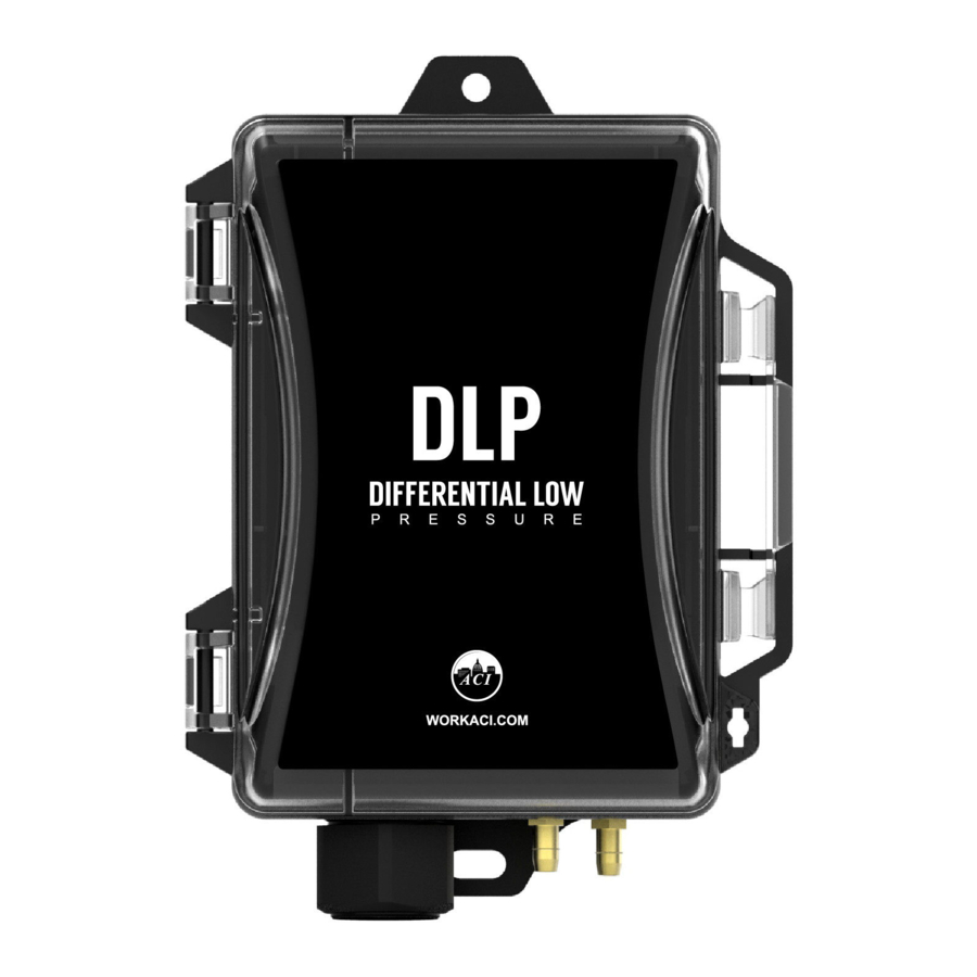
Figure 1: DLP Dimensions and Hardware
Figure 2: DLP with Pitot Tube Option
. N
EVER CONNECT OR DISCONNECT WIRING WITH THE POWER
Page 1 of 5
Installation and Operation Instructions
.
.
DLP Series
24
.
VAC
.
Version : 3.0
I0000777
Advertisement
Table of Contents

Subscribe to Our Youtube Channel
Related Manuals for aci DLP Series


Summary of Contents for aci DLP Series
- Page 1 Installation and Operation Instructions DLP Series Figure 1: DLP Dimensions and Hardware Figure 2: DLP with Pitot Tube Option PRECAUTIONS R EMOVE POWER BEFORE WIRING EVER CONNECT OR DISCONNECT WIRING WITH THE POWER APPLIED O NOT ALLOW LIVE WIRES TO TOUCH THE CIRCUIT BOARD ...
- Page 2 MOUNTING Two size #8 screws are supplied. Mount the unit vertically with the brass fittings pointing towards the ground. Attach the unit to the mounting surface using the two mounting holes located on the top and bottom flanges. DIN RAIL MOUNTING (Optional Accessory Ordered) Attach the DIN Rail Mounting accessory to the back of the enclosure using the 2 screws provided.
- Page 3 C HOOSE DIFFERENTIAL ANGE BASED ON THE EXPECTED DIFFERENTIAL PRESSURE IN YOUR APPLICATION MOVE SWITCHES TO THE CORRECT POSITIONS AND THEN POWER ON THE TRANSMITTER MAXIMUM LINE PRESSURE ACI Part No. Maximum Line Pressure (inWC) DLP-001-W DLP-010-W DLP-040-W The DLP can operate in either unidirectional mode (0 –...
- Page 4 DIP switch SW3 positions 1 and 2 are for Range Selection Note: In Bidirectional mode, a value of 0 PSID will have an output equal to 50% of the full output range. ACI Part No. SW3 Position 1: 1 SW3 Position 1: 2...
- Page 5 Table 2: Product Specifications WARRANTY SPECIFICATION The DLP Series pressure transmitters are covered by ACI’s Five (5) Year Limited Warranty, which is located in the front of ACI’S SENSORS & TRANSMITTERS CATALOG or can be found on ACI’s web site: www.workaci.com.
Need help?
Do you have a question about the DLP Series and is the answer not in the manual?
Questions and answers