Advertisement
Quick Links
LX Switch Stations
Installation Instructions
Hubbell Building Automation, Inc.
9601 Dessau Road • Building One • Suite 100
Austin, Texas 78754
512-450-1100 • 512-450-1215 Fax
www.hubbell-automation.com
Overview
These instructions provide guidelines for setting up, installing, and
programming the LX Switch Station.
Precautions
• RISK OF ELECTRICAL SHOCK. Turn power off at service panel
before beginning installation. Never wire energized electrical
components.
• For installation by a licensed electrician in accordance with
National and/or local Electrical Codes and the following instruc-
tions.
• For indoor use only.
• Read and understand all instructions before beginning installation.
• USE COPPER CONDUCTOR ONLY.
• NOTICE: Do not install if any damage to product is noticed.
Installation
1. Prepare the installation site as necessary. Rough-in wall switch
boxes and route power supply and LON Network leads as neces-
sary. Reference Open System Architecture Communication
Network Section for additional information on the communication
network requirements.
2. Assign Network Address as described in the Assigning Switch
Station Network Address Section.
3. With power off, connect power supply leads (FT Version only)
and LON Network leads to the Switch Station as shown in the
Wiring Diagram.
4. Apply power to the system and verify that the Switch Station's
Power Indicator LED (reference Switch Station Controls Diagram)
is lit.
5. Program Switch Station button controls and lighting system func-
tionality as described in the Programming Switch Station Functions
Section.
Figure 1:
Wiring Diagram
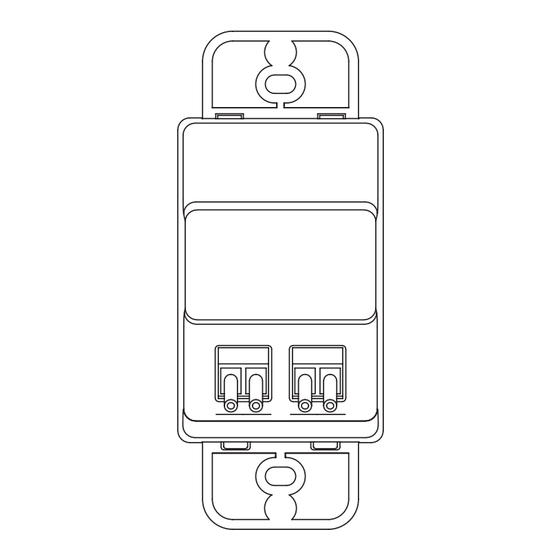
Figure 2:
Switch Station Controls Diagram
Assigning Switch Station Network Address
The Switch Station network address is set via three rotary dials
located under the Switch Station facia (face cover) as shown in the
Switch Station Controls Diagram. Each Switch Station is factory set
to address 001 prior to shipping. For LX-only networks, each Switch
Station on the network will need to be assigned a unique network
address. Addresses must be assigned in sequential order starting with
address 001. For LonWorks Open System Networks, each Switch
Station on the network should be assigned address 000. This will
place the Switch Station(s) into LonMark compatible mode.
To set the Switch Station Address, carefully remove the Switch Sta-
tion facia (front cover) to gain access to the address controls. Insert
a small blade screwdriver into the facia catch release as shown in
the Facia Removal Diagram and gently snap it loose at the top edge.
Remove the facia along with any buttons that obscure the three rotary
dials as shown in the Switch Station Controls Diagram. Rotate the
appropriate dial(s) with the small, blade screwdriver till the indica-
tor points to the appropriate number. Assign each Switch Station its
address as delineated in the project plans as applicable. Dial "A" sets
the most signifi cant digit of the network address and Dial "C" sets the
least signifi cant digit of the network address. For example, address
001 is set by Dial A = "0", Dial B = "0" and Dial C = "1".
Advertisement

Related Manuals for Hubbell LX Series


Summary of Contents for Hubbell LX Series
- Page 1 LX Switch Stations Installation Instructions Hubbell Building Automation, Inc. 9601 Dessau Road • Building One • Suite 100 Austin, Texas 78754 512-450-1100 • 512-450-1215 Fax www.hubbell-automation.com Figure 2: Overview Switch Station Controls Diagram These instructions provide guidelines for setting up, installing, and programming the LX Switch Station.
- Page 2 Touch Tablet Graphical User Interface. For LonMARK Mode Facia Removal Diagram (Address 000), use the LX Switch Station plug-in available from Hubbell Building Automation, Inc at www.hubbell-automation.com to assign the Switch Station button(s) to the lighting circuit(s) and setup schedules and system functionality.
Need help?
Do you have a question about the LX Series and is the answer not in the manual?
Questions and answers