Advertisement
Available languages
Available languages
Quick Links
If you have any questions regarding assembly or if parts are missing, DO NOT return this item to the
store where it was purchased. Please call our customer service number and have your instructions and
parts list ready to provide the model name, part name or factory number:
Or visit our web site 24 hours a day, 7 days a week for product assistance at
THIS INSTRUCTION BOOKLET CONTAINS IMPORTANT SAFETY INFORMATION.
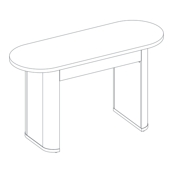
Juliet Oval Desk
Stock # BH3425004710016
# BH3425004710017
# BH3425004710018
ADULT ASSEMBLY REQUIRED
Pacific Standard Time: 8:30 a.m. - 4:30 p.m., Monday - Friday
Or e-mail your request to parts@whalenfurniture.com
PLEASE READ AND KEEP FOR FUTURE REFERENCE.
Date 2024-06-07
1-866-942-5362
www.whalenstyle.com
Rev. 0001-A
LOT NUMBER:
DATE PURCHASED:
/
/
Advertisement

Related Manuals for Better Homes and Gardens Juliet BH3425004710016


Summary of Contents for Better Homes and Gardens Juliet BH3425004710016
- Page 1 LOT NUMBER: DATE PURCHASED: Juliet Oval Desk Stock # BH3425004710016 # BH3425004710017 # BH3425004710018 ADULT ASSEMBLY REQUIRED If you have any questions regarding assembly or if parts are missing, DO NOT return this item to the store where it was purchased. Please call our customer service number and have your instructions and parts list ready to provide the model name, part name or factory number: 1-866-942-5362 Pacific Standard Time: 8:30 a.m.
- Page 2 M A X I M U M R E C O M M E N D E D W E I G H T L O A D S MANUFACTURER: Whalen Furniture Manufacturing CATALOG: Juliet Oval Desk MODEL: BH3425004710016 / BH3425004710017 / BH3425004710018 MAXIMUM LOAD 90.7 kg / 200 lb MAXIMUM LOAD 6.8 kg / 15 lb THIS UNIT IS INTENDED ONLY FOR USE WITHIN THE...
- Page 3 IMPORTANT Before you begin: Open, identify and count all parts prior to assembly. Lay out parts on a flat and non- abrasive surface. You will need the parts identified on page 4 and 5 of this instruction manuals. NOTE: IT IS VERY IMPORTANT TO USE GLUE WITH DOWELS. EXCESS GLUE CAN BE WIPED OFF WITH DAMP CLOTH.
- Page 4 Parts and Hardware List Please read completely through the instructions and verify that all listed parts and hardware are present before beginning assembly. A- Desk Top B- Left Side Frame (Qty. 1) (Qty. 1) C- Right Side Frame D- Back Stretcher (Qty.
- Page 5 Parts and Hardware List Please read completely through the instructions and verify that all listed parts and hardware are present before beginning assembly. (1) 1/4’’ x 15 mm Bolt (2) 1/4’’ x 38 mm Bolt (3) Lock Washer (Qty. 16+1 extra) (Qty.
- Page 6 Assembly Instructions ⑦ x 8 1. Unpack the unit and confirm that you have all the hardware and required parts listed. Assemble the unit on a carpeted floor or the empty carton to avoid any scratch. 2. Securely screw eight Cam Bolts (7) into the designated small holes on the Drawer Front (F) with a Phillips screwdriver.
- Page 7 Assembly Instructions The grooves line up with each other and face inward. ⑥ x 4 3. Orient and position Drawer Right Side Panel (I) onto the cam bolts installed on the Drawer Front (F) as shown. 4. Insert two Cam Locks (6) into the large holes in the Drawer Right Side Panel (I) making sure that the arrow on the face of cam lock faces out and points towards the holes on the closest end.
- Page 8 Assembly Instructions 6. Slide Drawer Bottom Panel (J) into the grooves on the Drawer Side Panels (H and I) until fully inserted into the Drawer Front (F).
- Page 9 Assembly Instructions ⑥ x 4 The cam lock housings face outward. 7. Align and attach the Drawer Supports (K) to the Drawer Front (F) by engaging four Small Cam Locks (6). Turn the cam locks with a Phillips screwdriver until securely locked onto the cam bolts.
- Page 10 Assembly Instructions Groove ⑧ x 8 8. Orient and fasten Drawer Back Panel (G) to both Drawer Side Panels (H and I) and the Drawer Supports (K) with eight 38 mm Pan Head Screws (8). Make sure that the Drawer Bottom Panel (J) fits securely into the groove of the Drawer Back Panel (G).
- Page 11 Assembly Instructions The floor levelers face upward. The cleat faces inward and is flush with the top surface ③ x 2 ④ x 2 ② x 2 9. Orient and attach the Back Stretcher (D) to the Left Side Frame (B) by inserting two 38 mm Bolts with Washers (3 and 4) through the wood cleat and securely screw into place.
- Page 12 Assembly Instructions ③ x 4 ④ x 4 ① x 4 ⑤ x 4 ⑨ x 4 10. Glue four Wood Dowels (5) into the inner holes on the Front Stretcher (E) at both ends. Make sure that you use a small amount of glue with both ends of all dowels. NOTE: It is very important to use a small amount of glue on both ends of dowels and wipe off the excess glue immediately with a damp cloth.
- Page 13 Assembly Instructions Support surface The cut out faces front of the unit ③ x 2 ④ x 2 ① x 2 12. Orient and attach the Front Stretcher (E) to the Left Side Frame (B) with the end wood dowels fully inserted.
- Page 14 Assembly Instructions ③ x 2 ④ x 2 ② x 2 13. Align and attach the Right Side Frame (C) to the Back Stretcher (D) making sure the installed wood dowels on the Front Stretcher (E) fit into the pre-drilled holes properly. Insert two 38 mm Bolts with the Washers (3 and 4) through the wood cleats and securely screw into Right Side Frame (C).
- Page 15 Assembly Instructions ③ x 2 ④ x 2 ① x 2 14. Align and attach the Front Stretcher (E) to the Right Side Frame (C) Insert two 15 mm Bolts (1) with the Washers (3 and 4) through the Metal Brackets (9) installed onto the Front Stretcher (E) and securely screw into Right Side Frame (C).
- Page 16 Assembly Instructions ⑤ x 4 ③ x 1 ④ x 1 ② x 1 15. Position the Table Top (A) upside down on a level and protective surface. 16. Glue four Wood Dowels (5) into the holes drilled on the bottom of Table Top (A). Make sure that you use a small amount of glue with both ends of all dowels.
- Page 17 Assembly Instructions ③ x 4 ④ x 4 ② x 4 19. Insert four 38 mm Bolts (2) with the Washers (3 and 4) through the wood cleats pre-attached onto the Table Top (A) and securely screw into both Side Frames (B and C).
- Page 18 Assembly Instructions ③ x 8 ④ x 8 ① x 8 ⑨ x 4 20. Secure the Side Frames (B and C) to the Table Top (A) by attaching four Metal Brackets (9) over the adjacent threaded inserts with eight 15 mm Bolts (1), eight Lock Washers (3) and eight Flat Washers (4).
- Page 19 Assembly Instructions Ball bearing cart FRONT FRONT Ball bearing cart Drawer Installation Drawer removal 21. Ask for assistance to lift the unit upright and position it near the desired location. 22. Insert the assembled drawer into the frame. Extend the Ball Bearing Slide Tracks on both Side Frame (B and C) all the way forward (including ball bearing cart).
- Page 20 Assembly Instructions Floor leveler 23. Adjust each Floor Leveler as necessary until each Side Frame (B and C) touches the floor and the top is level.
- Page 21 Care and Maintenance Use a soft, clean cloth that will not scratch the surface when dusting. Use of furniture polishes is not necessary. Should you choose to use polishes, test first in an inconspicuous area. Using solvents of any kind on your furniture may damage the finish. ...
- Page 23 NÚMERO de LOTE:__________ FECHA de COMPRA: Escritorio ovalado Juliet Serie # BH3425004710016 # BH3425004710017 # BH3425004710018 ENSAMBLE REQUERIDO POR ADULTO Si tienen alguna pregunta acerca del ensamble o si alguna parte está faltante, no retorne esté producto a la tienda donde lo compro. Por favor llame a nuestro departamento de ayuda al cliente teniendo su instructivo y lista de partes para proveer el modelo, nombre de parte o el número de fábrica: 1-866-942-5362 Hora estándar del Pacífico: 8:30 a.m.
- Page 24 M Á X I M O P E S O R E C O M E N D A D O FABRICANTE: Whalen Furniture Manufacturing CATALOGO: Escritorio ovalado Juliet SERIE: BH3425004710016 / BH3425004710017 / BH3425004710018 CARGA MÁXIMA 90.7 kg / 200 lb. CARGA MÁXIMA 6.8 kg / 15 lb.
- Page 25 IMPORTANTE Antes de comenzar: Abra, identifique y cuente todas las partes antes del ensamble. Coloque las piezas sobre una superficie plana y no abrasiva. Tendrá las partes identificadas en la página 4 y 5 de este manual de instrucciones. NOTA: ES MUY IMPORTANTE EL USO DE GOMA CON LAS CLAVIJAS DE MADERA.
- Page 26 Lista de partes y material de ferretería Por favor lea completamente las instrucciones y verifique que estén todas las partes y partes de ferretería antes de iniciar el ensamblado. A- Tapa del escritorio B- Marco izquierdo (Cant. 1) (Cant. 1) C- Marco derecho D- Soporte posterior (Cant.
- Page 27 Lista de partes y material de ferretería Por favor lea completamente las instrucciones y verifique que estén todas las partes y partes de ferretería antes de iniciar el ensamblado. (1) Perno de 1/4 de pulgada x 15 mm (2) Perno de 1/4 de pulgada x 38 mm (3) Arandela de presión (Cant.
- Page 28 Instructivo de ensamble ⑦ x 8 1. Desempacar la unidad y confirmar que se tiene todo el material de ferretería y partes requeridas. Ensamblar la unidad en un piso alfombrado o en el cartón vacío para evitar rasguños. 2. Atornillar 8 pernos de fijación (7) en los agujeros pequeños designados en el frente del cajón (F) con el desarmador estrella.
- Page 29 Instructivo de ensamble Las ranuras se alinean las unas con las otras y apuntan hacia adentro. ⑥ x 4 3. Orientar y poner el panel derecho del cajón (I) sobre los pernos de fijación instalados en el frente del cajón (F) como se muestra. 4.
- Page 30 Instructivo de ensamble 6. Deslizar un panel inferior del cajón (J) en las ranuras en los paneles laterales del cajón (H y I) hasta que esté completamente insertado en el frente del cajón (F).
- Page 31 Instructivo de ensamble ⑥ x 4 Los espacios de las tuercas de fijación apuntan hacia afuera. 7. Alinear y adjuntar los soportes del cajón (K) al frente del cajón (F) empleando 4 tuercas de fijación pequeñas (6). Girar las tuercas de fijación con el desarmador estrella hasta atornillar en los pernos de fijación.
- Page 32 Instructivo de ensamble Ranura ⑧ x 8 8. Orientar y sujetar el panel posterior del cajón (G) a ambos paneles laterales del cajón (H y I) y a los soportes del cajón (K) con 8 pernos de cabeza redonda de 38 mm (8). Asegurar de que el panel inferior del cajón (J) encaje seguramente en la ranura del panel posterior del cajón (G).
- Page 33 Instructivo de ensamble Los niveladores de piso apuntan hacia arriba. Los tacos apuntan hacia adentro y esten nivelados con la superficie superior. ③ x 2 ④ x 2 ② x 2 9. Orientar y adjuntar el soporte posterior (D) al marco izquierdo (B) insertando 2 pernos de 38 mm con sus arandelas (3 y 4) a través de los tacos de madera y atornillar en su lugar.
- Page 34 Instructivo de ensamble ③ x 4 ④ x 4 ① x 4 ⑤ x 4 ⑨ x 4 10. Pegar 4 clavijas de madera (5) en los agujeros internos en el soporte frontal (E) en ambos extremos. Asegúrate de usar una cantidad pequeña de pegamento en ambos extremos de las clavijas. NOTA: Es importante usar una cantidad pequeña de pegamento en ambos lados de las clavijas y limpiar el exceso de pegamento inmediatamente con una toalla húmeda.
- Page 35 Instructivo de ensamble Superficie de soporte El recorte apunta hacia el frente de la unidad ③ x 2 ④ x 2 ① x 2 12. Orientar y adjuntar el soporte frontal (E) al marco izquierdo (B) con las clavijas de madera finales insertadas completamente.
- Page 36 Instructivo de ensamble ③ x 2 ④ x 2 ② x 2 13. Alinear y adjuntar el marco derecho (C) al soporte posterior (D) asegurando de que las clavijas de madera instaladas en el soporte frontal (E) encaje en los agujeros pre-perforados apropiadamente. Insertar 2 pernos de 38 mm con las arandelas (3 y 4) a través de los tacos de madera y atornillar en el marco derecho (C).
- Page 37 Instructivo de ensamble ③ x 2 ④ x 2 ① x 2 14. Alinear y adjuntar el soporte frontal (E) al marco derecho (C) insertando 2 pernos de 15 mm (1) con las arandelas (3 y 4) a través de los soportes de metal (9) instalados sobre el soporte frontal (E) y atornillar en el marco derecho (C).
- Page 38 Instructivo de ensamble ⑤ x 4 ③ x 1 ④ x 1 ② x 1 15. Poner la tapa del escritorio (A) boca abajo en una superficie nivelada y protectora. 16. Pegar 4 clavijas de madera (5) en los agujeros perforados en la parte inferior de ambos paneles laterales (B y C).
- Page 39 Instructivo de ensamble ③ x 4 ④ x 4 ② x 4 19. Insertar 4 pernos de 38 mm (2) con las arandelas (3 y 4) a través de los tacos de madera pre-adjuntados sobre la tapa del escritorio (A) y atornillar en ambos marcos laterales (B y C).
- Page 40 Instructivo de ensamble ③ x 8 ④ x 8 ① x 8 ⑨ x 4 20. Asegurar los marcos laterales (B y C) a las tapas del escritorio (A) adjuntando 4 soportes de metal (9) sobre los insertos roscados adyacentes con 8 pernos de 15 mm (1), 8 arandelas de presión (3) y 8 arandelas planas (4).
- Page 41 Instructivo de ensamble Carrito de baleros FRENTE FRENTE Carrito de baleros Instalación del cajón Como retirar el cajón Pedir asistencia para poner la unidad en posición vertical y cerca del lugar deseado. Insertar los cajones ensamblados en el marco. Extender los carriles de la corredera de baleros en los paneles laterales (B y C) todo el camino hacia enfrente (incluyendo el carrito de baleros).
- Page 42 Instructivo de ensamble Nivelador de piso 23. Ajustar cada nivelador de piso como sea necesario hasta que cada marco lateral (B y C) toque el piso y la parte superior este nivelada.
- Page 43 Mantenimiento y cuidados Use una toalla suave y limpia para evitar daños y rayaduras. Uso de cera para pulir muebles no es necesario. Si desea usar cera, pruébela en un área que no sea visible para revisar su funcionamiento. ...
Need help?
Do you have a question about the Juliet BH3425004710016 and is the answer not in the manual?
Questions and answers