Advertisement
Quick Links
Advertisement

Related Manuals for Midea CLIVET Ceiling & Floor 2 IF3-XY Series


Summary of Contents for Midea CLIVET Ceiling & Floor 2 IF3-XY Series
- Page 1 CEILING & FLOOR 2 IF3-XY series from 53M to 160M...
- Page 2 INTRODUCTION Dear Customer, Thank you for choosing a CLIVET product. The CEILING & FLOOR 2 model which you have chosen is a high performance product of advanced design and technology, high reliability and quality construction. We suggest that you entrust its management and maintenance to professionally qualified personnel you trust, who, when necessary, only use original spare parts.
- Page 3 INDEX General Details ..........4 4 Maintenance ........... 26 General warnings and safety rules 4.1 Cleaning the indoor unit 1.2 Description of system components 4.2 Cleaning the air filter 1.3 Accessories 4.3 Cleaning the outdoor unit 1.4 Identification 4.4 Repairing refrigerant leaks 4.5 Extended periods of inactivity 2 Installation ............
- Page 4 General Details 1 GENERAL DETAILS General warnings and safety rules WARNING – This manual is the property of CLIVET and reproduction or transfer to third parties of the contents of this document is prohibited. All rights reserved. It is an integral part of the product; make sure that it is always supplied with the appliance, even in case of sale/transfer to another owner, so that it can be consulted by the user or by personnel authorized to carry out maintenance and repairs.
- Page 5 General Details CAUTION DANGER – When connecting refrigerant piping,keep substances or gases other than the specified refrigerant from entering the unit. The presence of other gases or substances can reduce unit performance and cause an abnormal increase in pressure in the refrigeration cycle. This can lead to explosion hazards and resulting injuries. –...
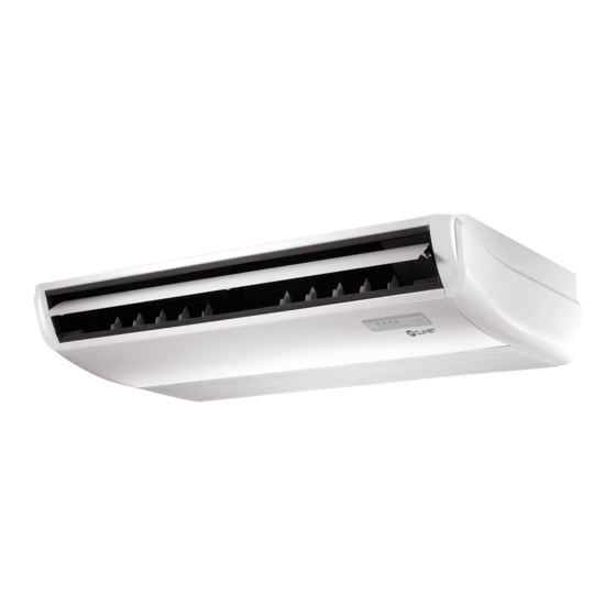
- Page 6 General Details Description of system components Fig. 1 1 Installation element 4 Grille 2 Air outlet 5 Air inlet 3 Ventilation slit 6 Display WARNING The images in this manual are provided for illustrative purposes only. The appearance of your device may differ slightly from the illustrations shown here.
- Page 7 General Details Accessories The air conditioner is equipped with the following accessories. Use all specified installation components and accessories to install it. Incorrect installation may cause water leakage, electric shock and fire, or cause the unit to malfunction. Description Aspect Quantity Indoor unit Installation use and...
- Page 8 General Details Identification The indoor unit and the outdoor unit can be identified by the serial number label that shows the technical and perfor- mance data of the unit and what is required by the legislation in force. Serial number label Indoor unit Fig. 2 CAUTION...
- Page 9 Installation 2 INSTALLATION Installation - preliminary warnings WARNING Product receiving Before installing the indoor unit, consult the label on the product package to check that the The appliance is supplied packed in several parcels. model number matches the model number of Handling must be carried out by appropriate means in the outdoor unit.
- Page 10 Installation Indoor unit installation Type of installation Ceiling Floor 2.4.1 Installation room Refrigerant Minimum Minimum charge surface surface [kg] CAUTION appliance must placed 29.3 well-ventilated room, with a minimum surface 31.0 area that varies according to the amount of 32.8 refrigerant present.
- Page 11 Installation It is PROHIBITED to install the indoor It is PROHIBITED to install the indoor unit in the following locations: unit in the following locations: – in a bathroom or laundry room, because – oil extraction drilling or fracking areas; excess humidity can reduce its service life –...
- Page 12 Installation 2.4.2 Hang the indoor unit Size: Refrigerant piping connection (Gas side) Drain point Refrigerant piping connection (Liquid side) Hook Fig. 4 Length (mm) Indoor unit 1068 1068 105M 1650 1565 140M 1650 1565 160M 1650 1565...
- Page 13 Installation Wood Roof with steel structure Place the wooden assembly panel crosswise over the Install and use the angled steel brackets roof beam, then install the suspension bolts Suspension bolt Wooden assembly panel Angled steel support Roof beam Ceiling Suspension bolts Suspension bolts Fig. 9 Fig. 5...
- Page 14 Installation 7 Assemble the indoor unit. Two people are needed to 9 Assemble the indoor unit on the suspension bolts lift and fasten the unit. Insert the suspension bolts into using suitable locking elements. Place the indoor unit the holes for attaching the unit. Fasten them with the level and check that it is aligned with a spirit level to washers and nuts provided.
- Page 15 Installation WALL INSTALLATION 2.4.3 Preparation for connection pipes It is necessary to make a hole in the wall where the refrigerant piping, drainage pipe and electrical cables that will connect the indoor unit to the outdoor unit will pass through. 1 Determine hole position in the wall according to the position of the outdoor unit.
- Page 16 Installation 2.4.4 Drainage pipe 3 Connect the end of the drainage pipe to the unit’s outlet pipe. Wrap the end of the pipe and securely The drainage pipe is used to drain the water from the fasten it with a hose clamp. unit.
- Page 17 Installation 2.4.5 Configuration with TWIN indoor units UNITÀ INTERNA 1 UNITÀ INTERNA 2 UNITÀ ESTERNA POSSIBLE COMBINATIONS IA3-XY 70M IA3-XY 70M MC3-Y 140T TWIN indoor units are designed to be installed in one room. IA3-XY 105M IA3-XY 105M MC3-Y 160T The controller is used to control the main unit while the secondary unit follows the on/off, set-point, operating mode and fan speed settings.
- Page 18 Installation To use the Y joint, cut the pipe following the diagram in “Fig. 22” to fit the internal and external pipe. CAUTION DANGER – The Y joint must be installed horizontally. Liquid pipes An angle of more than 10° can cause 95 ±10 malfunctions.
- Page 19 Installation TWIN UNIT CONNECTION The 2 indoor units must be connected to the same power supply source. Connect the E, Y, X terminals of both indoor units with shielded cable. Indoor unit 1 Indoor unit 2 Outdoor unit Fig. 24 Outdoor unit power Indoor unit power Signal supply...
- Page 20 Installation 2.4.6 Electrical connections 4 Pass the power cable and the signal cable through the cable outlet. Cables with the following characteristics are required for 5 Connect the U-shaped wire terminal to the terminals. power supply and communication between the indoor Match the colours/labels of the cables to the labels and outdoor units: on the terminal block, then screw the U-shaped wire...
- Page 21 Installation – When the remote switch is OFF (OPEN), the unit will be turned off; – When the remote switch is ON (CLOSE), the unit INDOOR unit terminal block Morsettiera unità INTERNA will be turned on; – When the remote switch is opened/closed, the unit will respond to the request within 2 seconds;...
- Page 22 Installation ALARM 70M - 105M - 140M - 160M models For the input of terminals CN11, CN14 of the new outdoor For the input of ALARM connector CN33 air motor. CN14 Power CN11 Fig. 29 Fig. 31 – The terminal input is set up for ALARM connection, –...
- Page 23 3 USE CAUTION DANGER – If an abnormal condition occurs (e.g. Description of system components there is a smell of burning), turn the unit off immediately and ask the dealer for assistance to avoid the risk of injury, fire or electrocution.
- Page 24 Manual operation (without remote Other functions control) – Automatic restart If the remote control does not work, the unit can be If the power supply to the unit is interrupted, the operated manually with the manual control button unit will automatically restart with the last settings located on the indoor unit.
- Page 25 Remote control ON/OFF MODE Unit switch-on/off button Presents the operating modes in the following order: AUTO » COOL » DRY » HEAT » FAN TEMP Increases the temperature by 1°C at a time. The maximum temperature is 30°C Used to select the fan speed from the following options: TEMP AU →...
- Page 26 Maintenance 4 MAINTENANCE Cleaning the air filter The filter stops dust and other particles from entering the It is good practice to periodically clean both the internal indoor unit. A build-up of dust can reduce the efficiency and external parts of the appliance. This guarantees its of the air conditioner.
- Page 27 Maintenance Cleaning the outdoor unit 4 Extract the air filter as shown (for 140M - 160M models) If the battery in the outdoor unit is clogged, remove the leaves and debris and then remove the dust with a jet of air or water.
- Page 28 Maintenance Extended periods of inactivity Maintenance at the start of the season If you do not plan to use the air conditioner for an extended period of time, proceed as follows: After a long period of non-use, or before a period of frequent use, proceed as follows: Clean all filters Activate the Ventilation mode...
- Page 29 Maintenance Troubleshooting CAUTION DANGER If any of the following conditions occur, turn the unit off immediately. – The power cable is damaged or unusually hot. – You can smell burning. – The unit makes loud or abnormal noises. – A fuse blows or the circuit breaker trips frequently. –...
- Page 30 Maintenance 4.7.2 Anomalies and remedies If problems occur, please check the following before contacting a service centre. Anomalies Possible causes Remedies The set temperature may be higher than Set a lower temperature the room temperature The heat exchanger of the indoor or Clean the heat exchanger (Service Centre) outdoor unit is dirty Remove the filter and clean it following...
- Page 31 Maintenance Error codes displayed on the indoor unit display Error code Cause Timer light EH 00 / Indoor unit EEPROM parameter error EH 0A EL 01 Indoor / outdoor unit communication error EH 03 The indoor fan speed is operating outside of the normal range(for some models) EH 60 Indoor room temperature sensor T1 is in open circuit or has short circuited EH 61...
- Page 32 Maintenance ERROR CODES DISPLAYED ON THE REMOTE CONTROL. Use the “Query mode” function on the remote control to display the alarms (see: technical manual special modes). Error code Description EH 00 / Indoor unit EEPROM parameter error EH 0A EL 01 Indoor / outdoor unit communication error EH bA Communication error between indoor unit and indoor external fan module...
- Page 33 Maintenance PC 02 Top temperature protection of compressor or High temperature protection of IPM module PC 40 Communication error between outdoor main chip and compressor driven chip PC 41 Current Input detection protection PC 42 Compressor start error PC 43 Lack of phase (3 phase) protection PC 44 Outdoor unit zero speed protection...
- Page 34 Disposal 5 DISPOSAL The manufacturer is registered on the National EEE Register, Professional WEEE: all WEEE which comes from something in compliance with implementation of Directive 2012/19/EU other than private households. and pertinent national regulations on electrical and electronic This equipment may contain: equipment waste.
- Page 35 Attachments 6 ATTACHMENTS Indoor unit wiring diagrams (53M)
- Page 36 Attachments Declaration of conformity DECLARATION OF CONFORMITY EU DICHIARAZIONE DI CONFORMITÀ UE KONFORMITÄTSERKLÄRUNG EU DECLARATION DE CONFORMITE EU DECLARACIÓN DE CONFORMIDAD EU E DECLARE UNDER OUR SOLE RESPONSIBILITY THAT THE MACHINE ICHIARIAMO SOTTO LA NOSTRA SOLA RESPONSABILITÀ CHE LA MACCHINA IR ERKLÄREN EIGENVERANTWORTLICH, DASS DIE ASCHINE OUS DÉCLARONS SOUS NOTRE SEULE RESPONSABILITÉ...
- Page 37 Attachments...
- Page 38 FOR 30 YEARS WE HAVE BEEN OFFERING SOLUTIONS FOR SUSTAINABLE COMFORT THE WELL-BEING OF PEOPLE AND THE ENVIRONMENT www.clivet.com sales and service CLIVET SPA Via Camp Lonc 25, Z.I. Villapaiera 32032 Feltre (BL) - Italy Tel. +39 0439 3131 - Fax +39 0439 313300 info@clivet.it...
Need help?
Do you have a question about the CLIVET Ceiling & Floor 2 IF3-XY Series and is the answer not in the manual?
Questions and answers