Advertisement
Quick Links
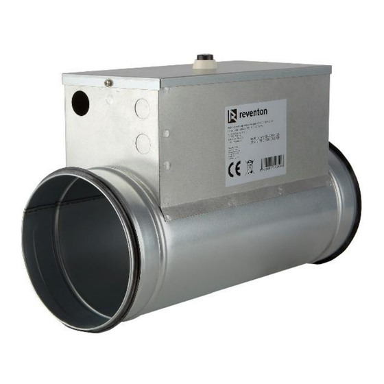
1-step electric duct heater with
controlling
Technical documentation
1. Technical parameters:
V/Hz: 230/50
Set temperature range, °C: -10 - 30
Ambient temperature, °C: -30 - 50
Min. airflow,
Model
HEATER 150/1.2
HEATER 200/2.4
HEATER 250/2.4
HEATER 250/3.6
2. Construction:
The body of electric heater is made of galvanized plate which is
good at high temperature resistance, heat reflection rate and
corrosion resistance. There are two rubber seal ring installed at
the end of the electric heater to make it easier to be connected
with other ducts.
3. Installation:
The length of a straight pipe connecting the heater and an unit
should be a bit higher than the distance to temperature sensor
which should be equal or higher than three times diameter
of this pipe (like it is shown on the picture below). The heater
should be installed with the electrical box facing upwards.
IP protection rating: 40
Nominal
Heating
current,
power,
m
3
/h
A
120
5.3
180
10.6
265
10.6
375
15.9
4. Operation:
The heater enables to achieve the required temperature of air
after the heater (in the direction of airflow). It is realised by
constant comparison of temperature measured by the
temperature sensor with the one set by user with the
temperature knob. Based on the difference, the controlling
system of the heater adjust the heating capacity of the heater
to achieve and maintain the required air temperature. It uses
PWM method for it.
Moreover, in case of using item as a preheater, it is
recommended to mount NTC temperature sensor in the
exhaust duct and set temperature on the knob to 5°C.
5. Thermal protection:
All models are equipped with two-stage of temperature
protection: automatically recover of 50℃ temperature control
switch and manual recover of 100℃ temperature control
switch.
Moreover, in case of connection to INSPIRO or VERTIC,
if INSPIRO's or VERTIC's driver detects fan error,
connected heater would be turn off.
Attention: Before manually resetting the temperature control
switch, the reason for the action of the temperature control
switch should be found out, and the heater should be powered
on again after the fault is eliminated.
It must be ensured that the heater should not work if the
average speed of the air flows through its is less than 5 m/s. For
kW
this purpose can be used a differential pressure switch which
1.2
detects the lack of the airflow and turns off the heater or the
2.4
heater operation can be coupled with a fan operation causing
2.4
the airflow.
3.6
6. Sensors:
For proper operation of the heater, the NTC temperature
sensor must be connected. It is included in the set with the
heater.
Moreover, there is an opportunity of applying an external
differential pressure switch, which would prevent turning on
the heater if there is no airflow. Such equipment should be
installed in way measuring the pressure difference between
sucking and blowing pipes). It is not included in set, its usage is
optional.
7. Indicators:
There are three indicators located on PCB (see the diagram in
point 9). The indicators tell about the state of the heater, i. e.:
D5 – fault indicator - it tells about a fault; if it is on, there is a
problem with the differential pressure switch (if connected) or
with the SCR; if the indicator is blinking, the probable cause is a
short circuit of the SCR
D6 – power indicator - it tells that the heater is powered by
electricity; it should be always on if the unit is supplied
D7 – heating indicator – it tells about the PWM duty cycle; it
could steady on (if the duty cycle is 100%), steady off (if the duty
the
Advertisement

Subscribe to Our Youtube Channel
Related Manuals for REVENTON HEATER 150/1.2


Summary of Contents for REVENTON HEATER 150/1.2
- Page 1 5 m/s. For this purpose can be used a differential pressure switch which HEATER 150/1.2 detects the lack of the airflow and turns off the heater or the 10.6 HEATER 200/2.4...
- Page 2 (at least two times per year). 8. Dimensions & Weights: Weight, kg ØD, mm H, mm Model 1.85 HEATER 150/1.2 2.40 HEATER 200/2.4 2.75 HEATER 250/2.4 3.15 HEATER 250/3.6 9. Wiring diagram: WARNING: Please arrange the professional technician to install this product according to installation drawing and instruction.
Need help?
Do you have a question about the HEATER 150/1.2 and is the answer not in the manual?
Questions and answers