Advertisement
Quick Links
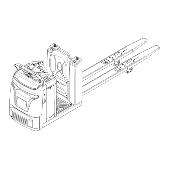
LOW-LIFT ORDER PICKER
SERVICE MANUAL
WARNING
Do not operate the tow order picker before reading
and understanding the operating instructions.
NOTE:
Please check product type and parameters of your
truck in this manual as well as on the ID-plate.
Keep this instruction manual for future reference.
25EO-X
Advertisement

Related Manuals for Hyundai 25EO-X


Summary of Contents for Hyundai 25EO-X
- Page 1 25EO-X LOW-LIFT ORDER PICKER SERVICE MANUAL WARNING Do not operate the tow order picker before reading and understanding the operating instructions. NOTE: Please check product type and parameters of your truck in this manual as well as on the ID-plate.
- Page 2 FOREWORD Before operating the order picker, please read this instruction manual carefully and understand the usage of the truck completely. All instructions in this manual should be seriously followed, otherwise warranty will be invalid by default, and our company shall not be liable for any losses arising therefrom. If the customer or a third party modifies the order picker without manufacturer's permission, the warranty will be invalid by default, and our company shall not be liable for any loss arising therefrom.
- Page 3 Contents CORRECT APPLICATION ............................. 8 DESCRIPTION OF THE ORDER PICKER ........................ 9 Definition of directions ..........................9 Overview of the main parts ......................... 10 Main technical data ............................. 11 Description of the safety devices and warning stickers................13 Identification plate (ID plate) ........................13 WARNINGS, RESIDUAL RISK AND SAFETY INSTRUCTIONS ................
- Page 4 Safety Instructions, Warning Indications and other Notes................37 Drive/brake system ............................43 Overview ..............................43 Brakes ................................47 10. Hydraulic system ............................. 48 Overview ..............................48 Hydraulic circuit ............................50 TROUBLESHOOTING ............................ 51 11. REGULAR MAINTENANCE ..........................53 Maintenance checklist ..........................53 Lubricating points ............................
- Page 5 1. CORRECT APPLICATION The order picker described in this manual is standing low-lift order picker , which possess functions such as: electrically powered low lift of forks, electrically powered lift of man-up platform (optional), electrically powered walking and steering, and electromagnetic braking. It is only allowed to use the order picker following the instructions of this manual.
- Page 6 2. DESCRIPTION OF THE ORDER PICKER Definition of directions Definition of directions Note Front Driving side Rear Loading side Left Right...
- Page 7 Overview of the main parts...
- Page 8 Description Description Entry-roller Chassis ○ ● Tandem load wheels Lead-acid battery ● ● Single load wheel Lithium battery ○ ○ Exit-roller Rubber mat ○ ● Fork Platform ● ● Backrest Platform (man-up) ● ○ Right cover Storage compartment ● ● Tiller Fender ●...
- Page 9 Type sheet for industrial order picker according to VDI 2198 25EO-X Model Electric Drive Order pickers Manual,pedestrian,stand-on,seated,order picker operation Q(kg) 2500 Load capacity/rated load C(mm) 1200 Load center distance Load distance X(mm) 1535 Wheelbase Y(mm) 2723 Net weight without battery...
- Page 10 Description of the safety devices and warning stickers For the USA market, the description of the safety and warning labels is mentioned in chapter 11. Capacity sticker Identification plate (ID plate) Crane hook sticker Hydraulic oil adding sticker The order picker is equipped with 3 emergency buttons (23), pressing any one of the three buttons can turn off all the functions of the order picker .
- Page 11 This order picker is not designed to be water-resistant, do not operate it outdoors in rainy days. If the order picker has malfunctions, check chapter 6 for details. 4. COMMISSIONING, TRANSPORTING, DECOMMISSIONING Commissioning 25EO-X Type 1400 Commissioning weight [kg] Around...
- Page 12 Lift The operation of loading and unloading to the order picker shall be carried out only by personnel that has been trained in operation of fixing and lifting tools. Use specific cranes and lifting equipment. Equip yourself with protective equipment when the crane is working.
- Page 13 items before operation. DO NOT USE THE order picker IF ANY MALFUNCTION IS FOUND. • Check for scratches, deformation or cracks. • Check if there is any oil leakage from the cylinder. • Check the vertical creep of the order picker. •...
- Page 14 enter the mode of password entry. At this time, enter a 4-digit-code in turn and press "√" button, the password entry is successfully done if the buzzer rings once. Pin-code lock can support up to 10 sets of passwords. After recording 10 sets of passwords, the newly entered passwords will be overwritten one by one from the first set, please save the passwords that have been set.
- Page 15 Please carefully drive the order picker to your destination, watch the route conditions and adjust the driving speed via the accelerator knob operation. Press "turtle speed" button (31) to activate the turtle speed function. The indicator turns red and the maximum speed of the order picker decreases;...
- Page 16 Stomp the pedal switch (33) twice quickly and hold on, the platform can be lowered by this way. The platform stops lowering if the pedal switch (33) is released. Steering Steer the order picker by moving the tiller (7) to left/ right side. Left/ right rotation limit of the tiller is 60°, corresponds to the 90°left/ right rotation limit of the drive wheel.
- Page 18 7. Controllers and related devices a. Controller appearance This section uses ACE0 as an example. For details about other controllers, see the parts manual...
- Page 19 Item Description Item Description Holder Fuse 30A Flat Washer Φ5 Screw M8x16 Spring Washer Φ5 Screw M4x12 Screw M5x12 Screw M4x6 Contactor Holder Screw M5x8 Contactor Fuse Holder Screw M6x30 Flat WasherΦ4 Spring Washer Φ6 Fuse 200A Screw M6x25 Copper Busbar Flat WasherΦ6 Copper Busbar Controller...
- Page 20 b. Wiring/circuit diagram Standard 20 CE(Lithium battery)circuit diagram...
- Page 21 Code Name Code Name Password lock Traction controller SM1、SM2、SM3 Stop switch Limit switch FU02 Fuse15A Fuse30A Main contactor Elec. brake Fuse350A Traction motor Main contactor Position sensor FU01 Fuse10A Potentiometer Li Battery Li Battery Capacitance Warning lamp Horn Blue lamp Steering controller S1、S2、S3、S4 Dot switch...
- Page 22 b-2 Standard 20 CE(Lead-acid battery)circuit diagram...
- Page 23 Code Name Code Name Password lock Traction controller SM1、SM2、SM3 Stop switch Limit switch FU02 Fuse15A Fuse30A Main contactor Elec. brake Fuse350A Traction motor Main contactor Position sensor FU01 Fuse10A Potentiometer Battery Capacitance Warning lamp Horn Blue lamp Steering controller S1、S2、S3、S4 Dot switch HL10、HL11 Headlamp...
- Page 24 Platform lifting 20 CE(Lithium battery)circuit diagram...
- Page 25 Code Name Code Name Password lock Traction controller SM1、SM2、SM3 Stop switch Limit switch FU02 Fuse15A Fuse30A Main contactor Elec. brake Fuse350A Traction motor Main contactor Position sensor FU01 Fuse10A Potentiometer Li Battery Li Battery Capacitance Warning lamp Horn Blue lamp Steering controller S1、S2、S3、S4、S5 Dot switch...
- Page 26 Platform lifting 20 CE(Lead-acid battery)circuit diagram...
- Page 27 Code Name Code Name Password lock Traction controller SM1、SM2、SM3 Stop switch Limit switch FU02 Fuse15A Fuse30A Main contactor Elec. brake Fuse350A Traction motor Main contactor Position sensor FU01 Fuse10A Potentiometer Battery Capacitance Warning lamp Horn Blue lamp Steering controller S1、S2、S3、S4 Dot switch HL10、HL11 Headlamp...
- Page 28 c. Test and troubleshoot Fault codes can be viewed directly in the dashboard, or the current fault information can be viewed with a handheld programmer. Test A. Controller Measure the diode voltage of the AC MOSFET (ZAPI for example) circuit in the controller, and check whether it is burnt or damaged.
- Page 29 Test 2: measure the diode voltage to u, V and W with red lead, and B + with black lead. Note: The multi-meter pointer cannot be reversed B. line contactor and fuse measurement For line contactors and line fuses, connect an ohmmeter (multi meter set to Ohm) at the point shown in the figure and check that it measures the specified value.
- Page 30 8. BATTERY MAINTENANCE, CHARGING AND REPLACEMENT Only trained technicians are allowed to maintain, charge or replace the battery. Recycling of batteries undergoes national regulations. Please follow these regulations. Protect batteries away from open fire for battery disposal, otherwise it will cause explosion. ...
- Page 31 Replacement Take out the battery and place it on the equipment for battery replacement safely, and ensures that the battery replacement device does not move during the battery replacement. Incorrect use of the device may cause the battery being tipped over! To remove the battery, press lock catch (34) and lift the tiller (7) to open the console.
- Page 32 Battery indicator The left side of the figure above is the main interface of the Indicator, which contains the battery power display, cumulative working hours and driving speed. The right side of the above figure is the fault interface, which contains the fault code. When the remaining battery power is 10%-19%, the battery column changes from green to yellow.
- Page 33 Battery Label Item Description Identification plate Bar code and two-dimensional code Warning Label Identification plate and Warning label Description Item Description Manufacturer logo Rechargeable logo Battery model Vertical upward packing, transportation Nominal voltage of battery No putting into ordinary garbage bins Rated capacity of battery No long-term exposure to sunshine Battery energy of battery...
- Page 34 Outline diagram (24V 200Ah as an example) Safety Instructions, Warning Indications and other Notes Safety regulations for handling lithium-ion batteries Do not try to make any repairs or servicing of lithium batteries Risk of electric shock and burning The battery’s charging and discharging connectors have open terminals, avoid any body contacts, contamination or direct contacts with objects which can cause short circuit connection of terminals.
- Page 35 Proper use of charger or use of wrong charger can cause damages to a battery or charger. Follow the required charger specifications; If the operation voltage of the charger is out of the applicable voltage range, the charger or battery may be damaged causing serious safety risks. The charger in use must be approved by the battery (truck) manufacturer.
- Page 36 • Do not store in places with valuable objects and close to valuable objects. • A Class D fire extinguisher must be available on demand. • There should not be any fire or smoke detectors in the storage area in order to ensure that an automatic fire detection system is only activated in the event of actual danger (e.g.
- Page 37 escaping gases, debris as well decomposition products of certain chemicals. These combustion products are substances that enter the body through the respiratory tract and/or the skin can produce and adverse effects such as choking. Avoid contact with combustion products. Use protective equipment. Special firefighting protective equipment Use self-contained breathing apparatus.
- Page 38 Wear personal protective equipment. If vapors, dust or aerosols are presented use self-contained • breathing apparatus. Precautionary measures for the environment Do not allow spilled fluids to enter the water system, drainage system or the underground water. Cleaning measures The leaked fluid must be removed professionally following the related protocols. Battery lifetime and maintenance The lithium-ion batteries are maintenance-free.
- Page 39 Do not open, damage, drop, penetrate or deform the battery. • Do not throw the battery into a fire. • Protect the battery from overheating. • Protect the battery from direct sun light. • • Follow storage and charging procedures Failure to comply with these safety instructions can result in fire and explosion or the leakage of harmful materials.
- Page 40 9. Drive/brake system a. Overview The drive/brake system includes the following: 1) The drive motor controlled by the controller transmits the rotating power to the drive shaft (electric-mechanical power) 2) The drive shaft converts the rotational power transmitted from the drive motor through its gear set into the torque and speed suitable for the drive, and sends it to the corresponding wheels (mechanical power).
- Page 41 Item Description Qty. Note Screw M8x30 Spring Washer 8 Motor Baffle Screw M8x20 Steering Unit WheelΦ250x82 Proximity Switch Spring Washer 10 Screw M10x30 Brake Operation Potentiometer kit 20CE Optional The drive motor runs when the following conditions are met: Screw M6x16 13.01 1 Open the emergency stop switch, start the power supply, unlock the code lock, and power the vehicle...
- Page 42 3) Then remove the screws connecting the motor with the car body...
- Page 43 3) Remove the screw and take off the motor power cord connector 4) Remove and replace the 5 screws fixing the PU ring with a 17mm wrench 5) The reverse process of installation and disassembly...
- Page 44 b. Brakes Appearance Brake removal and installation Remove the brake by removing the three screws that are fixed to the drive wheel with a 5mm hex wrench. The reverse process of installation and disassembly...
- Page 45 10. Hydraulic system Overview The hydraulic system is composed of working oil pump, lifting oil cylinder, pipeline and other parts. The hydraulic oil is supplied by the oil pump directly connected with the motor. The oil pump sends the hydraulic oil to the cylinder.
- Page 46 Hydraulic oil circulation The hydraulic oil tank stores hydraulic oil, which is supplied to the main hydraulic pump through a filter. The main hydraulic pump pressurizes the supplied oil and sends it to the lifting cylinder. When hydraulic oil is received, these systems perform their functions and then drain the waste oil to the tank through the return filter.
- Page 47 Hydraulic circuit Lift cylinder Lowering valve Pressure valve Throttle valve Hydraulic power pack (motor and pump) Oil tank...
- Page 48 TROUBLESHOOTING Pump Motor Trouble Possible cause Poor connection or blown fuse. Check the battery connection. Check the key fuse. Check whether the fuse of the hydraulic pump motor may be blown. Key switch, upper limit switch and line contactor are not closed. Turn off the key switch.
- Page 49 Air leaks into the inlet line. The oil level is low. The oil passage is restricted. The oil is too thin. The oil temperature is too high. Air leakage exists in the system. The pump is too worn. system operates under high pressure.
- Page 50 11. REGULAR MAINTENANCE Only qualified and trained personnel are allowed to do maintenance on this truck. • Before maintaining, remove the load from the forks and lower the forks to the lowest position. • • If you need to lift the order picker, please use the specific binding equipment or lifting equipment mentioned in Chapter 4.
- Page 51 22 Check the contactor(s) • 23 Check the frame leakage (insulation test) • 24 Check function and mechanical wear of the accelerator • 25 Check the electrical system of the drive motor • Braking system 26 Check brake performance, if necessary replace the brake disc or adjust the air gap •...
- Page 52 Check and refill hydraulic oil The required hydraulic l type is: • H-LP 46, DIN 51524 Viscosity is 41.4 – 47 • Oil filling level: 1.5L for standard order picker, 3.0L for optional order picker with man-up platform • Checking electrical components and fuses Remove the front panel, the fuses are located as shown in the following figure.
- Page 53 Fuse Specification 350 A 30 A 200 A FU01 10 A FU02 15 A...
- Page 54 12. TROUBLE SHOOTING Fault Possible cause Solution Battery connector is not connected Check and well-connected the well connector The emergency switch is pressed Release emergency switch The truck cannot The pin-code lock is not activated Activate the pin-code lock move Check SOC and must charge the Low battery battery...
- Page 55 13. The CURTIS control system a. The Curtis handheld programmer INTRODUCTION The Curtis 1313 Handheld Programmer (1313 HHP) performs programming and troubleshooting tasks for Curtis programmable motor controllers, gauges, and control systems. The 1313 HHP connects to Curtis devices in one of two ways—specific to the device: Either directly via the device’s RS232 serial port, or through a Controller Area Network (CAN) connection which can have multiple devices on the CAN bus.
- Page 56 This manual, RevC July 2022, is updated for the following 1313 HHP software. Consult the Application Note: 1313 HHP Software Update, RevG (pdf) for the software matching the revisions shown. Update to both the Serial and CAN (this manual) software versions as illustrated below.
- Page 57 Controller (Vehicle System) Connector 1313-xx31 Wiring D-Sub Pin Function CAN_H CAN_L B+ (8–36 V) B– Vehicle Harness Wiring for CAN Connected 1313 HHP...
- Page 58 POWER-ON THE 1313 HHP Connect the 1313 HHP to the system by plugging it into the system’s CANbus using the supplied DB9 CAN-port cable. If the CAN connection point provides power, the 1313 HHP will automatically power up. If not, press the power key ) and it will power up and run off its internal batteries (if batteries are installed).
- Page 59 DISPLAY FORMAT The high-resolution clarity of the LCD screen allows a wealth of information to be displayed at once. The example below shows the information available in the Main Screen. green circle ( ) indicating online mode Red slash ( ) indicating offline mode icon indicating...
- Page 60 In this above example, pressing the “Select” softkey will open the highlighted Programmer app. The “Select” softkey opens whichever app is highlighted. Pressing the "Offline" softkey switches the 1313 HHP to Offline mode. In Offline Mode, the 1313 HHP cannot communicate with the device. The 1313 HHP can perform operations that do not require communication with the device.
- Page 61 Soft keys These three keys are blank because their function is context-specific. At any given time, their function is shown directly above them on the LCD screen. The symbol “»” indicates more options. Pressing the softkey under the “»” will scroll to another set of softkey options.
- Page 62 Screenshots Momentarily press the Power Key and then momentarily press the Favorites key to save the present image of the LCD display. These are called screenshots. Main Screen Pressing this key will return the 1313 HHP to the Main Screen from any location. When the main screen is displayed, use this key to cycle through the individual apps.
- Page 63 c. DEVICE Device Details and Connection To use the 1313 HHP, a device must be compatible and then a CAN connection established. The Device app is where devices (CAN nodes) discovered during the startup CANbus-scan are listed*. After the 1313 powers up and completes the start -up scan, the Main Screen is displayed with the Devices app highlighted.
- Page 64 (1) 1313 HHP startup-scan of CANbus for devices (2) Main Screen following the CANbus scan Just the “Offline” capable apps are available. (3) “Select” softkey—opens app and lists devices (4) “Details” softkey—returns device information (5) “Connect” softkey—receiving data progress (6) Device connected—all apps are available...
- Page 65 d. PROGRAMMER The Programmer* app is where parameters, monitor variables, active-faults, and the fault -history are accessed. There are no separate monitor and diagnostics apps on the main screen. This chapter covers all of the items that can be accessed with the Programmer. It is recommended that the Device manual be consulted for explanations of the read/write and read only variables viewable within Programmer.
- Page 66 PROGRAMMER STRUCTURE When any of the app’s top-level menus are selected ( ) the name of the app is displayed adjacent to the Programmer icon. When navigating through a hierarchical menu, the text at the top of the screen expands to show the path taken. Likewise, the item’s relative position on the screen or in a menu is shown in the window.
- Page 67 ADJUSTING/EDITING PARAMETERS Within Programmer, use the down ( ) or up ( ) arrows to navigate between parameters, monitor-items, or sub-menus. If the menu contains more than the 8 items shown on the screen, a scrollbar appears at the right edge of the screen. When a scrollbar is present, the lines wrap around so that navigating up from the top line/item navigates the screen to the last line/item on the list and vice versa.
- Page 68 e. Trouble shooting for Curtis system (Curtis-F4-A) Fault Name Description Cause or solution meter/c ontroller displays the fault code Controller Overcurrent Turn off motor, Fault Type: 1, the motor U, V, W phase external main contactor, 1 = U-phase overcurrent connection short circuit electromagnetic 2 = W phase overcurrent...
- Page 69 1, the controller works in extreme environments 2. The load is too heavy Turn off motor, 3. The controller installation is main contactor, unreasonable electromagnetic 4. Check the temperature displayed by Controller Severe Overtemp brake, Programmer System Monitor Menu accelerator, full Controller Controller Temperature power electric By lowering the temperature to below 95...
- Page 70 Turn off motor, 1, the battery voltage to the KSI (pin1) main contactor, terminal of the controller exceeds the electromagnetic severe high voltage set point Severe KSI Overvoltage brake, 2, Check the voltage displayed by accelerator, full Programmer System Monitor Menu power brake Controller Keyswitch Voltage 1, motor speed has been detected...
- Page 71 (>100) An ill-formed or electromagnetic corrupted application brake, package was loaded accelerator, into controller. interlock, drive 1, drive 2, drive 3, drive 4, drive 5, drive 6, drive 7, proportional drive, oil pump, coil power supply, full power braking 1-12 OS General 2 (<100) Internal Fault.
- Page 72 1. The battery needs to be charged, and the performance of the controller is limited at this voltage 2. The controller battery parameter setting is wrong 3. Non-controller systems consume photocells 4. The internal resistance of the battery is too high Reduced drive Undervoltage Cutback 5.
- Page 73 "Ext 12V Supply Failure" 1, the external 12V load is too small Fault type: (pin23) 1. The output 12V voltage is Turn off the 12V 2. Check the voltage and current of the out of range output 12V output displayed by Programmer / 2.
- Page 74 Closes the Lower Fault currently Equivalent to Driver 1 Fault assigned driver 1. The motor encoder fails Encoder Fault 2. Crimping or wiring error Fault Type: Turn off the 3. Check Programmer / System Monitor 1. Verify the loss electromagnetic Menu / AC Motor / Motor RPM 2.
- Page 75 1, the accelerator input voltage is out of the range of Analog Low and Analog High settings, and the corresponding Throttle Input Failure. analog input is defined as the Fault Type: Turn off the accelerator input 1. The outside is too low or accelerator 2.
- Page 76 Oil Pump High Pedal Wrong lift/descent accelerator input condition (>25%) Protection (Pump HPD) Fault Type: Turn off the oil Setting Parameter Error: 1, just lifting pump 1. Hydraulic suppression type 2, just go down 2. HPD/SRO judgment time 3. Lifting and descending Hardware failure of oil pump accelerator Turn off the motor, main...
- Page 77 PDO Fault 1220 Turn off the 1.1220E Steering controller motor, main communication data is not sent to the contactor, controller for more than 500ms, check electromagnetic the CAN communication brake, accelerator, and brake at full power No steering, turn 1. The 1220E controller sends a critical off the motor, fault message and notifies the running main contactor,...
- Page 78 Turn off the 1. If the communication data of the motor, main lithium battery is not sent to the contactor, controller for 1S, check the CAN electromagnetic communication PDO Timeout BMS brake, accelerator, and brake at full power Limited operation 1 Lithium battery over temperature BMS Temp High fault Drive Current Li...
- Page 79 Inch Foot Pedal Fault Turn off the 1. Run time fault is defined by VCL, motor, main refer to system information contactor, 2, when using VCL to control the drive, electromagnetic the drive command does not match the brake, drive letter accelerator, interlock, drive 1, drive 2, drive 3,...
- Page 80 drive, full power braking Turn off the motor, main contactor, electromagnetic brake, accelerator, Supervision Input Check Faulty internal controller interlock, drive 1, drive 2, drive 3, drive 4, drive 5, proportional drive, full power braking 1, too many data bits are allocated during PDO mapping, or the target is incompatible PDO Mapping Error...
- Page 81 76 low pressure reduction power 77 High pressure reduction 78 without encoder signal 79 current check out of range 80 current check out of range 81 can detect encoder signals, but cannot automatically detect the number of pulses per revolution (encoder steps) 82 Automatic matching failed The 90/98 does not detect the permanent magnet...
- Page 82 Turn off the 1, the encoder step count setting does motor, main not match the reality contactor, 2. Check the verification parameter electromagnetic settings Programmer AC Motor Setup Encoder Pulse Error brake, Quadrature Encoder/ Encoder Steps accelerator, and 3. The motor loses IFO control, and the brake at full motor accelerates and rotates without power...
- Page 83 Parameter mismatch Fault Type: Turn off the 1. The dual-wheel drive motor, main 1. Incorrect motor feedback selection for function is turned on in torque contactor, different motor technology applications mode electromagnetic 2. The dual-wheel drive function is 2, SPMSM motor feedback brake, turned on in torque mode selected encoder...
- Page 84 10-2 Driver 2 Fault Fault Type: 1, The driver load is open or short 1. Drive short circuit 2. The connector pin or contactor coil is 2. Drive overcurrent dirty 3, open/short circuit (detected 3. Wrong crimping or wiring of the high, should be low) 4, connector open/short circuit (detected...
- Page 85 10-5 Driver 5 Fault Fault Type: 1, The driver load is open or short 1. Drive short circuit 2. The connector pin or contactor coil is 2. Drive overcurrent dirty 3, open/short circuit (detected 3. Wrong crimping or wiring of the high, should be low) 4, connector open/short circuit (detected...
- Page 86 Pump contactor drive 10-9 Coil Supply Fault Fault Type: 1. With B- short circuit or 1, the driver load is short-circuited hardware failure 2. The connector pin or contactor coil is 2. The drive is short-circuited Turn off all dirty internally, causing the coil outputs from the 3.
- Page 87 11-4 1, the analog 4 input voltage is higher Analog 4 Out of Range than the Analog 4 High setting 2. The input voltage of Analog 4 is lower None, unless Fault Type: than the Analog 4 Low setting value special treatment 3.
- Page 88 11-9 1, the analog 9 input voltage is higher Analog 9 Out of Range than the Analog 9 High setting 2. The analog 8 input voltage is lower None, unless Fault Type: than the Analog 9 Low setting value special treatment 3.
- Page 89 accelerator, and brake at full power 12-2 Battery Management System Cutback (BMS Cutback) 1. The battery current is None, unless reduced special treatment Fix the problem with the battery or 2. Insufficient battery cell is added to the battery voltage is reduced 3.
- Page 90 12-11 PWM Input 28 Out of Range 1. The input is disconnected 2. The input frequency of the measurement is lower than (PWM_Input_28_Low_Frequ ency)-(PWM_ frequency Input_28_Frequency Fault Tolerance) 3. The input frequency of the measurement is higher than 1, This troubleshooting is performed (PWM_ every 4 milliseconds.
- Page 91 12-12 PWM Input 29 Out of Range 1. The input is disconnected 2. The measured input frequency is lower than (PWM_Input_29_Low_Frequ ency)-(PWM_ frequency Input_29_Frequency Fault Tolerance) 3. The input frequency of the measurement is higher than 1. This troubleshooting is performed (PWM_ every 4 milliseconds.
- Page 92 12-13 Primary State Error These are internal issues that occur during startup, parameter initialization, secondary minor updates, or other runtime issues PRIMARY_DEVICE_START UP = 0, PRIMARY_WAIT_KSI_STAB PRIMARY_DEVICE_START UP_VALID, PRIMARY_INITIALIZE_PAR AMETERS, PRIMARY_WAIT_FOR_FIRS The controller is Controller internal error, please reset SIGNALS, not operational the controller PRIMARY_WAIT_FOR_SUP...
- Page 93 13-1 This fault is triggered by a fault diagnosis associated with the hoisting input source. For example, if the hoisting input source is an analog input, then all faults related to that analog Lift Input Fault Close hoisting input are grouped to that fault and reported Clear: Resolve any assignment conflicts, or input out-of-range, then...
- Page 94 13-6 "Hazardous Movement 1 = The motor speed is opposite to the direction When the motor is asked to move, the required by the speed, and fault detects dangerous movement. the motor cannot accelerate in the correct direction within The first danger is that if the throttle the time set by the program.
- Page 95 Fault Code (Curtis-1220E) Controller Fault Fault Name Fault Description Light Controller Overcurrent 1. Steer wires shorted. 2. Controller defective Current Sense Fault 1. Controller defective Precharge Fault 1. Controller defective Controller Severe Undertemp 1. Controller is operating in extreme low temperature environment.
- Page 96 Controller Overtemp 1. Excessive load on vehicle. 2. Controller is operating at an extreme high temperature. 3. Improper mounting of Controller Motor Polarity Fault 1. Motor polarity reversed. Position feedback device polarity reversed 5V Output Failure 1. +5 output overloaded. 2.
- Page 97 Motor Short 1. Steer motor wires shorted. Command Analog1 Out of 1. Command Analog Input 1 (J1-6) is out of Range range. 2.Command low end (J1-4) out of range (for resistive type) 3. Incorrect parameter settings. Command Analog2 Out of 1.
- Page 98 Encoder Fault 1. Encoder data is outside the allowed range. 2. Encoder phase A or B on the quadrature encoder is open. 3. Encoder phase B on polarity encoder is open. Home Position Not Found 1. Home switch is defective. 2.
Need help?
Do you have a question about the 25EO-X and is the answer not in the manual?
Questions and answers