
Related Manuals for Star Lake SR800-D21A20


Summary of Contents for Star Lake SR800-D21A20
- Page 1 Version 1.0 Quick Installation Guide Revision Date: 2203.16.2022 SR800-D21A20 Military GPU Workstation with Intel Xeon D-2183IT processor, NVIDIA A2000 M I L -STD-461 EMI 18- 36V DC-In...
- Page 2 Safety information Electrical safety To prevent electrical shock hazard, disconnect the power cable from the electrical outlet before relocating the system. When adding or removing devices to or from the system, ensure that the power cables for the devices are unplugged before the signal cables are connected.
- Page 3 Revision History Revision Date (yyyy/mm/dd) Changes Version 1.0 2024/01/25 Initial release Packing list SR800-D21A20 Military GPU Workstation System CD (Driver + Quick Installation Guide) Ordering information De Scription] Model Number SR800-D21A20 Military GPU Workstation with Intel Xeon D‐2183IT Processor,...
- Page 4 SAFETY INFORMATION ..................................2 LECTRICAL SAFETY ............................................PERATION SAFETY ............................................STATEMENT ......................................2 REVISION HISTORY ..................................3 PACKING LIST ..................................... 3 ORDERING INFORMATION ............................3 TABLE CONTENTS ......................................4 CHAPTER 1: PRODUCT INTRODUCTION ........................... 5 • K EATURES ..........................................• D IMENSIONS......................................
- Page 5 Key Features System Intel® Xeon® Processor D‐2183IT Processor (22M Smart Cache, 16 Cores/ 32 Threads, Base Frequency 2.2GHz; Max Turbo Frequency 3.0 GHz) Memory Type 128GB DDR4-2400 ECC RDIMM Graphics Card Nvidia A2000m (8GB DDR6 128bit, 2560 CUDA Cores) BIOS AMI®...
- Page 6 • Dimensions...
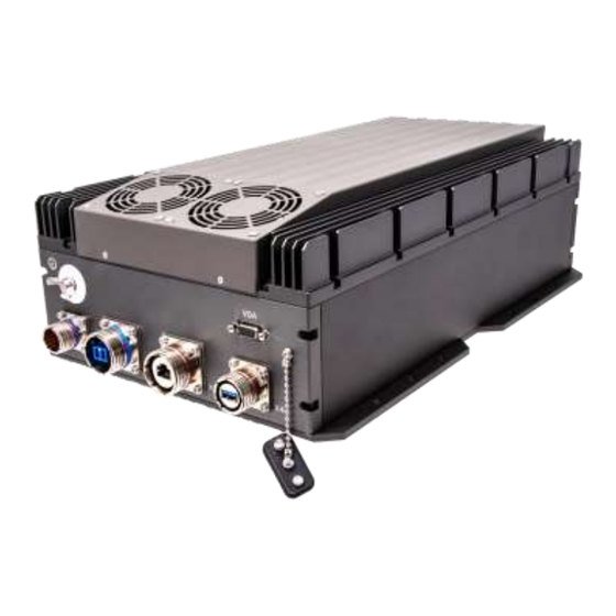
- Page 7 • Panel Component DC In label (X1) 10G LAN, label (X2) 1G LAN, label (X3) USB 3.0, label (X4) Isolated ground Plug Dedicated LED Power Button AES Hardware Easer Button 2.5” HDD/SSD Easy Swap Tray Remove COMS Battery...
- Page 8 Chapter 2: Jumpers and Connectors Locations D38999 Connector Pin Definitions X1 DC IN D38999(A1) Pin define A2 Y pin D38999(B1) V+(Y) V+(Y) V+(Y) V-(B) V-(B) DC IN V-(B) Ground Weave Ground ring Weave ring Amphenol TV07RW- 13-04P (DC IN) Amphenol TV06RW-13-04S (DC IN)
- Page 9 BIOS Setup This chapter describes the AMIBIOS™ Setup utility for the motherboard. The BIOS is stored on a chip and can be easily upgraded using a flash program. Note: Due to periodic changes to the BIOS, some settings may have been added or deleted and might not yet be recorded in this manual.
- Page 10 Note: The time is in the 24-hour format. For example, 5:30 P.M. appears as 17:30:00. The date's default value is the BIOS build date after RTC reset. SR800-D21A20 BIOS Version This feature displays the version of the BIOS ROM used in the system.
- Page 11 Warning: Take caution when changing the Advanced settings. An incorrect value, a very high DRAM frequency or an incorrect BIOS timing setting may cause the system to malfunction. When this occurs, restore to default manufacturer settings.
- Page 12 Boot Feature Quiet Boot Use this feature to select the screen display between POST messages or the OEM logo at bootup. Select Disabled to display the POST messages. Select Enabled to display the OEM logo instead of the normal POST messages. The options are Disabled and Enabled. Option ROM Messages Use this feature to set the display mode for the Option ROM.
- Page 13 • Microcode Revision • L1 Cache RAM • L2 Cache RAM • L3 Cache RAM • Processor 0 Version Hyper-Threading (ALL) Select Enabled to support Intel Hyper-threading Technology to enhance CPU performance. The options are Disable and Enable. Cores Enabled Set a numeric value to enable the number of cores.
- Page 14 Config TDP Use this feature to configure the Thermal Design Power (TDP) level. The options are Nominal, Level 1, and Level 2. EIST PSD Function This feature allows the user to choose between Hardware and Software to control the processor's frequency and performance (P- state).
- Page 15 Warning: Setting the wrong values in the sections below may cause the system to malfunction. North Bridge Configuration Memory Configuration Enforce POR Select POR (Plan of Record) to enforce POR restrictions on DDR4 frequency and volt- age programming. The options are POR and Disable.
- Page 16 SDDC Single device data correction +1 (SDDC Plus One) organizes data in a single bundle (x4/x8 DRAM). If any or all the bits become corrupted, corrections occur. The x4 con- dition is corrected on all cases. The x8 condition is corrected only if the system is in Lockstep Mode.
- Page 17 PCI-E Port Link Speed This feature shows the status of the device plugged into this slot. PCI-E Port Max Payload Size Use this feature to select the maximum payload size for this port. The options are 128B, 256B, and Auto. ...
- Page 18 Use this feature to enable Interrupt Remapping support, which detects and controls external interrupt requests. The options are Enable and Disable. Passthrough DMA Use this feature to allow devices such as network cards to access the system memory without using a processor. Select Enable to use the Non-Isoch VT_D Engine Pass Through Direct Memory Access (DMA) support.
- Page 19 ownership change should be claimed by the XHCI driver. The settings are Enabled and Disabled. Port 60/64 Emulation Select Enabled for I/O port 60h/64h emulation support, which in turn, will provide complete legacy USB keyboard support for the operating systems that do not support legacy USB devices. The options are Disabled and Enabled. ...
- Page 20 Port 0~7 Hot Plug Set this feature to Enable for hot plug support, which will allow the user to replace a SATA drive without shutting down the system. The options are Disable and Enable. Port 0~7 Spin Up Device On an edge detect from 0 to 1, set this feature to allow the PCH to initialize the device. The options are Disable and Enable. Port 0~7 SATA Device Type Use this feature to specify if the SATA port specified by the user should be connected to a Solid-State drive or a Hard Disk Drive.
- Page 21 The following information will display: • PCI Bus Driver Version • PCI Devices Common Settings: Above 4G Decoding (Available if the system supports 64-bit PCI decoding) Select Enabled to decode a PCI device that supports 64-bit in the space above 4G Address. The options are Disabled and Enabled.
- Page 22 BIOS > Advanced > PCIe/PCI/PnP Configuration > JMD2:M.2-H PCI-E 3.0 X2 lane 1 Type > USB3.0. Notes 2: SATA devices can be supported regardless of the BIOS setting (USB3.0 or PCIE). CPU SLOT6 PCI-E 3.0 X16 OPROM Use this feature to select which option for the add-on card in this slot. The options are Disabled, Legacy, and EFI. CPU SLOT7 PCI-E 3.0 X8 OPROM Use this feature to select which option for the add-on card in this slot.
- Page 23 Use this option to specify the wait time to press the ESC key to abort the PXE boot. Press "+" or "-" on your keyboard to change the value. The default setting is 0. Media Detect Count Use this option to specify the number of times media will be checked. Press "+" or "-" on your keyboard to change the value. The default setting is 1.
- Page 24 Character set. Select VT100+ to add color and function key support. Select ANSI to use the Extended ASCII Character Set. Select VT-UTF8 to use UTF8 encoding to map Unicode characters into one or more bytes. The options are VT100, VT100+, VT-UTF8, and ANSI.
- Page 25 Terminal Type Use this feature to select the target terminal emulation type for Console Redirection. Select VT100 to use the ASCII Character set. Select VT100+ to add color and function key support. Select ANSI to use the Extended ASCII Character Set. Select VT-UTF8 to use UTF8 encoding to map Unicode characters into one or more bytes.
- Page 26 Band Serial Port management. EMS (Emergency Management Services) Console Redirection Select Enabled to use a COM port selected by the user for EMS Console Redirection. The options are Disabled and Enabled. *If the feature above is set to Enabled, the following features are available for configuration: ...
- Page 27 *The features in the Trusted Computing section on this page are displayed if a TPM 1.2 module is detected: Configuration Security Device Support If this feature and the TPM jumper on the motherboard are both set to Enabled, onboard security devices will be enabled for TPM support to enhance data integrity and network security.
- Page 28 configuration: SHA256 PCR Bank Use this feature to disable or enable the SHA256 Platform Configuration Register (PCR) bank for the installed TPM device. The options are Disabled and Enabled. Pending Operation Use this feature to schedule a TPM-related operation to be performed by a security device for system data integrity. Your system will reboot to carry out a pending TPM operation.
- Page 29 5. Event Logs Use this menu to configure event log settings. Change SMBIOS Event Log Settings Enabling/Disabling Options SMBIOS Event Change this feature to enable or disable all features of the SMBIOS Event Logging during system boot. The options are Enabled and Disabled.
- Page 30 This feature is used to determine how long (in minutes) should the multiple event counter wait before generating a new event log. Enter a number between 0 to 99. The default setting is 60. Note: Reboot the system for the changes to take effect. ...
- Page 31 BMC network configuration Configure IPV4 support IPMI LAN Selection This feature displays the IPMI LAN setting. The default setting is Failover. IPMI Network Link Status This feature displays the IPMI Network Link status. The default setting is Dedicated LAN. Update IPMI LAN Configuration Select Yes for the BIOS to implement all IP/MAC address changes at the next system boot.
- Page 32 Station IPV6 Address Use this feature to enter the IPV6 address. Prefix Length Use this feature to change the prefix length. IPV6 Router1 IP Address Use this feature to change the IPV6 Router1 IP address. IPMI Extended Instruction The options of this feature are Enabled and Disabled. When this feature is Disabled, the system powers on quickly by removing BIOS support for IPMI extended instruction features.
- Page 33 Secure Boot Mode This feature allows the user to select the desired secure boot mode for the system. The options are Standard and Custom. *If Secure Boot Mode is set to Customized, Key Management features are available for configuration: CSM Support This feature is for manufacturing debugging purposes.
- Page 34 Export Select Yes to export a KEK from a file on an external media. Update Select Yes to load a factory default KEK or No to load from a file on an external media. Append Select Yes to add the KEK from the manufacturer's defaults list to the existing KEK. Select No to load the KEK from a file.
- Page 35 OsRecovery Signatures Details Select this feature to view the details of the dbr. Export Select Yes to export a dbr from a file on an external media. Update Select Yes to load a factory default dbr or No to load from a file on an external media. Append Select Yes to add the dbr from the manufacturer's defaults list to the existing dbr.
- Page 36 • Boot Option #4 • Boot Option #5 • Boot Option #6 • Boot Option #7 • Boot Option #8 • Boot Option #9 • Boot Option #10 • Boot Option #11 • Boot Option #12 • Boot Option #13 •...
- Page 37 Save Options Discard Changes and Exit Select this option to quit the BIOS Setup without making any permanent changes to the system configuration and reboot the computer. Select Discard Changes and Exit from the Exit menu and press <Enter>. Save Changes and Reset When you have completed the system configuration changes, select this option to save all changes made and reset the system.
- Page 38 Appendix A BIOS Codes BIOS Error POST (Beep) Codes During the POST (Power-On Self-Test) routines, which are performed upon each system boot, errors may occur. Non-fatal errors are those which, in most cases, allow the system to continue to boot. These error messages normally appear on the screen.
Need help?
Do you have a question about the SR800-D21A20 and is the answer not in the manual?
Questions and answers