
Related Manuals for Star Lake SR10B


Summary of Contents for Star Lake SR10B
- Page 1 SR10B MIL-STD Rugged Computer User’s Manual User’s Manual Revision Date: Oct. 07. 2016...
-
Page 2: Safety Information
SR10B User’s Manual Revision Date: Oct. 07. 2016 Safety Information Electrical safety To prevent electrical shock hazard, disconnect the power cable from the electrical outlet before relocating the system. When adding or removing devices to or from the system, ensure that the power cables for the devices are unplugged before the signal cables are connected. -
Page 3: Revision History
Initial Release Version 1.1 2016/10/7 New vibration isolation design Add WatchDog Function Packing list □SR10B MIL-STD Rugged Computer □Vibration Isolation Base Accessories Kit □ Terminal block 4 PIN x 1pcs □ Screw Package □ CD (Driver + User’s Manual) Ordering Information... -
Page 4: Table Of Contents
SR10B User’s Manual Revision Date: Oct. 07. 2016 Table of contents Safety Information ............................. 1 Electrical safety .............................. 1 Operation safety ............................1 Statement ..............................1 Revision History..............................2 Packing list................................2 Accessories Kit ..............................2 Ordering Information ............................2 Chapter 1: Product Introduction ........................ - Page 5 SR10B User’s Manual Revision Date: Oct. 07. 2016 4.4.4 SATA Configuration.......................... 28 4.4.5 Intel Rapid Start Technology......................33 4.4.6 PCH-FW Configuration ........................34 4.4.7 Intel Anti-Theft Technology Configuration ..................35 4.4.8 AMT Configuration .......................... 36 4.4.9 USB Configuration ........................... 38 4.4.10 IT8786 Super IO Configuration ......................
-
Page 6: Chapter 1: Product Introduction
SR10B User’s Manual Revision Date: Oct. 07. 2016 Chapter 1: Product Introduction 1-1 Key Features System Intel® Core™ i7 Haswell , BGA type Core i7-4700EQ (4C x 2.4/1.7 GHz), 6M Cache (47W) Chipset Intel® QM87 PCH Ethernet Chipset Intel® I210-IT & I217-LM GbE... - Page 7 SR10B User’s Manual Revision Date: Oct. 07. 2016 Relative Humidity 5% to 95%, non-condensing Serial Interface & Signals Serial Standards 1x RS-232/422/485 port, Jumper-selectable (DB9 male) RS-232 TxD, RxD, DTR, DSR, RTS, CTS, DCD, GND RS-422 TxD+, TxD-, RxD+, RxD-, GND...
-
Page 8: Front Panel Components
SR10B User’s Manual Revision Date: Oct. 07. 2016 1.2 Front Panel Components 2 x USB 3.0 (Type A) LED Indicators 2 x DB9 (2 x RS232) Power Button Power Input (9~36V DC in) Swappable 2.5” HDD Tray... -
Page 9: Back Panel Components
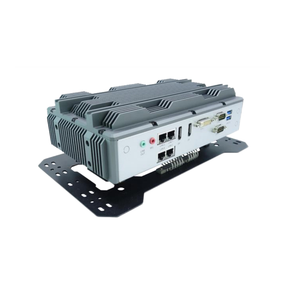
SR10B User’s Manual Revision Date: Oct. 07. 2016 1.3 Back Panel Components Audio Jack (1 x MIC, 1 x Line Out) 4 x RJ45 LAN Ports 2 x DisplayPort 1 x DVI-I 2 x DB ( 1 x RS232/422/485 with 5V/12V selectable, 1 x RS232) -
Page 10: Mechanical Dimensions
SR10B User’s Manual Revision Date: Oct. 07. 2016 1.4 Mechanical Dimensions... -
Page 11: Chapter 2: Jumpers And Connectors
SR10B User’s Manual Revision Date: Oct. 07. 2016 Chapter 2: Jumpers and Connectors This chapter describes the jumpers and connectors on the systems’ motherboard. 2.1 Front Panel Connector Pin Definitions... - Page 12 SR10B User’s Manual Revision Date: Oct. 07. 2016...
- Page 13 SR10B User’s Manual Revision Date: Oct. 07. 2016...
-
Page 14: Internal Connector And Jumper Setting
SR10B User’s Manual Revision Date: Oct. 07. 2016 2.3 Internal Connector and Jumper Setting... -
Page 15: Chapter 3: Installation
SR10B User’s Manual Revision Date: Oct. 07. 2016 Chapter 3: Installation This chapter provide users the steps to install the HDD tray and vibration isolation base 3.1 HDD tray • Loosen the screws and pull out the 2.5” HDD tray. -
Page 16: Vibration Isolation Base
SR10B User’s Manual Revision Date: Oct. 07. 2016 3.3 Vibration Isolation Base • Let the computer be upside down. • Locate the vibration isolation base on the computer by the screw holes. • Pick 6 screws from the screw package. -
Page 17: Chapter 4: Ami Bios Utility
SR10B User’s Manual Revision Date: Oct. 07. 2016 Chapter 4: AMI BIOS UTILITY This chapter provides users with detailed descriptions on how to set up a basic system configuration through the AMI BIOS setup utility. 4.1 Starting To enter the setup screens, perform the following steps: •... -
Page 18: Main Menu
SR10B User’s Manual Revision Date: Oct. 07. 2016 4.3 Main Menu The Main menu is the screen that first displays when BIOS Setup is entered, unless an error has occurred. -
Page 19: Advanced Menu
SR10B User’s Manual Revision Date: Oct. 07. 2016 You could setup these items on the Main menu: System Language: Choose the system default language. System Date: Set the date. Use Tab to switch between date elements. System Time: Set the time. Use Tab to switch between time elements. -
Page 20: Pci Subsystem Settings
SR10B User’s Manual Revision Date: Oct. 07. 2016 4.4.1 PCI Subsystem Settings PCI, PCI-X and PCI Express settings. PCI Common Settings PCI Latency Timer: Value to be programed into PCI Latency Timer Register. VGA Palette Snoop: Enable or disable VGA Palette Registers Snooping. - Page 21 SR10B User’s Manual Revision Date: Oct. 07. 2016 BIOS to select value. PCI Express Link Register Settings ASPM Support: Set the ASPM level: Force L0s - Force all links to L0s state: AUTO - BIOS auto configure: DISABLE- Disables ASPM. WARNING: Enabling ASPM may cause some PCI-E devices to fail.
-
Page 22: Acpi Settings
SR10B User’s Manual Revision Date: Oct. 07. 2016 4.4.2 ACPI Settings System ACPI Parameters. Enable ACPI Auto Configuration Enable/disable BIOS ACPI Auto Configuration. Enable Hibernation Enables or Disables system ability to hibernate (OS/S4 sleep state). This option may be not effective with some OS. -
Page 23: Cpu Configuration
SR10B User’s Manual Revision Date: Oct. 07. 2016 4.4.3 CPU configuration CPU Configuration Parameters. - Page 24 SR10B User’s Manual Revision Date: Oct. 07. 2016...
- Page 25 SR10B User’s Manual Revision Date: Oct. 07. 2016 Hyper-threading Enable for windows XP and Linux(OS optimized for Hyper-Threading Technology) and Disabled for other OS(OS not optimized for Hyper-Threading Technology). When Disabled only one thread per enabled core is enabled. Active Processor Cores Number of cores to enable in each processor package.
- Page 26 SR10B User’s Manual Revision Date: Oct. 07. 2016 Energy performance Optimize between performance and power savings. Package power limit lock: When enabled PACKAGE_POWER_LIMIT MSR will be locked and a reset will be required to unlock the register. CPU Power limit1: CPU power limit1 value...
- Page 27 SR10B User’s Manual Revision Date: Oct. 07. 2016 auto-demote information. Package C state demotion: enable package C state demotion C1 state auto undemotion: undemotion from demoted C1. C3 state auto undemotion: undemotion from demoted C1. Package C state undemotion: enable package C state undemotion C state Pre-wake: Enable or disable C state Pre-Wake feature.
- Page 28 SR10B User’s Manual Revision Date: Oct. 07. 2016 Debug interface lock Lock CPU debug interface setting. IOUT OFFSET Sign 0 positive offset. 1 negative offset. IOUT OFFSET VR IOUT OFFSET configuration 0~625. IOUT SLOPE VR IOUT SLOPE configuration range 0~1023.
-
Page 29: Sata Configuration
SR10B User’s Manual Revision Date: Oct. 07. 2016 4.4.4 SATA Configuration This section is used to configure the SATA drives. - Page 30 SR10B User’s Manual Revision Date: Oct. 07. 2016 SATA Controller(s) Enable or disable SATA device. SATA Mode Selection Determines how SATA controller(s) operate. The options are: IDE, AHCI, RAID SATA Test Selection Enable or disable Test Mode Aggressive LPM Support Enable PCH to aggressively enter link power state.
- Page 31 SR10B User’s Manual Revision Date: Oct. 07. 2016 Software Feature Mask Configuration RADI OROM/RST driver will refer to the SWFW configuration to enable or disable the storage features. RAID0: Enable or disable RAID0 feature. RAID1: Enable or disable RAID1 feature.
- Page 32 SR10B User’s Manual Revision Date: Oct. 07. 2016 Spin Up Device: On an edge detec from 0 to 1, the PCH starts a COMRESET initialization sequence to the device. Serial ATA Port 2 Port 2: Enable or disable SATA port Hot Plug: Designates this port as Hot Pluggable.
- Page 33 SR10B User’s Manual Revision Date: Oct. 07. 2016 SATA device type: Identify the SATA port is connected to Solid State Drive or Hard Disk Drive. Spin Up Device: On an edge detec from 0 to 1, the PCH starts a COMRESET initialization sequence to the device.
-
Page 34: Intel Rapid Start Technology
SR10B User’s Manual Revision Date: Oct. 07. 2016 4.4.5 Intel Rapid Start Technology Enable or disable Intel Rapid Start Technology... -
Page 35: Pch-Fw Configuration
SR10B User’s Manual Revision Date: Oct. 07. 2016 4.4.6 PCH-FW Configuration Configure Management Engine Technology Parameters. MDES BIOS Status Code Enable/Disable MDES BIOS Status Code. Firmware Update Configuration Configure Management Engine Technology Parameters. Me FW Image Re-Flash: Enable/Disable Me FW Image Re-Flash function. -
Page 36: Intel Anti-Theft Technology Configuration
SR10B User’s Manual Revision Date: Oct. 07. 2016 4.4.7 Intel Anti-Theft Technology Configuration Disabling Intel AT allow user to login to platform. This is strictly for testing only. This does not disable Intel AT services in ME. Intel Anti-Theft Technology Enable/Disable Intel AT in BIOS for testing. -
Page 37: Amt Configuration
SR10B User’s Manual Revision Date: Oct. 07. 2016 4.4.8 AMT Configuration Configure Active Management Technology Parameters. Intel AMT Enable/Disable Intel Active Management Technology BIOS Extension. Note: iAMT H/W is always enabled. This option just controls the BIOS extension execution. If enabled, this requires additional firmware in the SPI device. - Page 38 SR10B User’s Manual Revision Date: Oct. 07. 2016 Un-Configure ME OEMFlag Bit 15: Un-Configure ME without password. Amt Wait Timer Set Timer to wait before sending ASF_GET_BOOT_OPTIONS. Disable ME Set ME to Soft Temporary Disabled. Enable/Disable Alert Specification Format. Activate Remote Assistance Process Trigger CIRA boot.
-
Page 39: Usb Configuration
SR10B User’s Manual Revision Date: Oct. 07. 2016 4.4.9 USB Configuration USB Configuration Parameters. Legacy USB Support Enables legacy USB support. AUTO option disables legacy support if no USB devices are connected. DISABLE option will keep USB devices available only for EFI applications. -
Page 40: It8786 Super Io Configuration
SR10B User’s Manual Revision Date: Oct. 07. 2016 USB hardware delays and time-outs: USB transfer time-out: The time-out value for Control, Bulk, and Interrupt transfers. The options are 1 sec, 5 sec, 10 sec, 20 sec. Device reset time-out: USB mass storage device Start Unit command time-out. The options are 10 sec,20 sec, 30 sec, 40 sec. - Page 41 SR10B User’s Manual Revision Date: Oct. 07. 2016 Serial Port 1 Configuration Set Parameters of Serial Port 0 (COMA). Serial Port: Enable or Disable Serial Port (COM). Device Settings: IO=3F8h, IRQ=4 Change Settings: Select an optimal setting for Super IO device.
-
Page 42: It8786 Hw Monitor
SR10B User’s Manual Revision Date: Oct. 07. 2016 4.4.11 IT8786 HW Monitor Monitor hardware status. -
Page 43: Serial Port Console Redirection
SR10B User’s Manual Revision Date: Oct. 07. 2016 4.4.12 Serial Port Console Redirection Console Redirection Console Redirection Enable or Disable. Console Redirection Setting The Settings specify how the host computer and the remote computer will exchange data. Both computers should have the same or compatible setting. -
Page 44: Network Stack
SR10B User’s Manual Revision Date: Oct. 07. 2016 the receiving buffers are full, a “stop” signal can be sent to stop the data flow. Once the buffers are empty,a “star” signal can be sent to re-start the flow. Hardware flow control uses two wires to sendstart/stop signals. - Page 45 SR10B User’s Manual Revision Date: Oct. 07. 2016 4.4.14 Intel I210-IT Gigabit Network Connection Configure Gigabit Ethernet device parameters. PORT CONFIGURATION MENU NIC Configuration: Configure Boot Protocol, wake on LAN, Link Speed, and VLAN. Blink LEDs: Identify the physical network port by blinking the associated LED.
-
Page 46: Chipset
SR10B User’s Manual Revision Date: Oct. 07. 2016 4.5 Chipset This section gives you functions to configure the system based on the specific features of the chipset. The chipset manages bus speeds and access to system memory resources. -
Page 47: Pch Io Configuration
SR10B User’s Manual Revision Date: Oct. 07. 2016 4.5.1 PCH IO configuration PCI Express Configuration PCI Express Configuration settings PCIE Root Port Function Swapping: Enable or disable PCI Express PCI Express Root Port Function Swapping. Subtractive Decode: Enable or disable PCI Express Subtractive Decode. - Page 48 SR10B User’s Manual Revision Date: Oct. 07. 2016 SENFE: Enable or disable Root PCI Express System Error on Non-Fatal Error. SECE: Enable or disable Root PCI Express System Error on Correctable Error. PME SCI: Enable or disable PCI Express PME SCI.
- Page 49 SR10B User’s Manual Revision Date: Oct. 07. 2016 Reseved Memory: Reserved Memory Range for this Root Bridge. Prefetchable Memory: Prefetchable Memory Range for this Root Bridge. Reserved I/O: Reserved I/O (4K/8K/12K/16K/…/48K) Range for this Root Bridge. PCIE LTR: PCIE Latency Reporting Enable/Disable.
- Page 50 SR10B User’s Manual Revision Date: Oct. 07. 2016 more time at POST time. Extra Bus Reserved: Extra Bus Reserved (0-7) for bridges behind this Root Bridge. Reseved Memory: Reserved Memory Range for this Root Bridge. Prefetchable Memory: Prefetchable Memory Range for this Root Bridge.
- Page 51 SR10B User’s Manual Revision Date: Oct. 07. 2016 Hot Plug: Enable or disable PCI Express Hot Plug. PCIe Speed: Select PCI Express port speed. Detect Non-Compliance Device: Detect Non-Compliance PCI Express Device. If enable, it will take more time at POST time.Extra Bus Reserved: Extra Bus Reserved (0-7) for bridges behind this Root Bridge.
- Page 52 SR10B User’s Manual Revision Date: Oct. 07. 2016 SECE: Enable or disable Root PCI Express System Error on Correctable Error. PME SCI: Enable or disable PCI Express PME SCI. Hot Plug: Enable or disable PCI Express Hot Plug. PCIe Speed: Select PCI Express port speed.
- Page 53 SR10B User’s Manual Revision Date: Oct. 07. 2016 SEFE: Enable or disable Root PCI Express System Error on Fatal Error. SENFE: Enable or disable Root PCI Express System Error on Non-Fatal Error. SECE: Enable or disable Root PCI Express System Error on Correctable Error.
- Page 54 SR10B User’s Manual Revision Date: Oct. 07. 2016 CER: Enable or disable PCI Express Device Correctable Error Reporting. CTO: Enable or disable PCI Express Completion Timer TO. SEFE: Enable or disable Root PCI Express System Error on Fatal Error. SENFE: Enable or disable Root PCI Express System Error on Non-Fatal Error.
- Page 55 SR10B User’s Manual Revision Date: Oct. 07. 2016 Disabled=Azalia will be unconditionally disabled. Enabled=Azalia will be unconditionally Enabled. Auto=Azalia will be enabled if present, disabled otherwise. Azalia Docking Support: Enable or disable Azalia Docking Support of Audio Controller. Azalia PME: Enable or disable Power Management capability of Audio Controller.
- Page 56 SR10B User’s Manual Revision Date: Oct. 07. 2016 Watch Dog Function select...
-
Page 57: System Agent Sa
SR10B User’s Manual Revision Date: Oct. 07. 2016 4.5.2 System AGENT SA VT-d Check to enable VT-d function on MCH. Graphics Configuration Graphics Turbo IMON Current: Graphics turbo IMON current values supported (14-31). Primary Display: select which of AUTO/IGFX/PEG/SG graphics device should be primary display or select SG for switchable GFX Primary PEG: Select Auto/PEG1/PEG2 Graphics device should be Primary PEG. - Page 58 SR10B User’s Manual Revision Date: Oct. 07. 2016 Primary IGFX Boot Display: Select the Video Device which will be activated during POST. This has no effect if external graphics present. Secondary boot display selection will appear based on your selection. VGA modes will be supported only on primary display.
-
Page 59: Boot
SR10B User’s Manual Revision Date: Oct. 07. 2016 4.6 Boot This section is used to configure the boot features. Setup Prompt Timeout Number of seconds to wait for setup activation key. 65535(0xFFFF) means indefinite waiting. Bootup NumLock State Select the keyboard NumLock state. -
Page 60: Security
SR10B User’s Manual Revision Date: Oct. 07. 2016 disabling GA20; this option is useful when any RT code is executed above 1MB. Option ROM Messages: Set display mode for option ROM. INT19 Trap Response: BIOS reaction on INT19 trapping by option ROM: IMMEDIATE-execute the trap right away;... -
Page 61: Save And Exit
SR10B User’s Manual Revision Date: Oct. 07. 2016 4.8 Save and Exit This screen provides functions for handling changes made to the BIOS settings and the exiting of the Setup program. Save Changes and Exit Exit system setup after saving the changes. - Page 62 SR10B User’s Manual Revision Date: Oct. 07. 2016 Restore the User Defaults to all the setup options. Launch EFI Shell from filesystem device Attempts to launch EFI Shell application (Shellx64.efi) from one of the available filesystem devices.
Need help?
Do you have a question about the SR10B and is the answer not in the manual?
Questions and answers