
Related Manuals for Flintec FT-10Fill Series


Summary of Contents for Flintec FT-10Fill Series
- Page 1 FT-10Fill Filling Controller Technical Manual Flintec GmbH Bemannsbruch 9 74909 Meckesheim GERMANY www.flintec.com...
-
Page 2: Table Of Contents
Table Of Contents: Safety Instructions ..............5 Declaration Of Conformity ............6 Non-automatic Weighing Instrument (NAWI) ............... 6 Introduction ................7 Overview ......................... 7 Key features ......................7 Specifications ......................8 The Front View and Key Functions ............... 12 3.4.1 Display ........................ - Page 3 Mode 1: Open Container Filling as Gross ............. 42 Mode 2: Open Container Filling as Net ..............45 Mode 3: Bung-Type Container Filling as Gross............. 48 Mode 4: Bung-Type Container Filling as Net ............52 Mode 5: Packing / Bagging ................... 56 Mode 6: Multicycle Packing / Bagging ..............
- Page 4 CC-Link (only FT-10 FILL CC) ..........112 17.1 Data Format ......................112 17.2 CC-Link Configuration ..................113 17.3 CC-Link Data Structure ..................113 Powerlink (only FT-10Fill PL ) ..........114 18.1 Data Format ......................115 18.2 XDD Configuration ....................115 18.3 Powerlink Data Structure ..................
- Page 5 FLINTEC operating and maintenance instructions. FLINTEC shall not be liable against any damages or problems arising from the use of any options or any consumable products other than those designated as Original FLINTEC Products.
-
Page 6: Safety Instructions
OPERATE, CLEAN, INSPECT, MAINTAIN, SERVICE, OR TAMPER WITH THIS EQUIPMENT. ALWAYS DISCONNECT THIS EQUIPMENT FROM THE POWER SOURCE BEFORE CLEANING OR PERFORMING MAINTENANCE. CALL FLINTEC ENGINEERING FOR PARTS, INFORMATION, AND SERVICE. WARNING! ONLY PERMIT QUALIFIED PERSONNEL TO SERVICE THIS EQUIPMENT. -
Page 7: Declaration Of Conformity
2. D ECLARATION ONFORMITY EU-Konformitätserklärung EU-Declaration of Conformity Monat/Jahr: month/year: 04/2016 Hersteller: Manufacturer: Flintec GmbH Anschrift: Address: Bemannsbruch 9 D-74909 Meckesheim Deutschland Produktbezeichnung: Product name: FT-10 Fill and FT-10 Flow (Wäge Indikator / Weighing Indicator): Nr. der Bauartzulassung: FT-10 Fill and FT-10 Flow No oft the EC type-examination certificate: DK 0199.492, Delta... -
Page 8: Introduction
3. I NTRODUCTION 3.1 Overview FT-10 FILL filling controller is used for processing various type filling applications. It has 4 standard filling modes for open container filling and above level bung hole filling and 2 modes for packing machines. The controller has 4 opto-isolated digital input and 5 relay contact outputs. -
Page 9: Specifications
3.3 Specifications Common Specifications A/D Converter: A/D converter type: 24 bit Delta-Sigma ratiometric with integral analog and digital filters Conversion rate: Up to 1600 measurement values per second 0.4 μV/d (Approved); 0.1 μV/d (Non approved) Input sensitivity: -18 mV … +18 mV Analog input range: Internal resolution: up to 16 000 000... - Page 10 DC Power supply: 12 to 28 VDC (max. 300 mA) Environment and Enclosure: -10°C … +40°C; 85% RH max, non-condensing, Operation temperature -15°C … +55°C non approved, non OIML Panel type, front panel and rear panel are stainless steel; Enclosure Aluminum body.
- Page 11 FT-10 FILL CO CANopen Communication: 10 kbit/s – 1 Mbit/s (selectable) kbit/s Data rate: ESD file Generic EDS-file provided Line with Trunkline, Dropline structure and Termination at both Ends Topology: Line length depending on baud rate 25 – 500 meter. 2 wire shielded twisted pair cable Installation: Alternatively 4 wire with 24 Volt power over the bus...
- Page 12 FT-10 FILL PL Powerlink Communication Data rate 100 Mbit/s, half duplex Supports POWERLINK V2.0 Communication Profile Specification version Compatibility 1.2.0 XDD file XDD-file provided Ring redundancy Available Topology 100% free choice of star, tree, ring or daisy chain Switched Ethernet transmission with shielded twisted pair cables and RJ-45 Installation connectors.
-
Page 13: The Front View And Key Functions
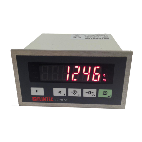
3.4 The Front View and Key Functions FT-10 Fill Figure 3.1 - Front panel view of FT-10 FILL 3.4.1 Display The weight display of FT-10 FILL is seven segments LED. At the right side of the display there are three LED’s for indicating the net, process steps and the unit (standard kg). -
Page 14: Key Lock
3.4.3 Key Lock FT-10 has ability to lock the keys to avoid unauthorized person’s interfere. You can activate or deactivate this function by long pressing < > key, press < > and < > keys sequentially. [Lock] prompt appears for a short while to indicate the pressed key is locked. 3.4.4 Housing FT-10 FILL housings are panel type with stainless steel front and back parts and aluminium body. - Page 15 FT-10 FILL EN Panel type rear view FT-10 FILL CO Panel type rear view FT-10 FILL EI rear view FT-10 FILL EC rear view FT-10 FILL CC type rear view FT-10 FILL PL type rear view FT-10 Fill Technical Manual, Rev. 2.21, July 2020 Page 14 of 131...
-
Page 16: Installation
4. I NSTALLATION PRECAUTION Please read this section carefully before installation of the instrument. Applying the recommendations in this section will increase your system reliability and long-term performance. 4.1 Recommendations 4.1.1 Control Cabinet Design Warning Please care the following warnings for designing the control cabinet which will increase your system reliability. -
Page 17: Power Supply Connection And Grounding
4.3.1 Power Supply Connection and Grounding Power supply voltage of the instrument shall be between 12 V DC and 28 V DC. The pin configuration of the 24 V DC power supply connector located right - bottom of the instrument is shown in Figure 4.1 below. The pin layout of the 24 V DC connector of FT-10 FILL Series... -
Page 18: Rs 232C Connection
4.3.3 RS 232C Connection RS 232C port usage and specifications are shown in the table below and on Page 29. Interfacing with PC or PLC, remote display connection, programming via Usage IndFace1X Continuous, Fast Continuous, Printer Format, BSI Protocol, Data formats Modbus-RTU High-Low, Modbus-RTU Low-High Baud rate 1200 / 2400 / 4800 / 9600 (Default) / 19200 / 38400 / 57600 / 115200 bps... -
Page 19: Profibus Connection (Only Ft-10 Fill Pb)
Warning: Disconnect IndFace1X PC software before starting Modbus-RTU interfacing. 4.3.5 Profibus Connection (only FT-10 FILL PB) Profibus connection is done as indicated below in Figure 4.5. Figure 4.5 - FT-10 FILL PB serial interface connections PROFIBUS Connector pin configuration (DB9F) Signal Description B Line... -
Page 20: Ethernet Connection (Only Ft-10 Fill En)
The HUB connection cabling will be a direct connection as shown below: Figure 4.7 - HUB connection The PC connection cabling will be done via cross cable as shown below. IP address blocks and gateway address of FT-10 FILL and PC should be the same in cross connection. Figure 4.8 - Cross PC connection Warning Connect the shield to the reference ground or shield pin of the power connector. -
Page 21: Canopen Connection (Only Ft-10 Fill Co)
The PC connection cabling will be done via cross cable as shown below. IP address blocks and gateway address of FT-10 FILL and PC should be the same in cross connection. Figure 4.10 - Cross PC connection Warning Connect the shield to the reference ground or shield pin of the power connector. Warning: Disconnect IndFace1X PC software before starting Modbus-RTU interfacing. -
Page 22: Ethernet/Ip Connection (Only Ft-10 Fill Ei)
4.3.9 EtherNet/IP Connection (only FT-10 FILL EI) EtherNet/IP connection is done as indicated below in Figure 4.13. Figure 4.13 – FT-10 FILL EI interface connections EtherNet/IP Connector pin configuration (RJ45) Signal Description Differential Ethernet transmit data + TX− Differential Ethernet transmit data − Differential Ethernet receive data + RX−... -
Page 23: Ethercat Connection (Only Ft-10 Fill Ec)
4.3.10 EtherCAT Connection (only FT-10 FILL EC) EtherCAT connection is done as indicated below in Figure 4.16. Figure 4.16 – FT-10FLOW EC interface connections EtherCAT Connector pin configuration (RJ45) Signal Description Differential Ethernet transmit data + TX− Differential Ethernet transmit data − Differential Ethernet receive data + RX−... -
Page 24: Cc-Link Connection (Only Ft-10 Fill Cc)
4.3.11 CC-Link Connection (only FT-10 FILL CC) CC-Link connection is done as indicated below in Figure 4.19. Figure 4.19 – FT-10 FILL CC interface connections CC-Link Connector pin configuration Signal Description PositiveRS485 Rxd/TxD NegativeRS485 Rxd/TxD Signal ground Cable Shield Protective Earth Warning: Connect the shield to the reference ground or shield pin of the power connector. -
Page 25: Powerlink Connection (Only Ft-10 Fill Pl )
4.3.12 Powerlink Connection (only FT-10 FILL PL ) Powerlink connection is done as indicated below in Figure 4.16. Figure 4.20 - BX13 PL interface connections Powerlink Connector pin configuration (RJ45) Signal Description Differential Ethernet transmit data + TX− Differential Ethernet transmit data − Differential Ethernet receive data + RX−... -
Page 26: Digital Inputs And Outputs Connection
4.3.13 Digital Inputs and Outputs Connection Inputs connection diagram is shown in Figure 4.22. Inputs 12…28 V DC, 10 mA Figure 4.22 - Inputs connection diagram Outputs connection diagram is shown in Figure 4.23. Outputs are 250 V AC or 30 V DC, 1 A. Figure 4.23 - Outputs connection diagram = 24 V –1.5 V), 100 mA. -
Page 27: Commissioning
4.4 Commissioning PRECAUTION Please read this manual carefully before energizing the instrument. Perform the commissioning operation according the procedure given in this section. Only trained person is allowed for cleaning, commissioning, checking and servicing of the instrument. The interference of untrained person may cause some unwanted damages or injuries. -
Page 28: Programming And Calibration
5. P ROGRAMMING AND ALIBRATION In this section you will find the programming and calibration procedure of FT-10 FILL indicator according to your application. The signs those take place on the lower right corner of the keys indicate the function of the keys in programming menu. -
Page 29: Fast Access To The Calibration
5.2 Fast Access to the Calibration The instrument has fast access calibration feature to earn time to the service technician. If only the calibration adjustment is needed, follow the steps below to access the calibration parameters fast. Display Operation [123.456 kg ] Press key until [ PASSWr ] prompts seen. -
Page 30: Programming
(Page 79) 6 : Fast continuous mode (Page 73) ( * ) Warning : Use for Flintec remote displays interfacing. CR and LF should be enabled. [001 3] Baud Rate 0 : 1200 Baud 2400 Baud 2 : 4800 Baud... - Page 31 (Page 79) 6 : Fast continuous mode (Page 73) ( * ) Warning : Use for Flintec remote displays interfacing. CR and LF should be enabled [011 3] Baud Rate 0 : 1200 Baud 2400 Baud 2 : 4800 Baud...
- Page 32 [03-] Ethernet (Only FT-10 FILL EN) This sub-block includes the parameters related with the Ethernet of FT-10 FILL controller. [030 5 ] Data Format 0 : No data transfer. 1 : Continuous data output (Page 72) 2 : Print mode (Parameter [040] (Page 32) 3 : BSI command set...
- Page 33 [04-] Printer If one of the serial interfaces is selected as printer, the label settings will be made in his sub-block. [040 2 ] Print Out Format 1 : Single line (Page 73) 2 : Multi line-24 (Page 73) 3 : Multi line-16 (Page 73) [041 1] CN (Consecutive Number) 0 : The “Consecutive Number”...
- Page 34 [05-] Profibus (Only FT-10 FILL PB) This sub-block includes the parameters related with the Profibus interfaces of FT-10 FILL controller. [050 0 ] Data Format 0 : Signed 32 bit integer, no decimal point implied 1 : 32 bit float, decimal point implied [051 000] Rack Address The Profibus rack address of FT-10 FILL will be entered via keypad between 001 to 126.
-
Page 35: Configuration Block [1--]
5.4.2 Configuration Block [1--] In this block the parameters take place which are being used to set FT-10 FILL according to your application. [116 3] Function key This key function is programmed as; 0 : No any 1 : Total 2 : 1/hour (ton/hour or klb/hour) indication 3 : Quantity 4 : Last filling value... -
Page 36: Scale Block [2--]
5.4.3 Scale Block [2--] [20-] Set Up The parameters about weighing operation are being entered here. [200 0] Approved ( * ) 0 : No 1 : OIML 2 : Hopper and Tank ( * ) Warning: Taring, Zero Tracking etc. functions disabled. [201 0] Increased Indication 0 : by pressing key... -
Page 37: Calibration Block [3--]
A minimum of 20% of scale capacity is necessary for calibration; FLINTEC recommends 50 to 100%. A calibration error will result if insufficient weight is used. 5. Place the test weights or another practical weight on the scale. - Page 38 If the value of the test weights that will be used is different from the value shown on the display, type the new value via tare and zero keys. A minimum of 20% of scale capacity is necessary for calibration; Flintec recommends 50 to 100%. A calibration error will result if insufficient weight is used.
- Page 39 [313 ] eCal Calibration Warning The scale capacity and resolution (parameter [212]) shall be entered before performing eCal. This parameter is being used to perform calibration without using any test weights. FT-10 FILL A/D coefficients are adjusted in production for increasing eCal accuracy. The calibration coefficients are calculated by scale capacity, total load cell capacity, load cell full scale output, and estimated dead load.
-
Page 40: Metrological Data Block [8--]
5.6 Metrological Data Block [8--] The parameters about Metrologic Registry are being entered in this section. [80-] Legal Metrologic Records [800] Counter This counter increases by 1 automatically after entering the programming mode with DIP switch. This counter cannot be changed manually. 5.7 Diagnostics [9--] The operations about checking and testing FT-10 FILL can be made here. - Page 41 [91-] Firmware Information [910 ] Version of Option Board [ XX.YY] The format of the version is XX.YY. XX digits are major version number and YY digits are minor version number for firmware changing. [92-] Log Book [920 ] Error history [ Err XX ] The last 20 errors listed in this parameter.
-
Page 42: Filling Modes
6. F ILLING ODES Mode Description Application Liquid or bulk filling into container Open container filling as Gross Bag, Big bag filling Open container filling as Net Automatic rotary filling machines Bung-Type container filling as Gross Above level liquid filling Bung-Type container filling as Net Automatic bagging machines Accurate filling and emptying... -
Page 43: Mode 1: Open Container Filling As Gross
6.1 Mode 1: Open Container Filling as Gross Typical Applications • Open container filling. • Filling into big bag. Operation • Filling starts with Start Input or automatically and is executed as 2 speeds directly into a container. • Process ends after removing the container from the platform. - Page 44 Mode Related Display Messages The messages below are shown on the display in the filling cycle or if there is any error in the filling. Display Operation [ StArt ] This message is shown on the display during Start Delay. This message is shown at the end of filling.
- Page 45 Digital Inputs and Outputs Connection I / O Descriptions Start of filling Input 1 Input 2 Input 3 Reset Input 4 Coarse feeding Output 1 Fine feeding Output 2 Output 3 End of filling Output 4 Output 5 Error at Zero range (refer to par. [117] Example of a connection diagram FT-10 Fill;...
-
Page 46: Mode 2: Open Container Filling As Net
6.2 Mode 2: Open Container Filling as Net Typical Application • Open container filling. • Filling in to big bag. Operation • Filling starts with Start Input or automatically and is executed as 2 speeds directly into a container. • Process ends after removing the container from the platform. - Page 47 Mode Related Display Messages The messages below are shown on the display in the filling cycle or if there is any error in the filling. Display Operation This message is shown on the display during Start Delay. [ StArt ] This message is shown at the end of filling.
- Page 48 Digital Inputs and Outputs Connection I / O Descriptions Start of filling Input 1 Input 2 Input 3 Reset Input 4 Coarse feeding Output 1 Fine feeding Output 2 Output 3 End of filling Output 4 Output 5 Error at Zero range (refer to par. [117]) Example of a connection diagram FT-10 Fill;...
-
Page 49: Mode 3: Bung-Type Container Filling As Gross
6.3 Mode 3: Bung-Type Container Filling as Gross Typical Application • Container which has bunghole filling in gross. • Tin, drum filling machines. Operation • After receiving start input or automatically, filling valve goes through hole of the container. • Filling starts and is executed as 2 speeds directly into a container as above surface. - Page 50 Note: For TARGET and TOLERANCE entry please see section 7, page 69 Mode Related Display Messages The messages below are shown on the display in the filling cycle or if there is any error in the filling. Display Operation [ StArt ] This message is shown on the display during Start Delay.
- Page 51 Filling cycle Press <Zero> key if the scale is not indicated zero after powered on. Apply start input after loading the scale with the container. The filling is done as indicated below. The [FuLL] prompt is displayed after end of the filling and take off the container.
- Page 52 Example of a connection diagram FT-10 Fill; FILLING CONTROLLER ( 1 ) Manual control circuitry is not indicated. ( 2 ) Very important : If Outputs are supplied DC, reverse diodes should always be installed. FT-10 Fill Technical Manual, Rev. 2.21, July 2020 Page 51 of 131...
-
Page 53: Mode 4: Bung-Type Container Filling As Net
6.4 Mode 4: Bung-Type Container Filling as Net Typical Applications • Container which has bunghole filling in net. • Tin, drum filling machines. Operation • After receiving start input or automatically, filling valve goes through hole of the container. • Filling starts is executed as 2 speeds directly into a container as above surface. - Page 54 Note: For TARGET and TOLERANCE entry please see section 7, page 69 Mode Related Display Messages The messages below are shown on the display in the filling cycle or if there is any error in the filling. Display Operation This message is shown on the display during Start Delay. [ StArt ] Means the filling valve is going down.
- Page 55 Filling cycle Press <Zero> key if the scale is not indicated zero after powered on. Apply start input after loading the scale with the container. The filling is done as indicated below. The [FuLL] prompt is displayed after end of the filling and take off the container.
- Page 56 Example of a connection diagram FT-10 Fill; FILLING CONTROLLER ( 1 ) Manual control circuitry is not indicated. ( 2 ) Very important : If Outputs are supplied DC, reverse diodes should always be installed. FT-10 Fill Technical Manual, Rev. 2.21, July 2020 Page 55 of 131...
-
Page 57: Mode 5: Packing / Bagging
6.5 Mode 5: Packing / Bagging Typical Applications • Packing and Bag filling machines. • Weighing of additives in tank or hopper. Operation • The container is filled up to target value accurately as 2 speeds. • It is emptied totally by applying emptying input. •... - Page 58 Mode Related Display Messages The messages below are shown on the display in the filling cycle or if there is any error in the filling. Display Operation It is displayed during automatic zeroing before feeding. [-Zero- ] It is displayed during gate position control. [GAtE ] This prompt is displayed at the end of Filling by toggling with the [FuLL ]...
- Page 59 drawing above. If this parameter is adjusted to 0, the fine feed output is activated after coarse feeding. Digital Inputs and Outputs Connection I / O Descriptions Start for filling Input 1 Start for emptying Input 2 Gate is closed Input 3 Reset Input 4...
-
Page 60: Mode 6: Multicycle Packing / Bagging
6.6 Mode 6: Multicycle Packing / Bagging Typical Applications • Pack / Bag filling machines for filling bags bigger than the hopper capacity. Operation • The hopper is filled up to target value accurately as 2 speeds. • It is emptied totally by “bag is ready” input. •... - Page 61 Gate position check 0 = No gate switch [GAT_Ch ] 1 = Gate switch function is enable Enter gate position check value by pressing keys. Press the key to go back to the operation. Default is “0”. Note: For TARGET and TOLERANCE entry please see section 7, page 69 Mode Related Display Messages The messages below are shown on the display in the filling cycle or if there is any error in the filling.
- Page 62 Filling cycle Press <Zero> key if the scale is not indicated zero after powered on. Apply start input to start feeding the hopper. The two speed filling cycle is shown below. The [FuLL] prompt is displayed after end of the filling. Emptying is start by “Bag is ready”...
- Page 63 Example of a connection diagram FT-10 Fill; FILLING CONTROLLER ( 1 ) Manual control circuitry is not indicated. ( 2 ) Very important : If Outputs are supplied DC, reverse diodes should always be installed. FT-10 Fill Technical Manual, Rev. 2.21, July 2020 Page 62 of 131...
-
Page 64: Mode 7: Weight-In / Weight-Out
6.7 Mode 7: Weight-in / Weight-out Typical Applications • Filling of materials, which has high viscosity • Multi-scale batching systems which are feeding the conveyor or mixer by measuring at discharge. Operation Filling: • Apply filling start input for weighing- in. •... - Page 65 [ E GAtE ] Feeding gate position error. Gate is not close. Feeding error message appears if weight value is not increased [ No FEEd ] after feeding output is activated. Refer to parameter [508]. This prompt announces that the filling is not finished in the filling [ FıLL t ] time and is ended.
- Page 66 Example of a Connection Diagram: FT-10 Fill; FILLING CONTROLLER FT-10 Fill Technical Manual, Rev. 2.21, July 2020 Page 65 of 131...
-
Page 67: Mode 8: Filling Into The Bag
6.8 Mode 8: Filling into the Bag Bag filling on the platform Bag filling by hanging the bag Mode Related Filling Parameters: The mode related filling parameters shall be entered before starting up the filling. Please enter the values below carefully for better filling performance of the filling machine. Display Operation [123.456 kg ]... - Page 68 Delay to release the bag The bag catch output is released at the end of this delay after feeding of bag stopped. The maximum is 25.0 seconds. [ d_End ] [ XX.X ] Enter the value by pressing keys. Press the key to enter the next parameter.
- Page 69 Filling cycle: • Apply start at ready status to catch the bag. • The feeding is started after receiving “bag is catched “input. • At the end of feeding “d_End” period is started for settling the product in the bag before releasing the bag.
-
Page 70: Filling Target And Preset Values Entry
7. F ILLING ARGET AND RESET ALUES NTRY Filling related target, coarse lead in and fine lead in values are entered by pressing < > key shortly. The functionality is shown in the diagram below. Fine Course Target Start Follow the table below to insert the values. Display Operation Press... -
Page 71: Filling Block [5--]
8. F [5--] ILLING LOCK Meaning of the parameters on the filling cycle diagram In this diagram, the instrument do not follow the weight during coarse and fine feeding control delay periods to increase the reliability of the system; and read the actual weight value at the end of settling time for cut-off point adjustment. - Page 72 FT-10 FILL can adjust the fine value according to filling error of previous filling cycle. The preact adjustment is applied after every number of filling cycles which is entered in this parameter (up to 99) to decrease the filling time. The new fine value is calculated according to entered rate in the parameter [502].
-
Page 73: Serial Data Outputs
9. S ERIAL UTPUTS FT-10 FILL filling controller family has different kind of serial interfaces like RS232, RS485 and Ethernet etc. In this section, you will find the data structure of different type of the data outputs via these serial ports except field bus interfaces. -
Page 74: Fast Continuous Data Output
CHK (Checksum) = 0 – ( STX + STATUS A + ..+ LF) Error Messages: UNDER, OVER, A.OUT, L-VOLT, H-VOLT, are represented in Indicated data fields. Note: The weight data is represented with right aligned and the error messages are represented with left aligned. -
Page 75: Bsi Data Structure
This easy data format gives the reliable and speedy interface advantages with communicating PLC or PC for process control or transactional applications. You can expand your system with additional scales from Flintec without having to change your application program base. - Page 76 Note: CHK, CR and LF will not be shown in below data format descriptions in this section. Commands and Responses: Read all weight data Command: [ADR][A] Response: [ADR][A][STATUS][SIGN][NET W][SIGN][TARE W][SIGN][GROSS W] Example: Command: 01A Response: 01AS+000123.4+000111.1+000234.5 01AD+000123.4+000111.1+000234.5 01AO (ADC out error) Comments: The response is net, tare and gross weight values or error status.
- Page 77 Read indicated weight Command: [ADR][I] Response: [ADR][I][STATUS][SIGN][WEIGHT VALUE] Example: Command: 01I Response: 01IS+000123.4 (weight is stable and 123.4) 01ID+000123.4 (weight is dynamic and 123.4) 01I+ (overload) Comments : Indicated weight value (stable or dynamic) is transmitted immediately. The weight value may be in gross or net. Print :Read the stable weight Command: [ADR][P]...
- Page 78 Read digital inputs Command: [ADR][U] Response: [ADR][U][A][Inputs] Example: Command : 01U Response : 01UA03 (Input 2 and Input 1 are active) 01UA4296 (Input 15,10,8,5,3,2 are active) 01UAFF (All 8 inputs are active) 01UN (Could not read inputs) Comments: Data length change according to number of digital inputs. Inputs are implemented to ASCII char of 4-bit.
- Page 79 Zero Command: [ADR][Z] Response: [ADR][Z][A] (Zeroed) [ADR][Z][N] (Zeroing could not be operated) [ADR][Z][X] (Zeroing is disabled) Comments: Zero command cannot work in net weighing. Weight must be in zeroing range for all operating modes. Status must be stable in 2 seconds time out delay. If so, Ack is send. If it cannot be stable in time out delay, Nack is send.
-
Page 80: Modbus Rtu
ODBUS FT-10 FILL controller has a Modbus RTU interface over RS485 / RS232C serial port. This interface can be programmable to High-Low or Low-High for different type of PLC’s. You can find below the difference of these data formats and some companies using these formats. Two types are available as; 10.1 Modbus RTU Data Structure After programming RS485 / RS232C serial port for Modbus RTU, it can be used as a Modbus RTU slave on Modbus RTU network. - Page 81 Description None Zero Tare Clear 40009 Control Print Start for filling Reset Start for emptying 40010 Not used 40011 Target value Refer to page 69 40013 Not used 40015 Coarse value Refer to page 69 40017 Fine value Refer to page 69 40019 CN (Label number) Refer to parameter [142] on page 34...
- Page 82 D0 .. D7 Ready for calibration Zero calibration in process … Calibratio n Process Span calibration in process … Status Error (Refer to D8 ... D15 ) Calibration Timeout - Restart calibration ADC Error - Re-energize the instrument - If seen again, change the board. Instrument cannot be calibrating - Check load cell cable - Re-energize the instrument...
- Page 83 Voltage of power supply is indicated with 0.1 V Voltage of increment. 40100 Power Supply e.g.: 23.4 VDC is indicated as integer 234 value. Ton/hour 40101 indication 40103 Not used Description No process error Process Warning Messages Not used RESET E GATE E TRNG 40113...
- Page 84 42100 Filling mode selection Refer to parameter [500] on page 70 42101 Feeding type Refer to parameter [501] on page 70 42102 Preact correction factor Refer to parameter [502] on page 70 Preact correction 42103 Refer to parameter [503] on page 70 frequency 42104 Check delay...
- Page 85 2: Out of beginning and ending address range. 3: Invalid value entrance or wrong byte number. 4: Operation error. Command Examples: Performing Read and Write operations according (Modbus RTU High-Low) to hex system with the instrument set to address “0x01”. Below you will find some command samples;...
-
Page 86: Profibus (Only Ft-10 Fill Pb)
After programming Profibus related parameters of the FT-10 FILL PB controller, you can communicate with the instrument. The GSD file is available under www.flintec.com. [05-] Profibus (Only FT-10 FILL PB) This sub-block includes the parameters related with the Profibus interfaces of FT-10 FILL controller. -
Page 87: Gsd / Gsdml Configuration
11.2 GSD / GSDML Configuration Profibus / Profinet data consists of 2 x Input 2 words and 2 x Output 2 words. GSD configuration for PLC programmers is shown in Figure 11.1. Figure 11.1 – GSD / GSDML Configuration GSD / GSDML Description Configuration Input 2 words... -
Page 88: Profinet (Only Ft-10 Fill Pn)
ROFINET ONLY The Profinet interface operates at 100Mbit, full duplex, as required by Profinet. The GSDML file is available on Internet www.flintec.com. Attention: There are two different GSDML, v2.2 OR v2.3 files depending on Profinet version. Profinet interface of the weighing instrument can be done via hub switch or serial bus over two Profinet ports. -
Page 89: Data Format
There are 7 parameters for Profinet network and Profinet set up is done by IndFace1x (EtherX PC) software over Local Network Area as described in this section. EtherX PC software is available on CD which is supplied together with the instrument and under www.flintec.com. Station name is ‘pn-io’ as a default. -
Page 90: Ethernet Tcp/Ip (Only Ft-10 Fill En)
TCP/IP ( FT-10 FILL EN) THERNET ONLY Ethernet output of FT-10 FILL EN is programmable to BSI command set, Continuous data output, Fast continuous data output, odbus TCP/IP High-Low, Modbus TCP/IP Low-High. The first three data structures can be found in the related sections indicated in the table below. You can find below the difference of Low-High and High-Low data formats and some companies using these formats. -
Page 91: Ethernet Setup
There are 11 parameters for Ethernet network and Ethernet set up is done by IndFace1x (EtherX PC) software over Local Network Area as described in this section or you can entry from par. [03-] blocks. EtherX PC software is available in CD which is supplied together with the instrument or on internet www.flintec.com. Host Name Device name of the instrument. -
Page 92: Modbus Tcp Data Structure
13.2 Modbus TCP Data Structure If the instrument is programmed for Modbus TCP/IP, it can be used as a Modbus TCP/IP slave on Ethernet communication network. Functions code ‘0x03’ (Read Holding Registers) and ‘0x10’ (Preset Multiple Regs) are supported. Modbus TCP/IP High-Low: In two-word registers, the data is stored to the registers in big-endian format. Least significant word is stored to the highest register address;... - Page 93 Description None Zero Tare 40009 Control Clear Print Start for filling Reset Start for emptying 40010 Not used 40011 Target value Refer to page 69 40013 Not used 40015 Coarse value Refer to page 69 40017 Fine value Refer to page 69 40019 CN (Label number) Refer to parameter [142] on page 34...
- Page 94 Description D0 .. D7 Ready for calibration Zero calibration in process … Calibration Span calibration in process … Process Status Error (Refer to D8 ... D15) Calibration Timeout - Restart calibration ADC Error - Re-energize the instrument - If seen again, change the board. Instrument cannot be calibrating - Check load cell cable - Re-energize the instrument...
- Page 95 Voltage of power supply is indicated with 0.1 V Voltage of increment. 40100 Power Supply For example: 23.4 VDC is indicated as integer 234 value. Ton/hour 40101 indication 40103 Not used Description No process error Process Warning Messages Not used RESET E GATE E TRNG...
- Page 96 Description 42011 Increment 42100 Filling mode selection Refer to parameter [500] on page 70 42101 Feeding type Refer to parameter [501] on page 70 42102 Preact correction factor Refer to parameter [502] on page 70 Preact correction 42103 Refer to parameter [503] on page 70 frequency 42104 Check delay...
- Page 97 EXPLANATION: Attention For hardware connection details, please refer to the related hardware descriptions in this manual. Exception codes: 1: Function code is not supported. 2: Out of beginning and ending address range. 3: Invalid value entrance or wrong byte number. 4: Operation error.
- Page 98 Command Examples: Performing Read and Write operations according (Modbus TCP/IP High-Low) to hex system with the instrument set to address “0x01”. MBAP (Modbus Application Protocol) Header is not included to the below Modbus TCP/IP application data units. Below you will find some command samples; Description Request weight data 01,03,00,00,00,02...
-
Page 99: Canopen (Only Ft-10 Fill Co)
FT-10 FILL CO) OPEN ONLY After setting related parameters to can communicate with the controller via CANopen network. EDS file is available in CD which is supplied together with the instrument. Automatically detected and supported baud rates are 10 kbps, 50 kbps, 100 kbps, 125 kbps, 250 kbps, 500 kbps, 800 kbps, 1 Mbps, Autobaud (default). -
Page 100: Data Format
14.1 Data Format Data format of weight value can be programmable for Floating point (IEEE 754) or Integer. Refer to parameter [070]. 14.2 EDS Configuration CANopen data structures of FT-10 FILL CO includes 1 x TxPDO (64 bit) and 1 x RxPDO (64 bit). EDS configuration for PLC programmers is shown in Figure 14.1. -
Page 101: Canopen Data Structure
14.3 CANopen Data Structure FT-10 FILL CO Output to PLC Input Bitwise of a Ulong: D63 D62 D61 D60 D59 D58 D57 D56 D55 D54 D53 D52 D51 D50 D49 D48 Unsigned D47 D46 D45 D44 D43 D42 D41 D40 D39 D38 D37 D36 D35 D34 D33 D32 Long (Only D31 D30 D29 D28 D27 D26 D25 D24 D23 D22 D21 D20 D19 D18 D17 D16... - Page 102 10000 10001 Target value 10010 Not used 10011 Coarse value 10100 Not used 10101 Fine value 10110 Label number (CN) (always integer) 10111 Last filling value 11000 Quantity (always integer ) 11001 Total 11010 Inputs status always integer) 11011 Outputs status (always integer) 11100 Ton / hour indication 11101...
- Page 103 Calibration Status (always 32 bit integer) Low Dword of TxPDO 1 (T_UL1) descriptions when read command is ‘Calibration Status’. Refer to RxPDO 1 (R_UL1) of ‘PLC Output to FT-10 FILL CO Input’. Bit Number Low Dword of TxPDO 1 (T_UL1) Description D31 …...
- Page 104 PLC Output to FT-10 FILL CO Input Bitwise of a Ulong: D63 D62 D61 D60 D59 D58 D57 D56 D55 D54 D53 D52 D51 D50 D49 D48 Unsigned D47 D46 D45 D44 D43 D42 D41 D40 D39 D38 D37 D36 D35 D34 D33 D32 Long D31 D30 D29 D28 D27 D26 D25 D24 D23 D22 D21 D20 D19 D18 D17 D16 (R/W)
- Page 105 10111 Not used [ 1 ] 11000 Quantity (always integer) [ 1 ] 11001 Total 11010 Not used 11110 11111 Use the Expanded Command list (Refer to Table 14.3) 00000 Actual weight (Net if the indication is in Net) 00001 Gross weight 00010 Tare weight...
- Page 106 Expanded Command List (always 32 bit integer) Here TxPDO 1 (T_UL1) is the data receiving from PLC and the “D48 … D55” bits describes below. Bit No Description Commands Voltage of power supply is Voltage of 00000000 indicated with 0.1 VDC Power Supply increment.
- Page 107 01001011 Not Used 01011111 Filling mode 01100000 Refer to par.[500],page 70 selection 01100001 Feeding type Refer to par.[501].page 70 Preact correction 01100010 Refer to par.[502],page 70 factor Preact correction freq. 01100011 Refer to par.[503],page 70 01100100 Check delay Refer to par.[504],page 71 01100101 Zeroing period Refer to par.[505],page 71...
-
Page 108: Ethernet/Ip (Only Ft-10 Fill Ei)
You may change the port, if there is any malfunction on port in usage. The EtherNet/IP interface supports 10/100Mbit, full or half duplex operation. EDS file for two port EtherNet/IP is available under www.flintec.com. There are 4 announcement LEDs on the instrument to indicate the interface status as seen below. -
Page 109: Data Format
15.2 EtherNet/IP Parameters There are 7 parameters for EtherNet/IP network and EtherNet/IP set up is done by IndFace1x PC software over Local Network Area as described in this section. Indface1x software is available under www.flintec.com. DHCP Dynamic Host Configuration Protocol automates network parameters if it is enabled. -
Page 110: Ethernet/Ip Data Structure
Figure 15.2 – Configuration of module properties with EDS file Data Length Description Input 2 words Dword (FT-10 FILL Output to PLC Input) Input 2 words Dword (FT-10 FILL Output to PLC Input) Output 2 words Dword (PLC Output to FT-10 Input) Output 2 words Dword (PLC Output to FT-10 Input) 15.4 EtherNet/IP Data Structure... -
Page 111: Ethercat (Only Ft-10 Fill Ec)
The EtherCAT interface supports 100Mbit, full duplex operation. ESI file for two ports EtherCAT is available under www.flintec.com. There are 4 announcement LEDs on the instrument to indicate the interface status as seen below. The meanings of these LED’s are;... -
Page 112: Data Format
16.1 Data Format Data format of weight value can be programmable for Floating point (IEEE 754) or Integer. Refer to parameter [060]. 16.2 ESI Configuration EtherCAT data structures of FT-10 FILL includes 2 x Input 2 words and 2 x Output 2 words. ESI configuration for PLC programmers is shown in Figure 16.1. -
Page 113: Cc-Link (Only Ft-10 Fill Cc)
CC-L FT-10 FILL CC) ONLY After setting related parameters to can communicate with the indicator via CC-Link network. Supported CC- Link version is v1.10 and baud rates are 156 kbps (default), 625 kbps, 2,5 Mbps, 5 Mbps and 10 Mbps. [07-] CC-Link (Only FT-10CO, CC) This sub-block includes the parameters related with the CC-Link interfaces of FT-10 FILL indicator. -
Page 114: Cc-Link Configuration
17.2 CC-Link Configuration FT-10 FILL has one occupied station area on CC-Link network and station type of FT-10 FILL must be programmed as ‘Remote device station’ in the PLC software. CC-Link configuration for PLC programmers is shown in Figure 17.1. Figure 17.1 –... -
Page 115: Powerlink (Only Ft-10Fill Pl )
You may change the port, if there is any malfunction on port in usage. The Powerlink interface is 100Mbit and half duplex. XDD file for two port Powerlink is available under www.flintec.com. There are 4 announcement LEDs on the instrument to indicate the interface status as seen below. The meanings of these LED’s are;... -
Page 116: Data Format
In the case of red LED warning, check cabling and configuration before reenergizing the instrument after 30 seconds power off. LINK/Activity LED LED State Description No link. Green Link, no traffic. Green, flashing Link and traffic. 18.1 Data Format Data format of weight value can be programmable for Floating point (IEEE 754) or Integer. Refer to parameter [ 070 ]. -
Page 117: Ethernet/Ip, Ethercat, Cc-Link, Powerlink
DP / P PPENDIX TRUCTURE ROFIBUS ROFINET NET/IP, E CAT, CC-L THER THER OWERLINK FT-10 FILL Output to PLC Input Bitwise of a Dword: Dword D31 D30 D29 D28 D27 D26 D25 D24 D23 D22 D21 D20 D19 D18 D17 D16 (Only D15 D14 D13 D12 D11 D10 D9 read) - Page 118 FT-10 FILL Output to PLC Input 2 Dword Bit Number Dword Description D31 … D24 Outputs Output bit status (Active = 1) D23 … D16 Inputs Input bit status (Active = 1) Descriptions 0000 No error found 0001 ADC out 0010 ADC over Error Codes...
- Page 119 Process error messages (always 32 bit integer) Dword descriptions when read command is ‘Process error messages. Refer to 2 Dword of PLC Output to FT-10 FILL Input Bit Number Dword Description D31 … D16 Not in use Process state 00000000 No process (Adc out, Over, Under etc.) 00000001 Ready...
- Page 120 Calibration Status (always 32 bit integer) Dword descriptions when read command is ‘Calibration Status’. Refer to 2 Dword of PLC Output to FT-10 FILL Input Bit Number Dword Description D31 … D16 Not in use Commands Calibration Timeout 0000 0001 - Restart calibration ADC Error 0000 0010...
- Page 121 PLC Output to FT-10 FILL Input Bitwise of a Dword: D31 D30 D29 D28 D27 D26 D25 D24 D23 D22 D21 D20 D19 D18 D17 D16 Dword (R/W) D15 D14 D13 D12 D11 D10 D9 Next Dword defines the usage of this Dword. Dword Filling Not used...
- Page 122 11010 Not used 11110 Use the Expanded Command list (Refer to Fehler! V 11111 erweisquelle konnte nicht gefunden werden.) 00000 Actual weight (Net if the indication is in Net) 00001 Gross weight 00010 Tare weight Calibration Status (Refer to Fehler! Verweisquelle k 00011 onnte nicht gefunden werden.) 00100...
- Page 123 Expanded Command List (always 32 bit integer) Dword is the data receiving from PLC and the “D23 … D16” bits describes below. Here 1 Bit No Description Commands Voltage of Voltage of power supply is 00000000 indicated with 0.1 VDC incr. Power Supply 00000001 Not in use...
- Page 124 01011111 Filling mode 01100000 Refer to par. [500], page 70 selection 01100001 Feeding type Refer to par. [501], page 70 Preact correction 01100010 Refer to par. [502], page 70 factor Preact correction 01100011 Refer to par. [503], page 70 freq. 01100100 Check delay Refer to par.
-
Page 125: Approved Scale's Sealing
’ PPROVED CALE EALING Label sealing Load cell connector and housing sealing Load cell connector and housing sealing FT-10 Fill Technical Manual, Rev. 2.21, July 2020 Page 124 of 131... -
Page 126: Trouble Shooting
- Check the calibration - Load cell or instrument could be broken. - Re-energize indicator Err 1 ADC error - Call FLINTEC - Re-energize indicator Err 2 ADC error - Call FLINTEC - Check load cell cable and load then start... -
Page 127: Parameter Default Table
ARAMETER EFAULT ABLE Interface Block Entries RS 232C Label No entrance Data Format 3 = BSI Display Refresh Rate 1 = 100ms Baud rate 3 = 9600 Scale Block Address Set up Data length and Parity 0 = 8 bit, no parity Approved 0 = No Checksum... -
Page 128: Setup And Calibration Menu
ETUP AND ALIBRATION 0_ _ 00 _ INTERFACE RS 232C D.FORMAT BAUD PARITY RESP. Speed 01 _ RS 485 D.FORMAT BAUD PARITY RESP. Speed 03 _ ETHERNET ETH. FORMAT ETH.ADR IP ADR SUB NET GATEWAY LOCAL PORT MASK RESP. Speed 04 _ PRINTER P.FORMAT... -
Page 129: Calibration Table
ALIBRATION ABLE n = Max Capacity / e recommended values are given in the table below. You can use this table to select your Max and e values. Max value can be entered freely. FT-10 Fill Technical Manual, Rev. 2.21, July 2020 Page 128 of 131... -
Page 130: Subject Index
UBJECT INDEX Adjustment ..........37 Key Pad testing ........39 Approved ..........35 Label No (CN) ........34 Approved Scale’s Sealing ....124 Linearity Correction ....... 36 Auto Zero Tracking ....... 35 Load Cell Connection ......16 Bagging ..........56 Metrological Data ........ - Page 131 Bemannsbruch 9 D-74909 Meckesheim Deutschland / Germany e-mail: germany@flintec.com http://www.flintec.com FT-10 Fill Technical Manual, Rev. 2.21, July 2020 Page 130 of 131...
Need help?
Do you have a question about the FT-10Fill Series and is the answer not in the manual?
Questions and answers