Advertisement
Available languages
Available languages
Quick Links
All manuals and user guides at all-guides.com
NO
- Monterings- og bruksanvisning
UK
- Installation and Operating Instructions
FR
- Manuel d'installation et d'utilisation
ES
- Manual de instrucciones
IT
- Installazione e Istruzioni per l'uso
PL
- Instrukcja Montażu i Obsługi
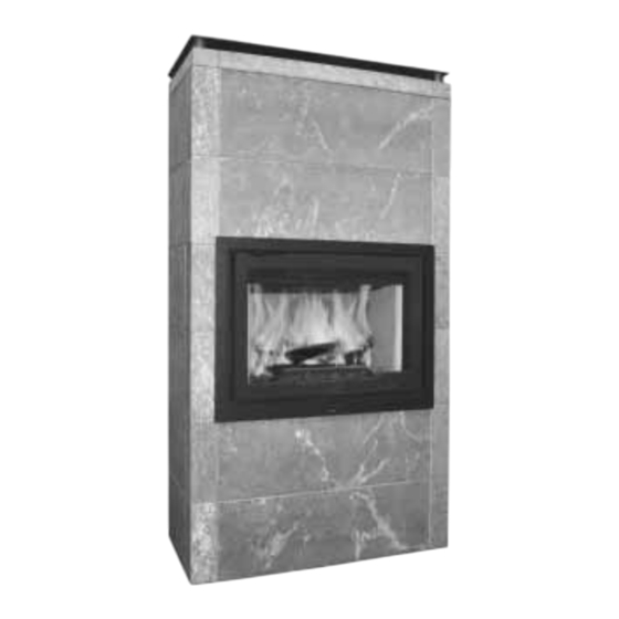
Jøtul FS 166 - I 570
Monterings- og bruksanvisningen må oppbevares under hele produktets levetid. These instructions
must be kept for future references. Ce manuel doit être conservé pour de futures interventions. Wir
empfehlen Ihnen, die Montage- und Bedienungsanleitung für spätere Zwecke sorgfältig aufzubewahren.
Jøtul FS 166 - I 570
2
11
20
29
38
47
Advertisement

Subscribe to Our Youtube Channel
Related Manuals for Jøtul FS 166


Summary of Contents for Jøtul FS 166
- Page 1 All manuals and user guides at all-guides.com Jøtul FS 166 - I 570 - Monterings- og bruksanvisning - Installation and Operating Instructions - Manuel d’installation et d’utilisation - Manual de instrucciones - Installazione e Istruzioni per l’uso - Instrukcja Montażu i Obsługi Jøtul FS 166 - I 570...
- Page 2 Forhold til myndighetene ......2 Tekniske data ..........2 Jøtul FS 166 - I 570 er et frittstående produkt av kleber der innsatsen, Jøtul I 570, brukes som brennkammer. Produktet kan plasseres mot brennbar vegg med de avstander som er Omrammingens deler ......4 beskrevet i fi...
- Page 3 All manuals and user guides at all-guides.com Jøtul FS 166 - I 570 Fig. 1 Mål i henhold til EN 13240 Min. mål gulvplate X,Y = I henhold til nasjonale lover og regler. 1025 Brennbar vegg 900079-P01...
- Page 4 All manuals and user guides at all-guides.com NORSK 3.0 Omrammingens deler Fig. 2...
- Page 5 4.2 Tildekking av gulv Det følger 2 manualer med produktet: 1. Jøtul FS 166 - I 570 (omrammingen) Jøtul FS 166 - I 570 har tett bunnplate og trenger ingen ekstra 2. Jøtul I 570 (brennkammeret) tildekking mot gulv under produktet.
- Page 6 All manuals and user guides at all-guides.com NORSK 4.9 Klargjøring av innsats (fi g. 3B-E). Se avsnitt ”4.1 Utskifting av brennplater/ hvelv/ledeplate.” NB! Kontroller at ildstedet er fritt for skader før installasjonen begynner. Produktet er tungt! Sørg for hjelp når det skal settes opp og monteres.
- Page 7 All manuals and user guides at all-guides.com NORSK Fig. 6 Fig. 8 A Fest de 4 kassettbeina (fi g. 6 A) til innsatsen med skruene. Skru i fotskruene (fi g. 6 B) på kassettbeina. Juster til riktig NB! Hull i gulv til uteluft. lengde (se fi...
- Page 8 All manuals and user guides at all-guides.com NORSK Fig. 9 Fig. 11 brakett 1 brakett 2 brakett 4 brakett 3 brakett 5 brakett 6 Fig. 10 Løft innsatsen opp på stativet. Vær forsiktig da innsatsen er fortung. Sett på plass igjen alle delene som ble fjernet for å lette håndteringen av innsatsen.
- Page 9 All manuals and user guides at all-guides.com NORSK Fig. 12-2 Fig. 14 Bruk brakett 5 (fi g. 14 A) på lag nr. 3 og 4. Juster om nødvendig brakettene for hånd slik at de klemmer steinene best mulig sammen. NB! Før bruk - åpne dæren og fjern skruen (fi g 12-2 A) Fig.
- Page 10 All manuals and user guides at all-guides.com NORSK 6.0 Ferdig montert Fig. 16 Se den generelle bruks- og vedlikeholdsmanual for Jøtul I 570 vedr. bruk og vedlikehold av produktet! 7.0 Vedlikehold Skulle man være uheldig å få riper i overfl aten, kan det pusses med et fi...
- Page 11 Relationship with the authorities ..11 Technical data........11 Jøtul FS 166 – I 570 is a freestanding product with Jøtul I 570 as the burn chamber, which can be positioned against infl ammable walls at the distances described in Fig. 1.
- Page 12 All manuals and user guides at all-guides.com Jøtul FS 166 - I 570 Fig. 1 Measurements according to EN 13240 Min. measurements floor plate X / Y= Acc. to national regulatives and regulations. 1025 Combustible wall 900079-P01...
- Page 13 All manuals and user guides at all-guides.com ENGLISH 3.0 Parts of the surround Fig. 2...
- Page 14 Heat shield, top 1 pcs Adjustable leg 4 pcs Make sure the room where the Jøtul FS 166 - I 570 is to be Heat shield for fl ue pipe 1 pcs placed has a ceiling height of at least 2300 mm.
- Page 15 All manuals and user guides at all-guides.com ENGLISH 4.9 Preparation/installation Fig. 3 C NB: Check that the fireplace is undamaged before installation begins. The product is heavy! Ensure you have help when positioning and installing it. After unpacking the insert take out the box with contents. To make the product lighter, remove the door.
- Page 16 All manuals and user guides at all-guides.com ENGLISH Fig. 5 Fig. 7 Dismount the insert’s heat shield by unscrewing the upper screw on both sides of the insert (fi g. 5 A). Loosen the lower screws (fi g. 5 E) somewhat and pull the heat shield upwards and then remove it.
- Page 17 All manuals and user guides at all-guides.com ENGLISH Fig. 8 B Fig. 10 50 mm NB!: Do not use corner stones marked «223628» before Assemble the stand. The stand consist of bottom plate the fourth layer. (Fig. 8 B-A), 4 legs (Fig. 8 B-B) and top plate (Fig. 8 B-C). Fit the fi...
- Page 18 All manuals and user guides at all-guides.com ENGLISH Fig. 12 Fig. 13 4 psc. M10x35 Centre the insert laterally. Position the insert and the frame against the front of the surround. Remove the lower cover (Fig.12 A). Make sure that there is clearance between the lower edge Fit the decorative frame over the door and hook it over the of the frame and the stone below (Fig.
- Page 19 All manuals and user guides at all-guides.com ENGLISH Fig. 15 Fig. 17 223628 Place the attachment bracket on the special corner stone 223628 (Fig. 15 A). The front stone (Fig. 15 B) of layer 5 shall rest on the attachment bracket. If top smoke outlet: Fig.
- Page 20 Rapports avec les autorités ....20 Données techniques ......20 Le Jøtul FS 166 – I 570 est un appareil indépendant dont le foyer Jøtul I 570 peut se placer contre des murs infl ammables conformément aux distances décrites en fi g. 1.
- Page 21 All manuals and user guides at all-guides.com Jøtul FS 166 - I 570 Fig. 1 Dimensions suivant EN 13240 Dimensions minimales de la plaque de sol X/Y = Conformes auz lois et règlements en vigueur. 1025 Mur en matériau combustible...
- Page 22 All manuals and user guides at all-guides.com FRANCAIS 3.0 Vue éclatée de l’habillage Fig. 2...
- Page 23 4 pces Veillez à ce que la pièce dans laquelle sera intallé le poêle Jøtul Bride 5 4 pces FS 166 - I 570 ait une hauteur de plafond d’au moins 2 300 mm. Bride 2 6 pces Bride 4 4 pces 4.7 Cheminée et conduits...
- Page 24 All manuals and user guides at all-guides.com FRANCAIS Avant l’installation, déterminez les points suivants: Fig. 3 C 1. L’emplacement de la sortie d’évacuation des fumées. 2. LLe système de collecte des cendres, si utilisé. Reportez-vous aux manuels correspondants pour les instructions d’installation des pièces.
- Page 25 All manuals and user guides at all-guides.com FRANCAIS Fig. 5 Fig. 7 Démontez le bouclier thermique de l’insert en dévissant Dévissez le bouclier thermique supérieur à l’arrière (fi g. les vis supérieures de chaque côté de l’insert (fi g. 5 A). 7 A).
- Page 26 All manuals and user guides at all-guides.com FRANCAIS Fig. 8 B Fig. 10 50 mm Assemblez le socle. Celui-ci se compose de la plaque de Remarque : La pierre d’angle 223628 se place au troisième fond (fi g. 8 B-A), de 4 pieds (fi g. 8 B-B) et de la plaque rang.
- Page 27 All manuals and user guides at all-guides.com FRANCAIS Fig. 12 Fig. 13 4 psc. M10x35 Centrez l’insert latéralement. Positionnez-le ainsi que le cadre contre la façade de l’habillage. Enlevez le demi cadre inférieur (fi g.12 A). Veillez à ménager un dégagement entre le bord inférieur Ajustez le cadre décoratif au-dessus de la porte et du cadre et la pierre du dessous (fi...
- Page 28 All manuals and user guides at all-guides.com FRANCAIS 6.0 Après l’installation Fig. 16 Pour l’utilisation au quotidien et l’entretien, voir le manuel d’utilisation générale et de maintenance du poêle. 7.0 Maintenance Si les surfaces présentent des rayures, celles-ci peuvent être polies au moyen de papier abrasif à...
- Page 29 Relación con las autoridades .....29 Datos técnicos ........29 Jøtul FS 166 – I 570 es un producto separado que utiliza Jøtul I 570 como cámara de combustión y puede colocarse junto a paredes infl amables a las distancias indicadas en la Fig. 1.
- Page 30 All manuals and user guides at all-guides.com Jøtul FS 166 - I 570 Fig. 1 Measurement s according t o EN 13240 Dimensiones mínimas de la placa de piso X/Y = De conformidad con las leyes y reglamentos nacionales. 1025...
- Page 31 All manuals and user guides at all-guides.com ESPAÑOL 3.0 Partes del revestimiento Fig. 2...
- Page 32 Compruebe que la altura del techo en la habitación donde se Soporte 1 6 uds. va a instalar la Jøtul FS 166 - I 570 es de al menos 2.300 mm. Soporte 3 uds. 4.7 Chimenea y tubo de tiro Soporte 6 4 uds.
- Page 33 All manuals and user guides at all-guides.com ESPAÑOL Tornillo avellanado, M6x16 8 uds. Fig. 3 B Escudo térmico superior 1 uds. Pata ajustable 4 uds. Escudo térmico para tubería de humos 1 uds. Tornillo de cabeza hexagonal, M10x35 4 uds. Tornillo de cabeza hexagonal con brida, M6x10 2 uds.
- Page 34 All manuals and user guides at all-guides.com ESPAÑOL 5.0 Instalación Fig. 6 Nota: La base tiene que estar nivelada con una tolerancia máxima de 1 mm/m. Esto es muy importante para que el resto de la instalación sea correcta. Todas las piedras deben estar niveladas. Compruebe la nivelación de cada nueva capa de piedras.
- Page 35 All manuals and user guides at all-guides.com ESPAÑOL Fig. 8 A Fig. 9 soporte 1 soporte 2 soporte 2 soporte 4 soporte 3 soporte 5 soporte 6 Nota: Orifi cios en el piso para aire externo. Fig. 10: Fig. 8 B 50 mm Nota: No se deben utilizar las piedras de esquina marcadas 223628 hasta la capa cuarta.
- Page 36 All manuals and user guides at all-guides.com ESPAÑOL Fig. 11 Fig. 12.2 Nota: Antes de usar, abra la puerta, Coloque la cámara de combustión sobre la base. y retire el tornillo (fi g. 12.2 - A). Asegúrese de que la cámara de combustión está en una posición estable.
- Page 37 All manuals and user guides at all-guides.com ESPAÑOL Fig. 17 Fig. 14 Use el soporte 5 (Fig. 14 A) en las capas 3 y 4. Si es necesario, ajuste los soportes con las manos de modo que sujeten las piedras. En caso de salida de humo superior: Fig.
- Page 38 Indice generale Conformità alle leggi ......38 Jøtul FS 166 – I 570 è un prodotto mobile che utilizza come camera di combustione il modello Jøtul I 570 ed è posizionabile contro pareti infi ammabili alle distanze indicate in Fig. 1.
- Page 39 All manuals and user guides at all-guides.com Jøtul FS 166 - I 570 Fig. 1 Dati con referimento alla norma EN 13240 Dimensioni minime per la piastra di protezione del pavimento X/Y = In conformità alle leggi e alle normative nazionali.
- Page 40 All manuals and user guides at all-guides.com ITALIANO 3.0 Componenti per il rivestimento Fig. 2...
- Page 41 1 qtà Assicurarsi che il locale in cui verrà posizionato il prodotto Staff a 1 6 qtà Jøtul FS 166 - I 570 presenti un’altezza dal soffi tto di almeno Staff a 3 10 qtà 2300 mm. Staff a 6 4 qtà...
- Page 42 All manuals and user guides at all-guides.com ITALIANO Staff a 2 6 qtà Fig. 3 C Staff a 4 4 qtà Vite a testa svasata, M6x16 8 qtà Scudo termico superiore 1 qtà Gamba regolabile 4 qtà Scudo termico per la canna fumaria 1 qtà Vite a testa esagonale, M10x35 4 qtà...
- Page 43 All manuals and user guides at all-guides.com ITALIANO Fig. 5 Fig. 7 Svitare lo scudo termico superiore sul retro (fi g. 7 A). Capovolgerlo e avvitarlo saldamente usando le stesse viti a cui era fi ssato in precedenza. 4. Smontare lo scudo termico dell’inserto svitando la vite In presenza di uno scarico fumi superiore: Montare lo superiore posta su entrambi i lati dell’inserto (fi...
- Page 44 All manuals and user guides at all-guides.com ITALIANO Fig. 8 B Fig. 10 50 mm NB non usare Le pietre ad angolo, marcate 223628, sino al Montare il supporto, composto dalla piastra inferiore (fi g. 8 4 livello come in fi g 15 B- A), dai 4 montanti (fi...
- Page 45 All manuals and user guides at all-guides.com ITALIANO Fig. 12 Fig. 13 4 psc. M10x35 Centrare lateralmente l’inserto. Posizionare l’inserto e la cornice contro la parte anteriore Rimuovere la copertura inferiore (Fig.12 A). del rivestimento. Inserire la cornice decorativa sulla porta e agganciarla Verifi...
- Page 46 All manuals and user guides at all-guides.com ITALIANO Fig. 15 In presenza di uno scarico fumi superiore: Collocare l’ultimo strato (Fig. 17 A) e lo strato superiore (Fig. 17 B). Utilizzare la staff a 2, 4 e 6 tra l’ultimo strato e lo strato superiore (Fig.
- Page 47 Zgodność z przepisami .......47 Dane techniczne ........47 Jøtul FS 166 – I 570 to produkt w wersji wolno stojącej z Jøtul I 570 jako komora spalania, która może być umieszczona przy ścianach wykonanych z materiałów łatwopalnych w Części obudowy ........49 odległościach określonych na Rys.
- Page 48 All manuals and user guides at all-guides.com Jøtul FS 166 - I 570 Rys 1 Odległości i wymiary według normy EN 13240 Min. wymiary płyty podłogowej X / Y= zgodnie z przepisami obowiązującymi w danym kraju. 1025 Ściana z materiału łatwopalnego...
- Page 49 All manuals and user guides at all-guides.com POLSKI 3.0 Części obudowy Rys. 2...
- Page 50 1 szt. Należy upewnić się czy sufit w pomieszczeniu, w którym Wspornik 1 6 szt. kominek Jøtul FS 166 – I 570 ma być zamontowany, posiada Wspornik 3 10 szt. minimalną wymaganą do tego celu wysokość - 2300mm. Wspornik 6...
- Page 51 All manuals and user guides at all-guides.com POLSKI Wspornik 5 4 szt. Rys. 3 B Wspornik 2 6 szt. Wspornik 4 4 szt. Śruba z łbem wpuszczanym, M6x16 8 szt. Blacha osłonowa górna 1 szt. Noga nastawna 4 szt. Blacha osłonowa rury dymowej 1 szt.
- Page 52 All manuals and user guides at all-guides.com POLSKI 5.0 Montaż Rys. 6 Uwaga! Podstawa musi być wypoziomowana. Maks. zakres tolerancji wynosi 1mm/m. By pozostałe e t a p y m o n t a ż u p r z e b i e g ł y p r a w i d ł o w o , n a l e ż y zastosować...
- Page 53 All manuals and user guides at all-guides.com POLSKI Fig. 8 A Rys. 9 Wspornik 1 Wspornik 2 Wspornik 4 Wspornik 3 Wspornik 5 Wspornik 6 Uwaga! Otwór w podłodze na ujęcie świeżego powietrza. Rys. 10 Rys. 8 B 50 mm Uwaga! Nie używać...
- Page 54 All manuals and user guides at all-guides.com POLSKI Rys. 11 Rys. 13 4 psc. M10x35 Umieścić wkład kominkowy ukośnie. Ustawić wkład i ramę na przodzie obudowy. Upewnić się, czy luka pomiędzy dolną krawędzią ramy i Umieścić komorę spalania na podstawie. Upewnić się czy kamieniem znajdującym się...
- Page 55 All manuals and user guides at all-guides.com POLSKI Rys. 15 Rys. 17 223628 Umieścić wspornik mocujący na specjalnym narożniku kamiennym 223628 (Rys. 15A). Kamień przedni (Rys. 15B) warstwy 5 ma spoczywać na tym wsporniku mocującym. Rys. 16 W przypadku górnego przejścia kominowego: Umieścić...
- Page 56 All manuals and user guides at all-guides.com POLSKI 6.0 Po zakończeniu montażu By uzyskać informacje na temat eksploatacji i konserwacji urządzenia, należy zapoznać się z ogólną instrukcją eksploatacji i konserwacji dla kominka Jøtul I 570. 7.0 Konserwacja Jeśli po przeprowadzonym montażu znajdziemy rysy na powierzchni, możemy je wypolerować...
- Page 57 All manuals and user guides at all-guides.com SPRÅK...
- Page 58 All manuals and user guides at all-guides.com SPRÅK...
- Page 59 All manuals and user guides at all-guides.com SPRÅK...
- Page 60 All manuals and user guides at all-guides.com Jøtul arbeider kontinuerlig for om mulig å forbedre sine produkter, og vi forbeholder oss retten til å endre spesifi kasjoner, farger og utstyr uten nærmere kunngjøring. Jøtul bemüht sich ständig um die Verbesserung seiner Produkte, deshalb können Spezifi kationen, Farben und Zubehör von den Abbildungen und den Beschreibungen in der Broschüre abweichen.
Need help?
Do you have a question about the FS 166 and is the answer not in the manual?
Questions and answers