
Related Manuals for ABB MT567


Summary of Contents for ABB MT567
- Page 1 — LOW VO LTAG E S W I TC H G E A R Wireless Temperature Monitor MT567 User Manual • Direct continuous temperature monitoring of critical connections, for higher safety and continuous power distribution availability...
- Page 2 Temperatures are measured using wireless temperature sensors STX300 series, installed within the assembly. Any change in temperature is observed and informed by the wireless temperature monitoring device MT567. For a peace of mind.
- Page 3 Document revision history 08-09 Cyber security disclaimer Legal disclaimer Secure network integration Network security hardening guidelines 10-11 Product overview Overview Main unit MT567 Operator panel MP53/MP56 Wireless temperature sensor STX311/STX313 Material 12-14 Mounting MT567 DIN-rail mounting MT567 screw mounting STX311/STX313 sensor mounting...
- Page 4 15-16 Interfaces MT567 terminals Terminal connection diagram 17-20 Function Temperature monitoring Parameter description 21-25 Communication Communication with ZigBee Green Power Communication with Modbus TCP 26-34 Operator panel MP53/56 Operator panel Display pages and navigation Device temperature and humidity STX sensor temperature...
- Page 5 Removal of the device Replacement of the device Disposal handling 37-39 Cyber security guidelines General Cryptographic and security functionalities Default network ports used by MT567 Secure commissioning Secure operation Secure maintenance Secure decommissioning How to contact us 40-48 Appendix A: Register map...
- Page 6 General Target group The manual is primarily intended for those requiring information on the applications of MT567 for the purpose of understanding, engineering, wiring & operating the product. The objective of this manual is to provide the technical functions description of MT567.This manual should be studied carefully before installing, parameterizing or operating the controller.
- Page 7 2NGA000585 STX300 User Manual 1TNA810071 Wireless Temperature Monitoring assembly instruction 1TGC908001 ABB Ability Condition Monitoring for electrical systems - CMES - User Manual Related system version The content of this document is related to the products with the following hardware and firmware version release.
- Page 8 Other than under explicit contractual commitments, in no event shall ABB be responsible or liable for any loss or damage resulting from a system failure and/or product failure would create a risk for harm to property or persons (including but...
- Page 9 To report a suspected problem or to get the latest information about cybersecurity, visit the ABB Cybersecurity Portal or send an email: Web: https://www.abb.com/cybersecurity...
- Page 10 STX311/STX313 to measure the temperature of critical electrical connection in a switchgear assembly. MT567 can either send the temperature data over a Modbus TCP communication network e.g. to the online condition monitoring system ABB CMES or also directly display the temperature through MP53/MP56.
- Page 11 Monitoring and operation can be done through the LCD display and the control button on the MP53 or MP56 panel. Each MT567 main unit can connect to only one operator panel.
- Page 12 The MT567 device is designed to be installed with the switchgear assembly where access is restricted. It is recommended to mount the MT567 in the front door of the cabinet. Access to the cabinet shall be for authorized personnel only.
- Page 13 MT567 screw mounting The device can be installed on a mounting plate using self-tapping screws (M4). Wall mounting with screws is allowable. — Fig. 6 Drilling pattern for MT567 screw mounting — Fig. 7 Screw mounting of MT567 STX311/STX313 sensor mounting...
- Page 14 W I R E L E S S T E M P E R AT U R E M O N I T O R M T 5 6 7 U S E R M A N U A L MP53/56 operating panel mounting —...
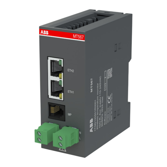
- Page 15 M O U N T I N G / I N T E R FA C E S — Interfaces MT567 terminals — Fig. 11 Terminal Layout of MT567 Terminal designations — Table 1: MT567 Terminal description Terminal name Designation...
- Page 16 — Fig. 14 MT567 and MP56 MP53/56 is connected to MT567 via the MP port. The MP port is provided as a RJ12 socket. The cables for the connections are pre-assembled and must be used together with the panel. Connection cable between MT567 and MP53/56 panel: TA211: L = 1.2m...
- Page 17 Function Temperature monitoring MT567 monitors the temperature sensors installed at critical electrical connection in the switchgear, including the joint of main busbar connection at transport section, the ACB cable or busway connections and larger outgoing cable connection etc. to detect bad connections, which may lead to unwanted temperature rise, and even more severe failure in the switchgear.
- Page 18 Sensor group parameters There are 15 sensor groups on MT567, for up to 60 STX sensors. The first STX to the fourth STX, connected to MT567, belong to the 1st Group, and so on to the 57th to 60th sensor belonging to the 15th Group.
- Page 19 F U N C T I O N Digital output parameter MT567 provides one relay output, and the users can define its function according to actual needs. The programmable output functions are as below: Parameters Setting Range Factory Setting Digital Output Function...
- Page 20 (Can be changed by the user) The wireless parameters only can be changed through Modbus TCP. Sensor Communication Failure Delay: the time how long MT567 waits when no data are received from wireless temperature sensors to trigger the alarm. Wireless Radio Channel: the operation wireless radio channel of ZigBee.
- Page 21 MT567 uses star network architecture, where a host coordinator communicates with up to 60 slave end-devices. The 60 end-devices are the STX temperature sensors that collect temperature data and send it to the host. MT567 as the coordinator will process the temperature values and calculate alarm values.
- Page 22 — Fig. 18 MT567 connected to Ethernet network Modbus TCP characteristics MT567 has a 2-port Ethernet switch embedded, which permits a flexible network design. The characteristics for connection to the network are as follows: — Table 2: Modbus TCP network characteristics...
- Page 23 In a star topology, each MT567 must connect to a switch via RJ45 as follows: — Fig. 19 Star connection Bus topology Two RJ45 ethernet ports of MT567 are used to connect between MT567 interfaces or between MT567 and a switch. The bus connection is illustrated as below: — Fig. 20 Bus connection Ring topology with network redundancy A ring topology is a daisy chain where the last device in the chain loops back to the managed switch.
- Page 24 MRP manager, which is typically a managed network switch, and MRP clients which are typically devices like MT567. The MRP master sends out test telegrams cyclically to check the health status of the network. If everything is ok, it blocks telegrams on one side of its internal switch to avoid loops (left side of the next figure).
- Page 25 The value 0xFF must be used. Modbus TCP default port: 502. Function code: This is the second byte of every transmission. MT567 support function code 03H, 04H, 06H, and 10H. In a master request transmission, the function code tells the slave what action to perform.
- Page 26 Operator panel MP53/56 Operator panel Operator panel MP53/MP56 is an optional accessory for local operation and parameter setting of MT567. Operator panel is connected to MT567 device via RJ12 interface which is located on the back of the panel. —...
- Page 27 Device temperature and humidity After power on, MP53/MP56 initially enters the first display page (Fig. 24 Initial display page). This page shows the temperature and humidity from onboard sensor in MT567. If values are indicated here, the device is working properly.
- Page 28 “--” ⑤ The total number of configured STX sensors for this MT567 ⑥ The numerical order of the STX sensor Push Down button to switch to the next STX sensor temperature display or push Up button to switch to the previous one.
- Page 29 A_ETH1_ERR Ethernet physical interface1 alarm occurs under MRP scenario A_ETH2_ERR Ethernet physical interface2 alarm occurs under MRP scenario A_MAC_ERR The MAC address is invalid A_BOOT2_C The FW of boot2 was corrupted A_ZBM_ERR The ZigBee module inside MT567 communication is failed...
- Page 30 Parameter configuration pages The following MT567 parameters can be configured with the MP panel: • Network communication setting • STX sensor pairing, enable/disable Following table 8 is an overview of configuration menu.
- Page 31 O P E R ATO R PA N E L M P 5 3/ 5 6 Setting procedure - step by step To set a value, perform the following steps: Press the button. The page goes to the password page. Input the pin code (the default value is 1111, for security consideration, the default pin code is suggested to be changed).
- Page 32 W I R E L E S S T E M P E R AT U R E M O N I T O R M T 5 6 7 U S E R M A N U A L Network setting The default network parameter settings: IP address ->...
- Page 33 O P E R ATO R PA N E L M P 5 3/ 5 6 — Fig. 29 Password setting Enable/Disable STX sensor All the STX sensors are enabled by default and must disabled if the corresponding STX sensor is not used to avoid unnecessary alarm messages. The Example in Fig.30 show how to disable the 2nd index of STX sensor.
- Page 34 To pair STX sensor successfully, make sure only one STX sensor and one MT567 is in pairing mode at the same time. Avoid other sensors being paired at the same time nearby.
- Page 35 — Maintenance The MT567 is a battery-less, external powered device and does not require any maintenance. The STX sensor is a battery-less device, powered by installation on conductors. It does not require any maintenance. The STX sensor requires min 5A current on the bus bar for its intended operation.
- Page 36 Removal, repair or replacement Product life cycle With a MTBF of >90 years for the wireless temperature monitor MT567 and >45 years for the STX 300 series sensors, the solution is ready to operate throughout the life of the switchgear. However, new technologies or upgrade solution might be provided in future.
- Page 37 Modbus TCP network as part of an electrical switchgear assembly. It can be used together with other devices communicating on the same network. Data are read by the ABB Ability™ CMES Edge device or other monitoring systems connected to the same network. The CMES acts further as a gateway to isolate the OT and IT different networks.
- Page 38 MConfig has been disconnected for 30min or device reboot. Secure commissioning MT567 and STX sensors will be commissioned at the switchgear factory or at the installation site for the switchgear. Authorized user can securely commission by following below steps: 1.Before making any settings in MT567 using the operator panel MP53/56, change the default...
- Page 39 Secure decommissioning In the event of the MT567 or MP53/56 reaching its end of life or the devices are no longer in use it is recommended to remove any specific network IP address this product might be used in.
- Page 40 W I R E L E S S T E M P E R AT U R E M O N I T O R M T 5 6 7 U S E R M A N U A L —...
- Page 41 A P P E N D I X A : R E G I S T E R M A P The product device code of MT567 is fixed as 1TGD120501R0001 The version has two chars; the high bytes is the main version and the low byte is the subversion.
- Page 42 W I R E L E S S T E M P E R AT U R E M O N I T O R M T 5 6 7 U S E R M A N U A L Register Value Range Address...
- Page 43 A P P E N D I X A : R E G I S T E R M A P Monitoring values Register Value Range Address Data Type/ (Default Group (Hex) Value Name Format Step Unit setting) Onboard Sensor 0050 Temperature Integer...
- Page 44 W I R E L E S S T E M P E R AT U R E M O N I T O R M T 5 6 7 U S E R M A N U A L Register Value Range Address...
- Page 45 A P P E N D I X A : R E G I S T E R M A P Holding registers Temperature alarm group Register Value Range Address Data Type/ (Default Group (Hex) Value Name Format Step Unit setting) Temperature Alarm 1025...
- Page 46 W I R E L E S S T E M P E R AT U R E M O N I T O R M T 5 6 7 U S E R M A N U A L Output relay Register Value Range...
- Page 47 A P P E N D I X A : R E G I S T E R M A P STX sensor setting Register Value Range Address Data Type/ (Default Group (Hex) Value Name Format Step Unit setting) Sensor Enable 10A0 Sensor Enable Flag 1 10A1...
- Page 48 ASCII All the paired STX sensors will be removed when changing the Wireless Radio Channel. The STX sensors need to be repaired if they are still to be connected to MT567. The “…” omit the situation of from the 2 to 59 sensor source ID.
- Page 49 A P P E N D I X A : R E G I S T E R M A P / A P P E N D I X B : D ATA F O R M AT — Appendix B: Data format Format Code Description...
- Page 50 W I R E L E S S T E M P E R AT U R E M O N I T O R M T 5 6 7 U S E R M A N U A L Format Code Description Value (HEX)
- Page 51 A P P E N D I X B : D ATA F O R M AT Format Code Description Value (HEX) Sensor 03 channel 1 temperature alarm 0100 Sensor 03 channel 2 temperature alarm 0200 Sensor 03 channel 3 temperature alarm 0400 Reserved 0800...
- Page 52 W I R E L E S S T E M P E R AT U R E M O N I T O R M T 5 6 7 U S E R M A N U A L Format Code Description Value (HEX)
- Page 53 A P P E N D I X B : D ATA F O R M AT Format Code Description Value (HEX) Reserved 0080 Sensor 15 channel 1 temperature alarm 0100 Sensor 15 channel 2 temperature alarm 0200 Sensor 15 channel 3 temperature alarm 0400 Reserved 0800...
- Page 54 W I R E L E S S T E M P E R AT U R E M O N I T O R M T 5 6 7 U S E R M A N U A L Format Code Description Value (HEX)
- Page 55 A P P E N D I X B : D ATA F O R M AT Format Code Description Value (HEX) Sensor 26 channel 3 temperature alarm 0040 Reserved 0080 Sensor 27 channel 1 temperature alarm 0100 Sensor 27 channel 2 temperature alarm 0200 Sensor 27 channel 3 temperature alarm 0400...
- Page 56 W I R E L E S S T E M P E R AT U R E M O N I T O R M T 5 6 7 U S E R M A N U A L Format Code Description Value (HEX)
- Page 57 A P P E N D I X B : D ATA F O R M AT Format Code Description Value (HEX) Sensor 38 channel 2 temperature alarm 0020 Sensor 38 channel 3 temperature alarm 0040 Reserved 0080 Sensor 39 channel 1 temperature alarm 0100 Sensor 39 channel 2 temperature alarm 0200...
- Page 58 W I R E L E S S T E M P E R AT U R E M O N I T O R M T 5 6 7 U S E R M A N U A L Format Code Description Value (HEX)
- Page 59 A P P E N D I X B : D ATA F O R M AT Format Code Description Value (HEX) Sensor 50 channel 1 temperature alarm 0010 Sensor 50 channel 2 temperature alarm 0020 Sensor 50 channel 3 temperature alarm 0040 Reserved 0080...
- Page 60 W I R E L E S S T E M P E R AT U R E M O N I T O R M T 5 6 7 U S E R M A N U A L Format Code Description Value (HEX)
- Page 61 A P P E N D I X B : D ATA F O R M AT Format Code Description Value (HEX) Sensor 04 communication alarm 0008 Sensor 05 communication alarm 0010 Sensor 06 communication alarm 0020 Sensor 07 communication alarm 0040 Sensor 08 communication alarm 0080...
- Page 62 W I R E L E S S T E M P E R AT U R E M O N I T O R M T 5 6 7 U S E R M A N U A L Format Code Description Value (HEX)
- Page 63 A P P E N D I X B : D ATA F O R M AT Format Code Description Value (HEX) Sensor 51 communication alarm 0004 Sensor 52 communication alarm 0008 Sensor 53 communication alarm 0010 Sensor 54 communication alarm 0020 Sensor 55 communication alarm 0040...
- Page 64 W I R E L E S S T E M P E R AT U R E M O N I T O R M T 5 6 7 U S E R M A N U A L Format Code Description Value (HEX)
- Page 65 A P P E N D I X B : D ATA F O R M AT Format Code Description Value (HEX) 2= Reserved 0002 3= update parameters 0003 4= Reserved 0004 5= Set parameters from MP 0005 6= Reserved 0006 7= Set parameters from Modbus 0007...
- Page 66 W I R E L E S S T E M P E R AT U R E M O N I T O R M T 5 6 7 U S E R M A N U A L Format Code Description Value (HEX)
- Page 67 A P P E N D I X B : D ATA F O R M AT Format Code Description Value (HEX) Sensor 19 0004 Sensor 20 0008 Sensor 21 0010 Sensor 22 0020 Sensor 23 0040 Sensor 24 0080 Sensor 25 0100 Sensor 26...
- Page 68 W I R E L E S S T E M P E R AT U R E M O N I T O R M T 5 6 7 U S E R M A N U A L Format Code Description Value (HEX)
- Page 69 A P P E N D I X B : D ATA F O R M AT / A P P E N D I X C : T E C H N I C A L D ATA — Appendix C: Technical data MT567 technical data Voltage inputs* Rated operational voltage (Ue)
- Page 70 W I R E L E S S T E M P E R AT U R E M O N I T O R M T 5 6 7 U S E R M A N U A L Zigbee Frequency range 2405 MHz~2480 MHz...
- Page 72 — ABB Xiamen Low Voltage Equipment Co., Ltd. 361101 No.881, FangShanXiEr Road, Xiang'an District, Xiamen, Fujian Tel: +86 592 6038118 Fax: +86 592 6038110 http://www.abb.com/mns We reserve the right to make technical We reserve all rights in this document and...
Need help?
Do you have a question about the MT567 and is the answer not in the manual?
Questions and answers