Advertisement
Quick Links
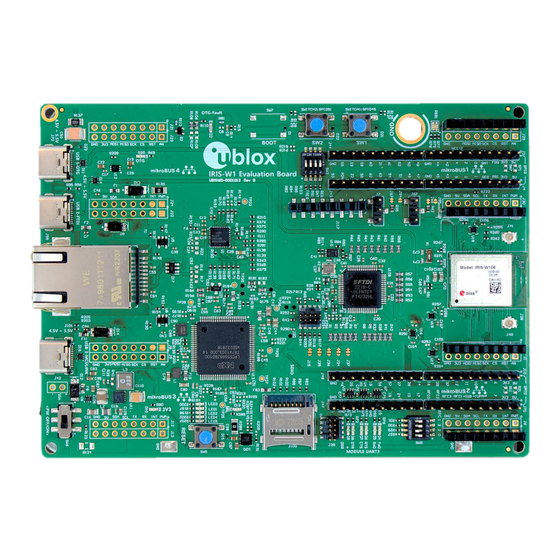
EVK-IRIS-W10
Evaluation kit for IRIS-W10 series modules
User guide
Abstract
This document describes how to set up and use the EVK-IRIS-W10 evaluation kits for prototyping
the IRIS-W10 open CPU, multiradio modules. It also describes the different options for debugging
and the development capabilities included in the evaluation board.
UBX-23007837 - R03
C1-Public
www.u-blox.com
Advertisement

Subscribe to Our Youtube Channel
Related Manuals for Ublox EVK-IRIS-W10


Summary of Contents for Ublox EVK-IRIS-W10
- Page 1 User guide Abstract This document describes how to set up and use the EVK-IRIS-W10 evaluation kits for prototyping the IRIS-W10 open CPU, multiradio modules. It also describes the different options for debugging and the development capabilities included in the evaluation board.
- Page 2 EVK-IRIS-W10 - User guide Document information Title EVK-IRIS-W10 Subtitle Evaluation kit for IRIS-W10 series modules Document type User guide Document number UBX-23007837 Revision and date 8-Nov-2024 Disclosure restriction C1-Public This document applies to the following products: Product name Document status...
- Page 3 EVK-IRIS-W10 - User guide Contents Document information ..........................2 Contents ................................3 Product description ..........................5 1.1 Overview ................................ 5 1.2 Kit includes ..............................5 1.2.1 EVK-IRIS-W101 ........................... 5 1.2.2 EVK-IRIS-W106 ........................... 5 1.3 Key features ..............................5 1.4 Block diagram .............................. 6 Setting up the evaluation board .......................
- Page 4 EVK-IRIS-W10 - User guide 3.12 Jumpers ..............................36 3.13 Test points ..............................38 Appendix ..............................39 Re-loading the Wi-Fi_CLI example ....................39 A.1 Prerequisite ..............................39 A.2 Flashing the firmware and application ....................39 Glossary ..............................41 Related documentation ........................... 42 Revision history ............................42 Contact ................................
- Page 5 COM ports, debugging, and USB peripheral connectors. Additionally, the board features other interfaces like Ethernet RJ45 and an SDIO header. The EVK-IRIS-W10 board is equipped with a Reset button, Boot button, and two user-configurable buttons. Current sense resistors are incorporated for accurate current measurement within the module.
- Page 6 • Peripherals : ADC, GPIO, I2C, Ethernet RMII, SDIO, SPI, UART 1.4 Block diagram Figure 1 shows the block diagram and internal connections of EVK-IRIS-W10. Figure 1: EVK-IRIS-W10 block diagram Not all peripherals available simultaneously UBX-23007837 - R03 Product description...
- Page 7 EVK-IRIS-W10 - User guide Setting up the evaluation board 2.1 Prerequisites Before starting up the board: 1. To configure the board to boot from QSPI flash (default), set the SW3 switch positions as shown below . See also Automatic bootloader / strap-in.
- Page 8 2.2.1 Wi-Fi example application The IRIS-W10 module hosted on the EVK-IRIS-W10 evaluation board is pre-flashed with the Wi-Fi CLI example application to conveniently experience the Wi-Fi features supported in the IRIS-W10 module – without the need of downloading the SDK and compiling any firmware.
- Page 9 Run iperf test using the wifi_CLI example This section assumes that the iperf test is run using two EVK-IRIS-W10 evaluation boards as devices – with Device A configured as an Access Point and Device B configured as a Station. Note that...
- Page 10 Macronix Memory. • For build versions from 23/46, the module is integrated with Fidelex Memory. 2.3.2 Flash and debug custom applications EVK-IRIS-W10 supports two options for flashing and debugging custom applications, using either: • MCU-Link port (On-board debugger) • External debugger 2.3.2.1...
- Page 11 EVK-IRIS-W10 - User guide Hardware description ☞ Design files for the EVK-IRIS-W10 are available in the u-blox short range EVK design GitHub repository [8]. Figure 3 shows the major functions provided by EVK-IRIS-W10. Figure 3: Header and major function locations 3.1 Power...
- Page 12 • Limit the maximum current to 600 mA by populating R124 with a 1206 0 Ω resistor 2A resistor and disconnecting U6. Figure 4: EVK-IRIS-W10 maximum current options 3.1.1.1 3.3 V switching regulator (U11) The EVB is populated with a fixed 3.3 V, 3 A, switching regulator (TPS62132RGTR), as shown in Figure 5.
- Page 13 EVK-IRIS-W10 - User guide 3.1.1.2 3.3 V Linear regulator (U20) Figure the NCP692MN33T2G regulator (U20) is intended to supply power to the MCU-LINK chip with minimum interference to the IRIS-W10 module. Figure 6: 3.3V linear regulator (U20) To configure power to MCU-LINK from the regulator, resistors R151, R144, and R288 must be populated with a 0 Ω, 0603 resistor, and R208, R145, R274, and R287 must be disconnected.
- Page 14 EVK-IRIS-W10 - User guide The maximum current capacity of the USB-OTG is 500 mA. LED D2 (Red) indicates whether the current to OTG-USB exceeds the current rating (800 mA). In this mode, the status of the USB-ID signal defines whether the EVB or IRIS-W10 module works as either an OTG host (supply the voltage to a device board), or an OTG device.
- Page 15 To bypass the current sense resistors, R35 and R62, solder the respective jumpers J94 and J95. ☞ The default hardware configuration doesn’t require any modification of the current-sense headers on EVK-IRIS-W10 to perform properly. 3.2 Reset The active-low reset signal, RESETn, is connected to the module PDn pin, the FTDI reset pin, the four mikroBUS slots, and a momentary button switch (SW5), as shown in Figure 11.
- Page 16 DIP switch SW3 positions determine the bootstrap method for booting the IRIS-W1 module. Figure 12: Bootloader schematic EVK-IRIS-W10 supports two main methods for bootstrapping the module: • Default method: This method uses DIP switch SW3 along with resistors R82, R94, R99, and R103.
- Page 17 EVK-IRIS-W10 - User guide 3.3 Buttons EVK-IRIS-W1 has two more momentary push-button switches. These switches are active-low or high and connect to ground or +3V3 when pressed. The buttons and the associated GPIO signals are shown Figure 13 Table Figure 13: EVK schematic - user buttons Table 3 describes the various user buttons and their relationship with the corresponding GPIO signals.
- Page 18 EVK-IRIS-W10 - User guide Figure 14 shows the schematic for the RGB status and power LEDs, and the configuration resistors (R77-R79). Figure 14: Schematic – RGB and power LED Figure 15 shows the UART3 status LEDs (D4–D9) that indicate UART3 signal status under GPIO control.
- Page 19 EVK-IRIS-W10 - User guide 3.5 Serial communication EVK-IRIS-W1 provides two options for serial communication and debugging: • MCU-Link (default) chip • FTDI chip 3.5.1 MCU-Link The MCU-Link is a powerful and cost-effective debug probe that seamlessly integrates with the MCUXpresso IDE. It is also compatible with third-party IDEs that support the CMSIS-DAP protocol.
- Page 20 EVK-IRIS-W10 - User guide IRIS-W10 GPIO/Function Connection MCU-Link pin GPIO 2/SPI0-MOSI Not default GPIO 3/SPI0-MISO Not default GPIO 4/SPI0-CLK Not default GPIO 5/ SPI0-SSELN1 Not default GPIO 13/SWD-CLK Default GPIO 14/SWD-SWDIO Default GPIO 16/FC2-I2C_SDA Not default GPIO 17/ FC2-I2C_SCL Not default...
- Page 21 EVK-IRIS-W10 - User guide 3.5.2 USB-to-UART FTDI EVK-IRIS-W1has two USB-to-UART FTDI chips that connect to the IRIS-W10 module over the serial interface: • Quad channel USB-to-UART IC (U108) • Single channel USB-to-UART IC (U109) Table 7 describes the connections to the IRIS-W10 module through U108, and U109. The main COM port 3 on the FTDI chip connects to UART3 on the module via 1 kΩ...
- Page 22 EVK-IRIS-W10 - User guide 3.6 JTAG/SWD debug interfaces There are two interfaces for debugging and programming IRIS-W10: SWD and JTAG. When powering up or resetting the EVK-IRIS-W10, the status of the RF-CNTL strapping pins determine the active interface, as described in Table...
- Page 23 EVK-IRIS-W10 - User guide The SWD/JTAG multiplex connections and default jumper positions are shown in Figure Figure 19: SWD/JTAG multiplex connections Jumpers described in Table 9 and shown Figure 20 should be set to their default connections. The default positions on the board are shown in...
- Page 24 Figure 21: Jumpers default connections 3.7 32.768 kHz low frequency clock EVK-IRIS-W10 is equipped with a 32.768 kHz crystal that can be used to supply the IRIS-W1 module as an external RTC clock source. GPIO21 and GPIO23 multiplex some of the RMII signals and the external crystal oscillator option.
- Page 25 EVK-IRIS-W10 - User guide 3.8 mikroBUS slots The EVK-IRIS-W10 features four mikroBUS standard-compatible slots, each offering multiple options for the RESET signal. By default, none of the slots are enabled for use. This is primarily because the Flexcomm interface pins in the NXP RW612 chip are multiplexed.
- Page 26 EVK-IRIS-W10 - User guide Table 11 outlines the default GPIO assignments for the analog, INT, and PWM signals on each mikroBUS slot. mikroBUS 1 mikroBUS 2 mikroBUS 3 mikroBUS 4 SDIO GPIO18 INT* SDIO-D2 GPIO27 PWM* GPIO46 GPIO47 GPIO48 GPIO49...
- Page 27 EVK-IRIS-W10 - User guide 3.8.1 mikroBUS 1 slot • UART is enabled by default through jumpers J25 and J27, as shown in Table • To enable I2C or SPI, adjust the state of jumpers J83 and J84 for SPI, or J80 and J85 for I2C, as shown in Figure 23.
- Page 28 EVK-IRIS-W10 - User guide 3.8.2 mikroBUS 2 slot • UART is enabled by default through jumpers J26 and J28, as shown in Table • To enable I2C or SPI, adjust the state of jumpers J81 and J86 for SPI, or J82 and J87 for I2C, as shown in Figure 24.
- Page 29 EVK-IRIS-W10 - User guide 3.8.3 mikroBUS 3 slot • UART is enabled by default through jumpers J16 and J18, as shown in Table • To enable I2C or SPI, adjust the state of jumpers J73 and J76 for SPI, or J11 and J79 for I2C, as shown in Figure 26.
- Page 30 EVK-IRIS-W10 - User guide 3.8.4 mikroBUS 4 slot • UART is enabled by default through jumpers J17 and J19, as shown in Table • To enable I2C or SPI, adjust the state of jumpers J74 and J77 for SPI, or J75 and J78 for I2C, as shown in Figure 27.
- Page 31 EVK-IRIS-W10 - User guide 3.9 RMII The EVK-IRIS-W10 supports RMII standard through 10BASE-T/100BASE-TX Physical Layer Transceiver U1 (KSZ8081MNXRNB) and 1 Port RJ45 Surface Mount 10/100 Base-T, AutoMDIX T1 (74980111211). RMII is enabled by default. However, there are four groups of resistors that demultiplex the RMII...
- Page 32 EVK-IRIS-W10 - User guide 3.9.1 RMII Strap-in options The strap-in pins are latched at the de-assertion of reset. During power-up or reset, the MAC RMII input pins can briefly drive high or low, which can unintentionally latch the RMII PHY strap-in pins into incorrect high or low states.
- Page 33 EVK-IRIS-W10 - User guide 3.10 Pin headers All GPIOS on IRIS-W10, except PSRAM-related GPIOs, are accessible on through-hole (TH) pin headers J3, J4, J10, J43, J44, J47, J48, and J70, as shown in Figure Figure 30: Pin headers GPIOs described in...
- Page 34 EVK-IRIS-W10 - User guide GPIO Header Pin Connection How to connect/disconnect other locations GPIO13 Not default Disconnect R257 and populate U19 and R258 with 10 kΩ resistor. Or populate R143 with a 0 Ω resistor. GPIO14 Not default Disconnect R257 and populate U19 and R258 with 10 kΩ resistor.
- Page 35 +5 V 6,8,9,10 Table 22: Power signals mapping to the pin headers 3.11 QSPI memory EVK-IRIS-W10 provides an option for external memory. A Quad SPI PSRAM (U2), shown in Figure 31 and described in Table 23, can be optionally mounted on the rear side of EVK board.
- Page 36 EVK-IRIS-W10 - User guide 3.12 Jumpers When configuring GPIO functionality, EVK-IRIS-W10 supports several solder-bridge jumpers. Read the instructions carefully before altering any jumper to determine how each function is configured. Several jumpers are wired in series to demultiplex GPIOs that have multiple functions.
- Page 37 EVK-IRIS-W10 - User guide Table 25 shows the default function and alternate function of each jumper – if applicable. Jumper Default connection Alternate function Connect GPIO8 to mikroBUS4 SCL Can’t be connected simultaneously with J73, J16 Connect USB-VBUS to IRIS-W10 VBUS pin...
- Page 38 EVK-IRIS-W10 - User guide Jumper Default connection Alternate function Bypass R35, VDD current sense resistor Can’t be used with J97 Bypass R62, VDD-IO current sense resistor Can’t be used with J96, J115, J116 Connect R62, VDD-IO current sense resistor to Can’t be used with J95, J115, J116...
- Page 39 Appendix A Re-loading the Wi-Fi_CLI example The IRIS-W10 module hosted on the EVK-IRIS-W10 evaluation board is pre-flashed with the Wi-Fi CLI example application. If the application is overwritten or otherwise deleted or corrupted from where it resides in the flash memory, this appendix information describes how to re-load this application.
- Page 40 EVK-IRIS-W10 - User guide ☞ Ensure that the Wi-Fi firmware is flashed before running any Wi-Fi application. To prevent the firmware from being deleted, it must be flashed at least once to the address shown in Figure 33. Otherwise, it is erased.
- Page 41 EVK-IRIS-W10 - User guide B Glossary Abbreviation Definition Clock Central Processing Unit Clear To Send Direct Current DC-DC DC to DC converter Device Firmware Update Evaluation Kit Flash Configuration Block FICR Factory Information Configuration Register GPIO General Purpose Input / Output...
- Page 42 Revision history Revision Date Name Comments 04-Sep-2023 habd Initial release for EVK-IRIS-W10 PT1 24-Nov-2023 habd Updated for changes in new prototype spin of the board. Revised ch2 in Setting up the evaluation board. Added Starting up the EV section.
Need help?
Do you have a question about the EVK-IRIS-W10 and is the answer not in the manual?
Questions and answers