Sign In
Upload
Download
Add to my manuals
Delete from my manuals
Share
URL of this page:
HTML Link:
Bookmark this page
Add
Manual will be automatically added to "My Manuals"
Print this page
×
Bookmark added
×
Added to my manuals
Manuals
Brands
Gree Manuals
Air Handlers
GWH07PA-K3NNA1A
Service manual
Gree GWH07PA-K3NNA1A Service Manual
Hide thumbs
Also See for GWH07PA-K3NNA1A
:
Service manual
(50 pages)
1
2
3
4
5
6
7
8
9
10
11
12
13
14
15
16
17
18
19
20
21
22
23
24
25
26
27
28
29
30
31
32
33
34
35
36
37
38
39
40
41
42
43
44
45
46
47
48
49
50
51
52
53
54
55
56
57
58
59
60
61
62
63
64
65
66
67
68
69
page
of
69
Go
/
69
Bookmarks
Advertisement
Quick Links
Download this manual
С
GREE
Change fo r Life
If*» Service Manual
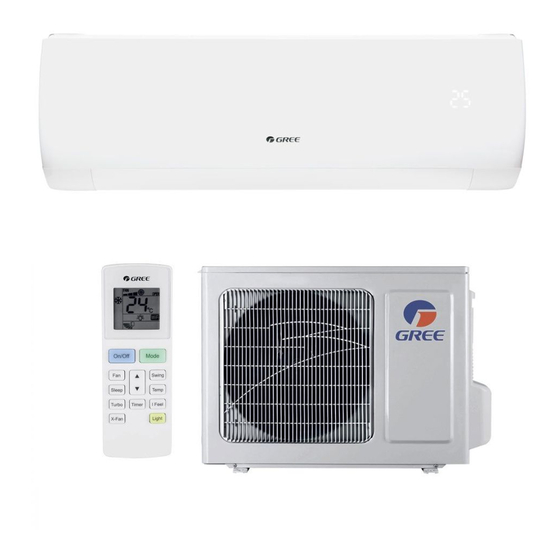
MODEL: GWH07PA-K3NNA1A
GWH09PA-K3NNA1A
GWH12PB-K3NNA1A
(Refrigerant R410A)
GREE ELECTRIC APPLIANCES,INC.OF ZHUHAI
Previous
Page
Next
Page
1
2
3
4
5
Advertisement
Need help?
Do you have a question about the GWH07PA-K3NNA1A and is the answer not in the manual?
Ask a question
Questions and answers
Related Manuals for Gree GWH07PA-K3NNA1A
Air Conditioner Gree GWH07PA-K3NNA1A Service Manual
(50 pages)
Air Handlers Gree GUD24AH2/A-D Owner's Manual
(31 pages)
Air Handlers Gree MULTI18HP230V1EO Service Manual
(89 pages)
Air Handlers Gree FLEXX Series Installation & Owner's Manual
Indoor unit (29 pages)
Air Handlers Gree GVH24AK-K3DNC6A Service Manual
(85 pages)
Air Handlers Gree FP-22LM/D-K Service Manual
Exposed fan coil unit (152 pages)
Air Handlers Gree FLEXX36HP230V1BH Installation & Owner's Manual
(32 pages)
Air Handlers Gree FLEXX ULTRA FXU24HP230V1R32AH Owner's Manual
(49 pages)
Air Handlers Gree GFH(09)CA-K6DNA1B/I Service Manual
(55 pages)
Air Handlers Gree GUD36A/A-D(U) Owner's Manual
(31 pages)
Air Handlers Gree GKH09DA-K6DNA1A/I Service Manual
(48 pages)
Air Handlers Gree UNIX GUD24A/A-D User Manual
(8 pages)
Air Handlers Gree FLEXX ECO R32 FXE24HP230V1R32AH Owner's Manual
Indoor unit (51 pages)
Air Handlers Gree U-MATCH Series Service Manual
(28 pages)
Air Handlers Gree Svalbard Extreme GWH09YD-S6DBA2A/I Service Manual
(87 pages)
This manual is also suitable for:
Gwh09pa-k3nna1a
Gwh12pb-k3nna1a
Gwh07pa-k3nna1a/i
Gwh09pa-k3nna1a/i
Gwh12pb-k3nna1a/i
Gwh07na-k3nnb1a/o
...
Show all
Gwh09na-k3nnb1c/o
Gwh12nb-k3nnb1c/o
Ca414n00500
Ca414n00501
Ca414n00600
Ca414n00601
Ca414n00700
Ca414n00701
Ca414000500
Ca414000501
Ca414000600
Ca414000601
Ca414000700
Ca414000701
Gwh07na-k3nnb1a/0
Print
Rename the bookmark
Delete bookmark?
Delete from my manuals?
Login
Sign In
OR
Sign in with Facebook
Sign in with Google
Upload manual
Upload from disk
Upload from URL


Need help?
Do you have a question about the GWH07PA-K3NNA1A and is the answer not in the manual?
Questions and answers