Advertisement
Quick Links
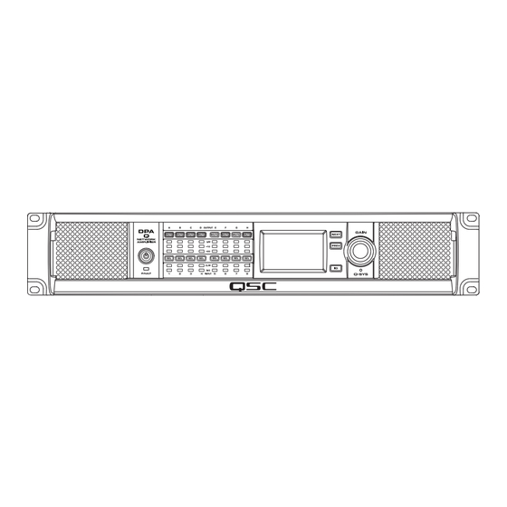
DPA-Q Series Amplifiers
®
User Manual
DPA8.4Q — 8 Channel, 4000 W Network Amplifier with Mic/Line Inputs
DPA8.8Q — 8 Channel, 8000 W Network Amplifier with Mic/Line Inputs
DPA8.4Qn — 8 Channel, 4000 W Network Amplifier
DPA8.8Qn — 8 Channel, 8000 W Network Amplifier
TD-001523-01-A
*TD-001523-01*
Advertisement

Related Manuals for QSC DPA8.8Qn


Summary of Contents for QSC DPA8.8Qn
- Page 1 DPA8.4Q — 8 Channel, 4000 W Network Amplifier with Mic/Line Inputs DPA8.8Q — 8 Channel, 8000 W Network Amplifier with Mic/Line Inputs DPA8.4Qn — 8 Channel, 4000 W Network Amplifier DPA8.8Qn — 8 Channel, 8000 W Network Amplifier TD-001523-01-A *TD-001523-01*...
- Page 2 EXPLANATION OF SYMBOLS The term “WARNING!” indicates instructions regarding personal safety. If the instructions are not followed the result may be bodily injury or death. The term “CAUTION!” indicates instructions regarding possible damage to physical equipment. If these instructions are not followed, it may result in damage to the equipment that may not be covered under the warranty.
- Page 3 The QSC DPA8.4Q, DPA8.4Qn, DPA8.8Q and DPA8.8Qn amplifiers are in compliance with European Directive 2011/65/EU – Restriction of Hazardous Substances (RoHS2). The QSC DPA8.4Q, DPA8.4Qn, DPA8.8Q and DPA8.8Qn amplifiers are in compliance with “China RoHS” directives. The following chart is provided for product use in China and its territories: QSC DPA8.4Q, DPA8.4Qn, DPA8.8Q and DPA8.8Qn Amplifiers...
- Page 4 Refer to "Amplifier Controls and Indicators" on page 8. Amplifier Rear Panel Refer to Figure 1 (DPA8.4Q / DPA8.8Q shown) NOTE!: The DPA8.4Qn and DPA8.8Qn models do not have the analog inputs (Item 3 below). — Figure 1 — RJ-45 Q-SYS Q-LAN A/B...
- Page 5 Inputs Connect the amplifier LAN A, and if available, LAN B, to the Q-LAN network (Figure 4). Refer to your Q-SYS documentation for network requirements and connection detail. Balanced Unbalanced — — — Figure 2 — — Figure 3 — —...
- Page 6 Separate Channels (A B C D) and (E F G H) For Separate Loudspeakers OUTPUTS TO SPEAKERS OUTPUTS TO SPEAKERS Use eight 2-wire cables, connect to: • T1+/T2- (Loudspeaker A / E) • T3+/T4- (Loudspeaker B / F) CH D CH E •...
- Page 7 Parallel Channels (ABCD) and (E F G H) For One Loudspeaker OUTPUTS TO SPEAKERS OUTPUTS TO SPEAKERS Full power to one loudspeaker; Use one 2-wire cable, connect to: • T3+/T4- (Loudspeaker ABCD) For Multiple Loudspeakers CH D CH E Full power for multiple loudspeakers in parallel Use up to four 2-wire cables, connect to: CH C CH F...
- Page 8 Amplifier Controls and Indicators — Figure 12 — Output Channel labels A, B, C, D, E, F, G, H Front-panel Power Button (Green/Red) 12. LCD Graphic Display Output Channel Mute Buttons / LEDs (Red) Output Channel Select Buttons / LEDs (Blue) 13.
- Page 9 Q-SYS Designer Properties menu for the amplifier. When the amplifier's configuration is changed, all of the outputs are placed in a "mute all" state. You must un-mute all in the Amp Output component's control panel or on the amplifier's front panel. DPA8.4Qn and DPA8.8Qn Refer to Figure 14 The DPA-Qn model amplifiers have no analog inputs.
- Page 10 Screens Channel Configuration Screens Figure 15 is a graphic representation of the amplifier's output CHANNEL CHANNEL CONFIGURATION CONFIGURATION. Inputs (Q) are from Q-SYS, outputs A–D (E–H not shown) represent the amplifier channels and their configuration. Text indicating how many channels, and the output configuration. For possible configurations refer to the Q-SYS help for the amplifier components.
- Page 11 LAN A / LAN B Screen LAN A (AUTO) Refer to Figure 18 IP ADDRESS: 192.168.xxx.xxx NETMASK: 255.255.0.0 IP ADDRESS – a default address is assigned in the factory. You can change this GATEWAY: and the other parameters in Q-SYS Configurator. LAN A is required, and cannot be LAN B (AUTO, NO LINK) turned off.
- Page 12 OUTPUT Screens OUTPUT Each group of outputs has a dedicated screen. Figure 21 is an example of Outputs A – D. PROTECT LIMIT SHORT 43.05ºC Output channel identifiers A – D and E – H (not shown). PROTECT LIMIT SHORT 42.16ºC DAC – when illuminated, this indicates that the signal to the D to A Converter is larger than can be reproduced and a limiter has been engaged to prevent clipping.
- Page 13 GPIO There are 16 General Purpose Input Output pins for use in various applications. Figure 22 shows the pin configuration for the connector on the rear of the amplifier. Table 1 shows the connector pin-out. Figure 23 gives some simple GPIO applications. —...
- Page 14 Specifications DPA8.4Q / DPA8.4Qn DPA8.8Q / DPA8.8Qn Max Power Continuous Max Power Continuous Channel Configuration 70 V 500 W 300 W 850 W 600 W 100 V 500 W 300 W 850 W 600 W 8 Independent Channels 8Ω 500 W...
- Page 15 DPA8.4Q / DPA8.4Qn DPA8.8Q / DPA8.8Qn Weight, net / shipping 25 lb (11.3 kg) / 29 lb (13.2 kg) 26 lb (11.8 kg) / 30 lb (13.6 kg) Dimensions (HWD) 3.5” x 19” x 16” (89mm x 482mm x 406mm) Agency approvals UL •...
- Page 16 4Ω 2Ω BTU/hr kcal/hr Amperes BTU/hr kcal/hr Amperes BTU/hr kcal/hr Amperes BTU/hr kcal/hr Amperes Idle DPA8.4Q / DPA8.4Qn DPA8.8Q / DPA8.8Qn 1/8th Power DPA8.4Q / DPA8.4Qn 1132 1399 DPA8.8Q / DPA8.8Qn 1273 10.8 1277 11.0 1457 1/3rd Power DPA8.4Q / DPA8.4Qn 1447 13.1...
- Page 17 FAX: +1.714.754.6173 © 2017 QSC, LLC. All rights reserved. QSC the QSC logo, and the Q-SYS logo are registered trademarks of QSC , LLC in the U.S. Patent and Trademark office and other countries. All other trademarks are the property of their respective owners.
Need help?
Do you have a question about the DPA8.8Qn and is the answer not in the manual?
Questions and answers