
Related Manuals for Fronius FlexTrack 45 PRO


Summary of Contents for Fronius FlexTrack 45 PRO
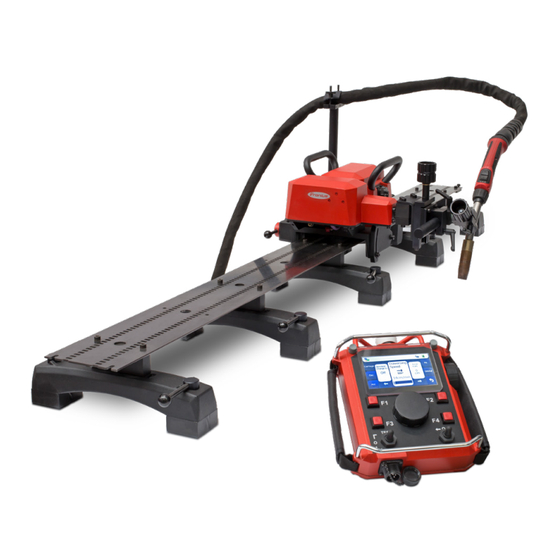
- Page 1 / Perfect Welding / Solar Energy / Perfect Charging Operating Instructions FlexTrack 45 PRO Spare Parts List Carriage 42,0426,0320,EN V12-14022023...
- Page 3 FlexTrack 45 Pro configurations ........................17 FlexTrack 45 Pro carriage configuration ....................17 FlexTrack 45 Pro rail configuration ......................18 FlexTrack 45 Pro ring rail configuration ....................18 Ring rail configuration according to work piece diameter ................. 19 Carriage components ............................ 20 Structure of the carriage ...........................
- Page 4 Preparing and installing guide rails ....................... 38 Fittings ..............................38 Number of bridges required ........................38 Bridge types ............................. 39 Installing the bridges ..........................40 Straight guide rails ........................... 41 Installing the actuating cams ........................41 Securing the rail structure ........................42 Rigid ring segments ..........................
- Page 5 Maintenance personnel ..........................99 Maintenance record ..........................99 Recommended lubricants ........................99 Maintenance intervals and procedures ....................100 Adjusting the gear rack play ........................103 Technical data Technical data ............................. 106 FlexTrack 45 PRO Carriage ........................106 Control box ............................. 106...
- Page 6 FRC-45 Basic and FRC-45 Pro ......................106 Linear oscillation unit ..........................106 Radial oscillation unit ..........................106 FMS 100/ML15/SE/ACC (optional) ......................107 F MS 50/ML15/SE/ACC (optional) ......................107 Environmental conditions ........................107 Noise data .............................. 107 Dimensions............................. 108 FMS slide dimensions ..........................109 Weights of rails and bridges ........................
- Page 7 General information...
- Page 9 Copyright Copyright of these Operating Instructions remains with Fronius International GmbH. Text and illustrations were accurate at the time of printing. Fronius reserves the right to make changes. The contents of the Operating Instructions shall not provide the basis for any claims whatsoever on the part of the purchaser.
- Page 11 Safety...
- Page 13 Carrying out all maintenance work at the specified maintenance intervals Keeping a service book with the necessary information (date, operator, activities car- ried out, etc.) Using the spare parts stipulated by Fronius Following all the instructions, particularly the safety instructions, in the Operating Instructions Using this document in conjunction with the Operating Instructions for the integrated system components (power source, etc.)
- Page 14 Spare parts, Using spare parts and wearing parts from third-party manufacturers may pose risks. Use wearing parts approved Fronius original spare parts only. and auxiliary The manufacturer cannot accept any liability for damage resulting from the use of spare materials or wearing parts or auxiliary materials that are not approved by the manufacturer.
- Page 15 Description of the carriage...
- Page 17 FlexTrack 45 Pro configurations FlexTrack 45 Pro carriage configuration FlexTrack 45 Pro carriage, including: Control box with mains cable, (3 m) Control box connection cable (10 m) Power source connection cable, 9-pin plug (10 m) Torch hosepack holder Transport box...
- Page 18 Magnetic bridge with two manually operated permanent magnets Vacuum bridge with two suction cups Eye bolt incl. locknut for securing load Rail connector for the stable connection of straight rails FlexTrack 45 Pro ring rail configuration Ø200-840mm Ø 1560 - 6060 mm Ø 840 - 1380mm Ø...
- Page 19 Ring rail configuration according to work piece diameter Ø 254 - 1320,8 mm Ø 10 - 52 in Ring rail Magnetic bridge Spring holder...
- Page 20 Carriage components Structure of the carriage Torch adjustment unit Carrying handle Linear oscillation unit* Torch holder Carrying handle Limit switch Coupling Actuating cam Locking lever Guide rollers Hosepack holder Rail Magnetic bridge * The radial oscillation unit or the FGU 8 adjustment unit can also be fitted as an option. Remote controls FRC-45 Basic FRC-45 Pro...
- Page 21 Options and accessories The radial oscillation unit can be mounted Radial oscillation on the left or the right of the carriage. unit Item no.: 8,045,590 FMS slide The FMS slide is available in two versions: FMS 100/ML15/SE/ACC Item no. 8,045,599 FMS 50/ML15/SE/ACC Item no.
- Page 22 Mechanical seam tracking Angle bracket Guide roll (side) Guide roll (height) The mechanical seam tracking can be used with a linear oscillation unit as well as with the FGU 8 adjustment unit. Use with linear oscillation unit: mount above additional FGU 9 adjustment unit; linear oscillation unit serves as an adjustment slide.
- Page 23 Controls and connections Connections Control box Control box mains cable Connection for control line between carriage and control box Connection for connection cable between control box and power source 2 with CAN communication Connection for control line between control box and remote control Connection for connection cable between control box and power source 1 with CAN communication Connection for the connection cable between the control box and power source...
- Page 24 Control box ON/OFF switch control elements Switches the control box on and off Connections Carriage Connection for linear oscillation unit Connection for FMS 50 or FMS 100, or radial oscillation unit Connection for control line between carriage and control box...
- Page 25 Carriage control elements Coupling on/off Locks/unlocks the carriage drive unit on the rail. Allows rapid positioning of the carriage. Guide rollers locking lever Fixes and releases the internal guide rollers. Limit switch (both sides, in and against direction of travel) For automatic stopping or changing of direction.
- Page 26 Welding position and weld seam tracking Welding NOTICE! positions In vertical applications, the rail structure must be secured by a load arrestor with a lock- ing function to prevent it from falling. The load arrestor must be designed for the total weight of the carriage and rail structure.
- Page 27 Welding Overhead position positions The carriage is NOT suitable for (continued) the PE and PD positions (overhead / horizontal-overhead). Use in this manner shall be deemed improper! Oscillating Linear oscillation unit Radial oscillation unit motion None Rectangular None Rectangular Oscillating motion Oscillating motion Trapezoidal Triangular...
- Page 29 Commissioning...
- Page 31 Preparing the carriage Mounting the Mounting the carriage with a linear oscillation unit: carriage with a Connect the oscillation unit to the carriage using the six screws supplied. linear oscillation Connect the connecting lead for the oscillation unit to the carriage and lock it in unit place.
- Page 32 Mounting the Mounting the carriage with a linear oscillation unit and FMS slide: carriage with a Push the torch holder onto the oscillation unit. linear oscillation Tighten the screws. unit and FMS slide Secure the FMS slide on the torch holder and close the clamping lever. Connect the connection cable for the FMS slide to the carriage.
- Page 33 Mounting the Establish the connections: see diagram below. carriage with a linear oscillation unit and FMS slide Power source (continued) Connection cable CANopen Control box mains cable Control box Connection cable linear Carriage FlexTrack 45 Connection cable Remote control Connection cable FMS Remote control Replacing Replacing the linear oscillation unit with an adjustment unit:...
- Page 34 Assembly of Mounting the FMS slide on the adjustment unit: FMS slide on the Position the FMS slide on the adjustment unit and close the clamping lever. adjustment unit Attach the torch holder to the FMS slide and close the clamping lever. Plug the FMS connection cable into the oscillation unit socket.
- Page 35 Mounting the radial oscillation unit Mounting the radial oscillation unit onto the adjustment unit: Mount the adjustment unit as described under "Replacing oscillation unit with adjustment unit" Push the vertical bolt into the horizontal holder and secure using the clamping lever.
- Page 36 Mounting the Mounting the mechanical seam tracking onto the linear oscillation unit: mechanical seam Mount the FGU 9 adjustment unit onto the linear oscillation unit. tracking Fit the mechanical seam tracking adjustable bracket to the FGU 9 adjustment unit using the four screws. Mounting the mechanical seam tracking onto the adjustment unit: Remove the plate using the clamping lever.
- Page 37 Mounting the Fit the mechanical seam tracking adjustable bracket to the FGU 8 adjustment unit mechanical seam using the four screws. tracking (continued)
- Page 38 Preparing and installing guide rails Fittings Connection pieces: Two connection pieces to extend the rails are included with every rail. Actuating cam installation kit: Two actuating cams to trigger the limit switch at the beginning and end of the guide rail. NOTICE! If actuating cams are not used, there is a risk that the carriage might travel beyond...
- Page 39 Bridge types For ring segments with a fixed radius MAGNETIC BRIDGE SPRING SUPPORT Magnetic bridges for ring segments with a Spring pressure spacer for ring segments fixed radius for mounting on ferritic com- with a fixed radius. ponents. Can also be used with non-ferritic compo- Height adjustment: 10 mm (0.39 inch).
- Page 40 Installing the Bridge without spacer and adjustment unit: bridges Fit the rail to the bridge using the two M6x65 screws and counter them using the two M6 nuts. IMPORTANT! The mounting positions for the bridges are marked: in the middle of the rail there is a recess for the adjustment unit adjusting screw.
- Page 41 Straight guide Both rigid and flexible straight guide rails can easily be extended using the joining ele- rails ments supplied. Set the levers on the magnetic bridges (1) to OFF. Place the rail section on the workpiece and set the levers on the magnetic bridges to ON.
- Page 42 Securing the rail IMPORTANT! In vertical applications, the rail structure must be secured by a load arres- structure tor with a locking function to prevent it from falling. The load arrestor must be designed for the total weight of the carriage and rail structure. The manufacturer accepts no liability for any damage to persons or property resulting from vertical use of the carriage without a load arrestor.
- Page 43 Rigid ring 3. Engage the upper locking hook (d). 4. If necessary, align the two segments segments with one another. (continued) Tighten all the M6 screws (4 at the top, 2 at the bottom). Mounting on the It is recommended that two people should work together when installing a ring rail component made from rail segments.
- Page 44 Flexible ring Flexible ring segments can be joined to create ring rails with a diameter of 1560 mm to segments 6060 mm (up to 11 segments). The individual segments are joined to form a ring rail using M6x20 socket screws. Flexible segments are available in the following lengths: SEGMENT LENGTH...
- Page 45 Ring segments The number of bridges required can be found in the following table: with a defined radius Spring pressure Diameter Magnetic bridges (continued) spacer 254,0 mm (10 in) 304,8 mm (12 in) 355,6 mm (14 in) 406,4 mm (16 in) 457,2 mm (18 in) 508,0 mm (20 in) 558,8 mm (22 in)
- Page 46 Vacuum rails Vacuum line shut-off valve - operating elements Vacuum suction cup shut-off valves Vacuum pump connection...
- Page 47 IMPORTANT! At least two persons are required to install the rail system. Mounting vacuum rails Make sure that the shut-off valve for the vacuum line is closed. Shut-off valve closed Shut-off valve open Close the shut-off valves of the vac- uum cups.
- Page 48 Mounting Connect the vacuum pump (a) to SEGMENT 1 vacuum rails the first rail segment and switch on. (continued) Place the rail segment on the part. Open the shut-off valves of the suc- tion feet one after the other in the numbered sequence (1 to 4).
- Page 49 Mounting Connect the rail segments with the vacuum rails connecting elements. (continued) Connect the vacuum line. 10. Hook the load arrestor into the eye bolts on the first and last vacuum bridge of the rail segment just mounted. 11. Open the shut-off valve of the vacu- um line on rail segment 1.
- Page 50 Mounting 12. Open the shut-off valves of the vacuum rails suction feet on rail segment 2 in the (continued) numbered sequence (1 to 4). 13. To install each additional rail seg- ment, repeat points 7 to 12.
- Page 51 Securing vacuum IMPORTANT! A failure of the vacuum pump or improper handling of the rails vacuum equipment can cause the trolley and rail construction to fall.* For this reason, the rail construction must be secured against falling during vertical use by means of a load arrestor with blocking function. The load arrestor must be designed for the total weight of the trolley and rail construction.
- Page 52 Removing IMPORTANT! At least two persons are required to remove the rail system. vacuum rails Loosen the connection screws between the penultimate and last rail segment. Hold the last rail segment in place. Close the shut-off valve of the vacuum line on the penultimate rail segment.
- Page 53 Commissioning the carriage Placing the Remove the remote control. The carriage must be installed on the carriage on a guide rail without the remote control. straight guide rail Set the mains switch on the control box to ON. Coupling and levers for the rollers in the "OFF" position. Lift the carriage using the handles and place it on the rails.
- Page 54 Placing the Tighten the three M6 mounting screws on both sides. carriage on a Manually pull the carriage along the full length of the rail once to check whether circular guide rail the welding torch remains at a constant distance from the workpiece. If the dis- (continued) tance is not constant, set the correct distance "M"...
- Page 55 Setting the The mounting plate (a) for the guide rollers has five holes in which the rollers can be mechanical seam placed and secured. tracking The rollers can be secured in these holes using the fixing screws (b). (if used) Undo the fixing screws (b) for the chosen holes.
- Page 56 Operation...
- Page 58 Connecting to the TPS power source Configuration 38,0100,0457 Connection cable between CanOpen and control box, 5 m 4,100,251 RI MOD/i CC CANopen CANopen DIP switch Image modes 8 7 6 5 4 3 2 1 Configuration - Standard image 320 bit - Economy image 128 bit - Retrofit: Scope depends on the bus module - Not used...
- Page 59 Connecting to the TPSi power source Configuration 38,0100,0463 Data cable between control box and power source, 2 m 4,044,014,IK RI FB Inside/i - Factory installation 4,044,014,CK RI FB Inside/i - Customer installation 41,0018,0081 RI MOD/i CC CANopen CANopen DIP switch Image modes 8 7 6 5 4 3 2 1 Configuration - Standard image 320 bit...
- Page 60 Setting the NODE NODE address = 6 DIP switch address: Remote (including Retrofit mode) 1 2 3 4 5 6 7 8 Node ad- control dress 1 2 3 4 5 6 7 8 Starting Switch on the TPS power source. sequence Wait until the power source is fully powered up.
- Page 61 FRC-45 Basic remote control Safety WARNING! Operating the equipment incorrectly can cause serious injury and damage. Do not use the functions described here until you have fully read and understood the following documents: These Operating Instructions All the Operating Instructions for the system components, especially the safety rules.
- Page 62 FRC-45 Basic Numerical display, 4 digits (metric / imperial) control elements Displays welding parameters and error codes. (continued) Limit switch function, change direction / stop Depending on the switch position, the welding carriage changes direction or stops as soon as the limit switch is activated. (3a) Dwell time, left / return travel path White symbol: Oscillation dwell time, left Regulates the oscillation dwell time on the left.
- Page 63 FRC-45 Basic Yellow marking: Preset segment welding control elements Preset to select the additional segment welding functions (yellow symbols). (continued) IMPORTANT! The welding process cannot start until the oscillation mode adjust- ing knob (9) is set to one of the white function parameters. Green marking: Preset path measurement Preset to select the additional path measurement function (green symbol) on the oscillation path button (10).
- Page 64 Define To set a parameter, turn the corresponding adjusting knob: parameters for to the right: to increase the value the carriage to the left: to reduce the value (continued) When a setting has been adjusted, the value of the parameter is shown on the display. Press the adjusting knob to save the value for the setting.
- Page 65 Selecting 3. Turn the knob back to the white function parameter required. additional functions (continued) Saving a program Before saving a program: Set the toggle switch for the "Change direction/stop" limit switch functions to the lower position (change direction). Set the welding mode toggle switch to the 0 position. TEST Set the traversing direction toggle switch to the central position 0.
- Page 66 Loading the NOTICE! welding program The remote control has a factory-saved, read-only program “mem0”, which contains the working parameters for the welding carriage and oscillation unit. The value “mem0” cannot be overwritten. To load a saved program, "mem" and the number of the last used program must be shown on the display.
- Page 67 Changing the Measurements can be displayed in either metric (cm) or imperial (inch) units. units of To change the units, proceed as follows: measurement Set the main switch on the control box to 0 (off). Press and hold the left and right dwell time buttons at the same time.
- Page 68 FRC-45 Pro remote control Safety WARNING! Operating the equipment incorrectly can cause serious injury and damage. Do not use the functions described here until you have fully read and understood the following documents: These Operating Instructions All the Operating Instructions for the system components, especially the safety rules.
- Page 69 FRC-45 Pro Touch display control elements Displays welding parameters and error codes. (continued) Quick Stop Stops all movement stops arc and welding process but the power supply remains present. Welding power selection wheel For regulating the preset welding power (m/min). ►...
- Page 70 Touch display SERVICE menu For loading and saving welding programs. The keys F1 to F4 are also individually assigned in the service menu. CARRIAGE menu For editing the parameters that affect the carriage. OSC menu For editing the oscillation parameters. ACC menu For editing all parameters for the ACC function (Arc Current Control).
- Page 71 Standard software functions Selecting a menu Tap the desired menu button to access the menu. The following menus are available for selection: Carriage Oscillation unit (Osc) Power source (Ps) Orbital Select a welding Three parameters are always displayed at parameter the same time.
- Page 72 Editing Rough adjustment of the parameter value: parameters Tap the slider and move (continued) as desired. Fine adjustment of the parameter value: Tap the blue arrows and set the desired value. Saving To save the adjusted value either: parameters Tap the parameter field again Press once on the multifunctional dial NOTICE! In order to edit the oscillation parameters, the oscillation unit must be attached to the...
- Page 73 Service menu Assigning Keys F1 to F4 can be assigned with functions from the service menu. function keys Follow these steps: Tap the gear wheel symbol ► The service menu will open. Use the multifunctional dial to select the "Button F1 Function" parameter field.
- Page 74 Selecting power Tap the gear wheel symbol source ► The service menu will open. Use the multifunctional dial to select the "SELECT PS" parameter field. Press the multifunctional dial once to access the list of programs. The slider appears. To select power source: either turn the multifunctional dial or touch the slider and move it.
- Page 75 Loading welding Tap the gear wheel symbol program ► The service menu will open. Use the multifunctional dial to select the "Load Program" parameter field. Press the multifunctional dial once to access the list of programs. Turn the multifunctional dial and select the desired program number.
- Page 76 Saving welding Tap the gear wheel symbol program ► The service menu will open. Use the multifunctional dial to select the "Save Program" parameter field. Press the multifunctional dial once. ► The next free program number is displayed. Press the multifunctional dial once to save the welding program.
- Page 77 Selecting the Use the multifunctional dial to select language the "Select Language" parameter (continued) field. Press the multifunctional dial once. ► The language line is displayed in blue. A blue slider appears. Use the multifunctional dial to select the required language. Press the multifunctional dial once to confirm.
- Page 78 Changing the Measurements can be displayed in either metric (cm) or imperial (inch) units. units of To change the units, proceed as follows: measurement Tap the gear wheel symbol ► The service menu will open. Use the multifunctional dial to select the "Select Units"...
- Page 79 Menu description CARRIAGE menu Press the CARRIAGE menu button to access these parameters. The following parameters are available: Travel Speed Regulates the travel speed of the welding carriage. Display in [cm/min]. Total Path Total welding path in [cm]. Once this distance has been reached, the welding process will stop automatically.
- Page 80 OSC menu Press the OSC menu button to access these parameters. The following parameters are available: Oscillation Speed Regulates the oscillation speed. When using the linear oscillation unit: Display in [cm/min] When using the radial oscillation unit: Display in [%] Oscillation Path Regulates the oscillation path.
- Page 81 PS menu (Power Press the PS menu button to access these Source) parameters. The following parameters are available: Wire feed speed Wire feed speed in m/min Gas Test To check the gas flow before starting a welding process. Wire Inching Feeds the wire Wire Retract Retracts the wire...
- Page 82 The FMS 100 or FMS 50 slide with ACC function communicates with the power source's system interface and controls the exact torch distance from the workpiece. The Fronius CANOpen i-kit, item number 4,100,251, is also required. IMPORTANT! The FMS slide with ACC function can be used with the TPS and TPSi power sources.
- Page 83 Activating the Tap the ACC menu button on the ACC function: touchscreen. FRC-45 Pro remote control ► The ACC ACTIV ON / OFF parameter is displayed. Tap the parameter field or press the multifunctional dial once. ► The OFF parameter is dis- played in blue.
- Page 84 ACC parameter FRC-45 Basic FRC-45 Pro ON / OFF FRC-45 For activating / deactivating the ACC function. S / Sensitivity FRC-45 This parameter indicates the sensitivity of the ACC function. The pre-set standard value is 5. The values are adjustable from 1 to 9. The smaller the value, the more sensitive and the quicker the reaction.
- Page 85 ORBITAL function General ORBITAL mode is used to set the parameters for welding a pipe. The Fronius CANOpen i-kit, item number 4,100,251, is also required. Activating Turn the selector switch on the remote ORBITAL control to the ORBITAL position. function:...
- Page 86 Activating Tap the ORBITAL menu button on ORBITAL the touchscreen. function: FRC-45 Pro remote control ► The ORBITAL ACTIV ON / OFF parameter is displayed. Tap the parameter field or press the multifunctional dial once. ► The OFF parameter is dis- played in blue.
- Page 87 Orbital FRC-45 Basic FRC-45 Pro parameters ON / OFF FRC-45 For activating / deactivating the ORBITAL function. Actual Position (position of the carriage) FRC-45 27° Displays the position of the carriage in relation to the current workpiece. The display ranges from 0° to 360°. This parameter is only for informational purposes and cannot be altered.
- Page 88 Orbital FRC-45 Basic FRC-45 Pro parameters A / Total Path (continued) FRC-45 A400 Shows the entire welding path in degrees. The maximum value is 900°, which is equal to 2.5 journeys around the workpiece.
- Page 89 Segment The segment welding function is for welding a round workpiece in up to 16 different seg- parameters ments. That means that the total welding path A is divided into segments. IMPORTANT! The following three steps always refer to a single segment. In the example shown, a segment is welded from 0°...
- Page 90 Starting welding: FRC-45 Basic Switching WARNING! on system Danger of injury from premature arc ignition. components The arc may be ignited accidentally. This can cause serious eye injuries. Before switching on the system components, ensure that the “Welding mode” toggle switch on the welding carriage remote control is set to the “O”...
- Page 91 Performing a test When the carriage reaches the limit switch: If the CHANGE DIRECTION/STOP toggle switch is forwards: (continued) ► The carriage stops when it triggers the limit switch. If the toggle switch is in the CHANGE DIRECTION position: ► After triggering the limit switch, only the oscillation unit stops, and the welding carriage starts to move back in the opposite direction.
- Page 92 Starting welding: FRC-45 Pro Switching WARNING! on system Danger of injury from premature arc ignition. components The arc may be ignited accidentally. This can cause serious eye injuries. Before switching on the system components, ensure that the “Welding mode” toggle switch on the welding carriage remote control is set to the “O”...
- Page 93 Starting the Set the WELDING MODE toggle switch to the "I" position. welding process Set the TRAVERSING DIRECTION toggle switch to the position required (forwards or backwards). The welding process starts. IMPORTANT! Never leave the device unattended during the weld- ing process.
- Page 94 Maintenance and disposal...
- Page 96 Troubleshooting General In the event of faults, note that the functioning of the entire system depends on many additional components (power source, wirefeeder, etc.) that are also potential sources of problems. If an error occurs, "Err" and the error number are shown on the display. Basic ►...
- Page 97 Communication error between Error 4 remote control and control box. err5 Error while saving or reading, Contact your FRONIUS service Error 5 memory error on the remote con- technician. trol. err6 Operating temperature exceeded Allow device to cool down. Operate Error 6 or ambient temperature too high.
- Page 98 Error codes Display Description Remedy (continued) Err 10 Error while the display is starting Contact your FRONIUS service Error 10 technician. Err 11 Communication error between ACC Check connections; if necessary, Error 11 module and remote control. tighten screw fittings.
- Page 99 Maintenance Maintenance WARNING! personnel Risk of injury and damage from incorrectly performed maintenance work. It is essential to adhere to the maintenance intervals and maintenance procedures. The manufacturer accepts no liability for any damage caused by inadequate or poorly performed maintenance. All maintenance work on the welding carriage must be carried out by trained techni- cians.
- Page 100 Maintenance NOTICE! intervals and Use a dry cleaning cloth to clean the machine components. Only use a cleaning agent procedures if this is indicated in the maintenance procedure for a specific part. Item Component Measure Interval Linear guides Clean, check oil film Gearbox Clean, regrease Rack and pinion...
- Page 101 Maintenance intervals and procedures (continued) Clean and lubricate the gearbox wheel: IMPORTANT! The gearbox must be cleaned and lubricated once a month (B): Clean the gear wheel with a brush Lubricate with grease Maintain the bottom of the carriage: Clean the guide rollers (D)
- Page 102 Maintenance Maintenance on the linear oscillation unit intervals and IMPORTANT! The toothed rack on the oscillation unit must be lubricated once a procedures month. (continued) The guide rail must be lubricated every six months. (a) 4x 1. Fully extend the oscillation arm. 2.
- Page 103 Adjusting the 1. Loosen the three motor bolts gear rack play (marked in green in the image) using a 2.5 mm Allen key. IMPORTANT! Only loosen them, DO NOT unscrew them completely. 2. Move the arm of the oscillation gently forwards and backwards to find the largest gap between the gear and the gear rack.
- Page 104 Technical data...
- Page 106 Technical data FlexTrack 45 PRO Welding position PA, PB, PC, PF, PG Carriage Material thickness min. 4 mm (min. 0.15 in) Horizontal traversing speed 5 - 300 cm/min (1.96 - 118.11 in.) Vertical traversing speed 5 - 250 cm/min (1.96 - 98.42 in.)
- Page 107 FMS 100/ Max. load capacity 15 kg (33.06 lb) ML15/SE/ACC Control voltage 24 VDC (optional) Power consumption Traversing speed (automatic mode) 30 cm / min (11.8 in) Traversing speed (manual mode) max. 1 m / min (39.37 in) Travel path 0.5 - 100 mm (0.01 - 3.93 in.) Degrees of sensitivity Dwell time...
- Page 108 Dimensions Dimensions with linear oscillation unit A (with oscillation unit) 469 - 556 mm (without oscillation unit) 452 - 542 mm B (with oscillation unit) 56 - 240 mm (without oscillation unit) 80 - 263 mm C (with oscillation unit) 357 mm (without oscillation unit) 342 mm...
- Page 109 FMS slide FMS slide dimensions dimensions 124 mm (4.88 in.) 308 mm (12.13 in.) 203 mm (7.99 in.) 54 mm (2.13 in.) 111 mm (4.37 in.) 50 mm (1.97 in.) 50 mm (1.97 in.) Weights of rails Magnetic bridge 2.5 kg (5.5 lb) and bridges Vacuum bridge 1.6 kg (3.5 lb)
- Page 110 Rating plates NOTICE! The rating plates may not be removed or modified without the consent of Fronius Inter- national GmbH. Ensure that the rating plates remain legible. E-Cabinet Type: FlexTrack 45 Pro Art.No.: 48,0005,2560 www.fronius.com Art.No.: 8,045,639 www.fronius.com Froniusstraße 1 Froniusstraße 1...
- Page 111 Ring rail settings table IMPORTANT! A quick-reference summary of the settings table, showing the most important settings, can be found on the inside of the transport box lid.
- Page 112 Flexible rail segments settings table...
- Page 113 Flexible rail segments settings table (continued)
- Page 114 Spare parts, Circuit Diagram...
- Page 116 Spare parts, Using spare parts and wearing parts from third-party manufacturers may pose risks. Use wearing parts approved Fronius original spare parts only. and auxiliary The manufacturer cannot accept any liability for damage resulting from the use of spare materials or wearing parts or auxiliary materials that are not approved by the manufacturer.
- Page 117 Carriage and accessories: 8,045,639 FlexTrack 45 Pro 48,0005,2614 Control box 8,045,641 FGU 8/SD80-28 8,045,640 FOU 30/ML10 8,045,590 FOU 30/ML6/radial 8,045,581 FGU 9/SD28 8,046,044 FRC-45 Basic 8,046,043 FRC-45 Pro 8,100,224 I-kit actuating cam 8,045,599 FMS 100/ML15/SE/ACC 8,045,618 FMS 50/ML15/SE/ACC 48,0005,1752 FTH 18/D16-25...
- Page 118 Rails, bridges and ring rails for variable workpiece diameters: 48,0005,1754 Rail, straight 1884 mm (74.17 inch) incl. joining elements 48,0005,1755 Magnetic bridge /1 48,0005,1756 Rail, flexible 1130 mm (44.49 inch) incl. joining elements 48,0005,1757 Rail, flexible 1695 mm (66.73 inch) incl.
- Page 119 FlexTrack 45 Carriage Pro Item no.: 8,045,639 48,0005,2602 48,0005,2502 48,0005,2603 48,0005,2604 48,0005,2605 48,0005,2606 48,0005,2435 48,0005,2607 48,0005,2610 48,0005,2608 48,0005,1809 48,0005,2609 48,0005,1818 38,0100,0433 48,0005,2611 48,0005,1817 48,0005,2612 48,0005,2613 48,0005,2612...
- Page 120 FlexTrack 45 Carriage Pro Item no.: 8,045,639 Control box interior 48,0005,2562...
- Page 121 FRC-45 Pro remote control Item no.: 8,046,043 48,0005,2624 48,0005,2625 48,0005,2626 48,0005,2628 48,0005,2627 48,0005,2629 48,0005,2631 48,0005,2633 48,0005,2630 48,0005,2632 48,0005,2634 48,0005,2635 48,0005,2636 Not shown in drawing: Micro-SD-Card, Art. No: 48,0005,0132...
- Page 122 FRC-45 Basic remote control Item no.: 8,046,044 48,0005,2624 48,0005,1855 48,0005,0000 48,0005,1857 48,0005,1856 48,0005,2158 48,0005,2498 48,0005,2497 48,0005,2495 48,0005,0012 48,0005,0013 48,0005,2494 48,0005,2631...
- Page 123 FGU 8/SD80-28 Item no.: 8,045,641 8,045,578 48,0005,1823 FGU 9 / SD28 Item no.: 8,045,581 8,045,581...
- Page 124 FOU 30 / ML 10 / linear Item no.: 8,045,640 48,0005,2620 48,0005,2615 48,0005,2616 48,0005,2837 48,0005,1841 48,0005,2618 48,0005,2619 48,0005,2622 48,0005,2623 48,0005,2621 48,0005,1842...
- Page 125 FOU 30 / ML6 / radial Item no.: 8,045,590 48,0005,1929 48,0005,1934 48,0005,1839 48,0005,1936 48,0005,1937 48,0005,1935 48,0005,1938 48,0005,1939 48,0005,1931 48,0005,1930 48,0005,1932 48,0005,1933 48,0005,1207 48,0005,1136 48,0005,0125 48,0005,1393 48,0005,1207 48,0005,1392 48,0005,1206 48,0005,1207...
- Page 126 FMS 100/ML15/SE/ACC Item no.: 8,045,599 48,0005,2164 48,0005,2165 48,0005,2166 48,0005,2167 48,0005,2168 48,0005,2169 48,0005,2170 48,0005,2171...
- Page 127 FMS 50/ML15/SE/ACC Item no.: 8,045,618 48,0005,2164 48,0005,2557 48,0005,2166 48,0005,2167 48,0005,2558 48,0005,2559 48,0005,2170 48,0005,2171...
- Page 128 Mechanical seam tracking (no overall item number)
- Page 129 FTH 18/D16-25 Item no.: 48,0005,1752 48,0005,1752 FTH 21 Item no.: 48,0005,1777 48,0005,1777...
- Page 130 Closed ring rail 48,0005,1838 48,0005,1826 48,0005,1827 48,0005,1838 48,0005,1824 48,0005,1825 Straight guide rails (rigid and flexible) 48,0005,2508 48,0005,2506...
- Page 131 Vacuum bridge Item no. 48,0005,1771...
- Page 132 Vacuum bridge Item no. 48,0005,1771 with spacer block Item no. 48,0005, 1886...
- Page 133 Vacuum bridge Item no. 48,0005,1771 with adjustment unit Item no. 48,0005, 2083/48,0005,2085...
- Page 134 Setting gauge Drawing number: 58-1301-1100 48,0007,0274...
- Page 135 Wiring diagram...
- Page 139 STEPPER MOTOR DRIVER 496.77.04.00.0 STEPPER MOTOR blue green black CAN H CAN L 496.96.14.00.0 ARC CURRENT CONTROL...
- Page 140 STEPPER MOTOR DRIVER 496.77.04.00.0 STEPPER MOTOR blue green black CAN H CAN L 496.77.01.01.0 OSCILLATOR RADIAL...
- Page 141 Hereby certifies on its sole se déclare seule responsable du fait dass folgendes Produkt: responsibility that the following que le produit suivant: product: FlexTrack 45 PRO FlexTrack 45 PRO FlexTrack 45 PRO Fahrwerk Welding carriage Chariot de soudage auf das sich diese Erklärung which is explicitly referred to by this qui est l’objet de la présente...
- Page 149 FRONIUS INTERNATIONAL GMBH TechSupport Automation www.fronius.com www.fronius.com/addresses...
Need help?
Do you have a question about the FlexTrack 45 PRO and is the answer not in the manual?
Questions and answers