
Related Manuals for PerfecTron SR800


Summary of Contents for PerfecTron SR800
- Page 1 Version 1.1 Quick Installation Guide Revision Date: Jun.25.2019 SR800 Rugged Fanless Military Computer with Intel Xeon D-1587 processor, 24V DC-In www.perfectron.com...
- Page 2 Safety information Electrical safety To prevent electrical shock hazard, disconnect the power cable from the electrical outlet before relocating the system. When adding or removing devices to or from the system, ensure that the power cables for the devices are unplugged before the signal cables are connected. If possible, disconnect all power cables from the existing system before you add a device. Before connecting or removing signal cables from the motherboard, ensure that all power cables are unplugged. Seek professional assistance before using an adapter or extension cord. These devices could interrupt the grounding circuit. Make sure that your power supply is set to the correct voltage in your area. If you are not sure about the voltage of the electrical outlet you are using, contact your local power company. If the power supply is broken, do not try to fix it by yourself. Contact a qualified service technician or your local distributor.
- Page 3 Revision History Revision Date (yyyy/mm/dd) Changes Version 1.0 2018/10/05 Initial release Change Product photo & Status LED specification Version 1.1 2019/06/25 Packing list □ SR800 Fanless Rugged System □ CD (Driver + Quick Installation Guide) Ordering information Description Model Number SR800 Rugged Fanless military computer with Intel Xeon D‐1587 processor, 24V DC‐IN, Operating Temperature 0 to 50°C If any of the above items is damaged or missing, please contact your local distributor. ...
- Page 4 Table Contents SAFETY INFORMATION .............................. 2 ................................2 LECTRICAL SAFETY ................................ 2 PERATION SAFETY STATEMENT ................................ 2 REVISION HISTORY .............................. 3 PACKING LIST ................................3 ORDERING INFORMATION ............................ 3 TABLE CONTENTS ................................4 CHAPTER 1: PRODUCT INTRODUCTION ........................5 ................................5 EY EATURES ................................. 6 IMENSIONS ................................6 ANEL OMPONENT CHAPTER 2: JUMPERS AND CONNECTORS LOCATIONS ....................7 ..........................7 ...
- Page 5 Chapter 1: Product Introduction 1.1 Key Features System Intel® Xeon® Processor D‐1587 Processor (24M SmartCache, 16 Cores/ CPU 32 Threads, Base Frequency 1.7GHz; Max Turbo Frequency 2.30 GHz) Memory Type Supports up to 128GB DDR4 ECC RDIMM BIOS AMI® BIOS Storage Device SATA1: 2.5” SATAIII SSD 64GB SATA2: 2.5” SATAIII SSD 2TB I/O VGA 1 x DB15, resolution up to 1920x1200 1Gb Ethernet 1 x Souriau 8ST7-10G35SA connector (via Intel® i350-AM2) 100M Ethernet 1 x Souriau 8ST7-08G35SN connector (via Intel® i350-AM2) IPMI 1 x RJ45 USB 2 x USB 3.0, 1 x USB 2.0 1 x Souriau 8ST7-10G35SB connector (RS232) ...
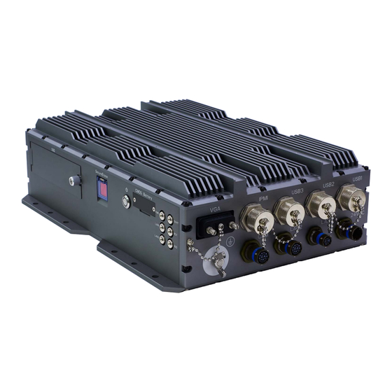
- Page 6 1.2 Dimensions 1.3 Panel Component ...
- Page 7 VGA, label (VGA) 1 IPMI, label (IPMI) 2 USB3.0, label (USB3) 3 USB3.0, label (USB2) 4 USB2.0, label (USB1) 5 6 Ground Screw COM (RS232), label (X9 COM) 7 Gigabit Ethernet, label (X5 LAN2) 8 100M Ethernet, label (X6 LAN1) 9 ...
- Page 8 COM (X9): RS232 Pin Definition Pin Definition 8 RXD 2 DCD# NC 3 DSR# 10 NC 4 CTS# 11 NC 5 12 NC 6 RTS# 13 GND CASE 7 DTR# Ethernet (X6): 100M Pin Definition 2 3 4 5 6 GND CASE Ethernet (X5): Gigabit Pin ...
- Page 9 2.2 LED Indication LED: LED Function Vehicle Power Ready PWR LAN1 LAN1 Active LED LAN2 Active LED LAN2 OVHT Overheat LED* RDY UID LED SSD SSD2 Access LED Note: LED overheat alarm if an overheat condition is detected (CPU Temperature over 105℃)
- Page 10 Chapter 3 BIOS Introduction This chapter describes the AMI BIOS setup utility for the System motherboard. The ROM BIOS is stored in a Flash EEPROM and can be easily updated. This chapter describes the basic navigation of the AMI BIOS setup utility setup screens.
- Page 11 Flashing the wrong BIOS can cause irreparable damage to the system. In no event shall Perfectron be liable for direct, indirect, special, incidental, or consequential dam-ages arising from a BIOS update. If you have to update the BIOS, do not shut down or reset the system while the BIOS is updating.
- Page 12 The following Main menu items will display: System Date/System Time Use this feature to change the system date and time. Highlight System Date or System Time using the arrow keys. Enter new values using the keyboard. Press the <Tab> key or the arrow keys to move between fields. The date must be entered in Day MM/DD/YY format.
- Page 13 Advanced Setup Con igurations Use the arrow keys to select Boot Setup and press <Enter> to access the submenu items. Warning: Take caution when changing the Advanced settings. An incorrect value, a very high DRAM frequency, or an incorrect DRAM timing setting may make the system unstable.
- Page 14 Wait For 'F1' If Error Use this feature to force the system to wait until the 'F1' key is pressed if an error occurs. The options are Disabled and Enabled. INT19 (Interrupt 19) Trap Response Interrupt 19 is the software interrupt that handles the boot disk function. When this item is set to Immediate, the ROM BIOS of the host adaptors will "capture"...
- Page 15 CPU Configuration The following CPU information will be displayed: • Processor ID • Processor Frequency • Processor Max Ratio • Processor Min Ratio • Microcode Revision • L1 Cache RAM • L2 Cache RAM • L3 Cache Ram • CPU Version Clock Spread Spectrum If this feature is set to Enabled, the BIOS utility will monitor the level of Electro-...
- Page 16 Execute Disable Bit (Available if supported by the OS & the CPU) Select Enabled to enable the Execute-Disable Bit which will allow the processor to designate areas in the system memory where an application code can execute and where it cannot, thus preventing a worm or a virus from flooding illegal codes to overwhelm the processor or damage the system during an attack.
- Page 17 Intel ® Virtualization Technology (Available when supported by the CPU) Select Enabled to support Intel ® Virtualization Technology, which will allow one platform to run multiple operating systems and applications in independent parti- tions, creating multiple "virtual" systems in one physical computer. The options are Enable and Disable.
- Page 18 Boot Performance Mode This feature allows the user to select the performance state that the BIOS will set before the operating system handoff. The options are Max Performance and Max Efficient. Turbo Mode Select Enable for processor cores to run faster than the frequency specified by the manufacturer.
- Page 19 Enhanced Halt State (C1E) Select Enabled to use Enhanced Halt-State technology, which will significantly reduce the CPU's power consumption by reducing the CPU's clock cycle and voltage during a Halt-state. The options are Disable and Enable. CPU T State Control ACPI (Advanced Configuration Power Interface) T-States Select Enable to support CPU throttling by the operating system to reduce power consumption.
- Page 20 SAPM Control This feature indicates whether the PCU should control the System Agent PM using its power-performance tuning algorithm. The options are Enable and Disable. Energy Efficient Turbo Use this feature to enable energy efficient turbo mode. The options are En- able and Disable.
- Page 21 ® IOAT (Intel IO Acceleration) Configuration Enable IOAT Select Enable to enable Intel I/OAT (I/O Acceleration Technology) support, which significantly reduces CPU overhead by leveraging CPU architectural improve- ments and freeing the system resource for other tasks. The options are Enable and Disable.
- Page 22 Data Scrambling Select Enabled to enable data scrambling to enhance system performance and data integrity. The options are Auto, Disabled and Enabled. DRAM RAPL Baseline Use this feature to set the run-time power-limit baseline for DRAM modules. The options are Disable, DRAM RAPL Mode 0, and DRAM RAPL Mode 1. Set Throttling Mode Throttling improves reliability and reduces power consumption in the processor via automatic voltage control during processor idle states.
- Page 23 Patrol Scrub Interval This feature allows you to decide how many hours the system should wait before the next complete patrol scrub is performed. Use the keyboard to enter a value from 0-24. The Default setting is 24. Demand Scrub Demand Scrubbing is a process that allows the CPU to correct correctable memory errors found on a memory module.
- Page 24 EHCI1 Select Enabled to enable EHCI (Enhanced Host Controller Interface) support on USB 2.0 connector #1 (at least one USB 2.0 connector should be enabled for EHCI support). The options are Disabled and Enabled. EHCI2 Select Enabled to enable EHCI (Enhanced Host Controller Interface) support on USB 2.0 connector #2 (at least one USB 2.0 connector should be enabled for EHCI support).
- Page 25 SATA Port 0~ Port 5 This item displays the information detected on the installed SATA drive on the particular SATA port. • Model number of drive and capacity • Software Preserve Support Port 0 ~ Port 5 Hot Plug This feature designates this port for hot plugging. Set this item to Enabled for hot-plugging support, which will allow the user to replace a SATA drive without shutting down the system.
- Page 26 • ME Firmware Status #1 • ME Firmware Status #2 • Current State • Error Code PCIe/PCI/PnP Configuration The following information will display: • PCI Bus Driver Version • PCI Devices Common Settings: PCI PERR/SERR Support Select Enabled to allow a PCI device to generate a PERR/SERR number for a PCI Bus Signal Error Event.
- Page 27 M.2 PCI-E 3.0 X4 Use this feature to select which firmware type to be loaded for the add-on card in this slot. The options are Disabled, Legacy, and EFI. SLOT 7 PCI-E 3.0 X16 Use this feature to select which firmware type to be loaded for the add-on card in this slot.
- Page 28 Serial Port Select Enabled to enable the selected onboard serial port. The options are Enabled and Disabled. Device Settings This item displays the status of a serial part specified by the user. Change Port 1 Settings This feature specifies the base I/O port address and the Interrupt Request address of a serial port specified by the user.
- Page 29 Data Bits Use this feature to set the data transmission size for Console Redirection. The options are 7 Bits and 8 Bits. Parity A parity bit can be sent along with regular data bits to detect data transmission errors. Select Even if the parity bit is set to 0, and the number of 1's in data bits is even.
- Page 30 Putty KeyPad This feature selects the settings for Function Keys and KeyPad used for Putty, which is a terminal emulator designed for the Windows OS. The options are VT100, LINUX, XTERMR6, SC0, ESCN, and VT400. Redirection After BIOS Post Use this feature to enable or disable legacy console redirection after BIOS POST. When set to Bootloader, legacy console redirection is disabled before booting the OS.
- Page 31 Parity A parity bit can be sent along with regular data bits to detect data transmission errors. Select Even if the parity bit is set to 0, and the number of 1's in data bits is even. Select Odd if the parity bit is set to 0, and the number of 1's in data bits is odd.
- Page 32 Redirection After BIOS Post Use this feature to enable or disable legacy Console Redirection after BIOS POST. When set to Bootloader, legacy Console Redirection is disabled before booting the OS. When set to Always Enable, legacy Console Redirection remains enabled when booting the OS.
- Page 33 Flow Control Use this item to set the flow control for Console Redirection to prevent data loss caused by buffer overflow. Send a "Stop" signal to stop sending data when the re- ceiving buffer is full. Send a "Start" signal to start sending data when the receiving buffer is empty.
- Page 34 Event Logs Use this feature to configure Event Log settings. Change SMBIOS Event Log Settings Enabling/Disabling Options SMBIOS Event Log Change this item to enable or disable all features of the SMBIOS Event Logging during system boot. The options are Enabled and Disabled. Runtime Error Logging Support Select Enabled to support Runtime Error Logging.
- Page 35 PCI-Ex (PCI-Express) Error Enable Select Yes for the BIOS to correct errors occurred in the PCI-E slots. The options are Yes and No. Erasing Settings Erase Event Log If No is selected, data stored in the event log will not be erased. Select Yes, Next Reset, data in the event log will be erased upon next system reboot.
- Page 36 IPMI Use this feature to configure Intelligent Platform Management Interface (IPMI) settings. BMC Firmware Revision This item indicates the IPMI firmware revision used in your system. IPMI Status (Baseboard Management Controller) This item indicates the status of the IPMI firmware installed in your system. System Event Log ...
- Page 37 When SEL is Full This feature allows the user to decide what the BIOS should do when the system event log is full. Select Erase Immediately to erase all events in the log when the system event log is full. The options are Do Nothing and Erase Immediately. Note: After making changes on a setting, be sure to reboot the system for the changes to take effect.
- Page 38 Station MAC Address This item displays the Station MAC address for this computer. Mac addresses are 6 two-digit hexadecimal numbers. Gateway IP Address This item displays the Gateway IP address for this computer. This should be in decimal and in dotted quad form (i.e., 172.31.0.1).
- Page 39 Security Settings This menu allows the user to configure the following security settings for the system. Password Check Select Setup for the system to check for a password at Setup. Select Always for the system to check for a password at bootup or upon entering the BIOS Setup utility. The options are Setup and Always.
- Page 40 Secure Boot Use this item to enable secure boot. The options are Disabled and Enabled. Secure Boot Mode Use this item to select the secure boot mode. The options are Standard and Custom. Key Management This submenu allows the user to configure the following Key Management settings. Factory Default Key Provision Select Enabled to install the default Secure-Boot keys set by the manufacturer.
- Page 41 Authorized Signatures Set New Key Select Yes to load the database from the manufacturer's defaults. Select No to load the DB from a file. The options are Yes and No. Append Key Select Yes to add the database from the manufacturer's defaults to the existing DB. Select No to load the DB from a file.
- Page 42 Boot Settings Use this feature to configure Boot Settings: Setup Prompt Timeout Use this item to indicate the length of time (the number of seconds) for the BIOS to wait before rebooting the system when the setup activation key is pressed. Enter the value of 65535 (0xFFFF) for the BIOS to wait indefinitely.
- Page 43 • Boot Option #6 • Boot Option #7 • Boot Option #8 • Boot Option #9 • Boot Option #10 • Boot Option #11 • Boot Option #12 • Boot Option #13 • Boot Option #14 • Boot Option #15 Delete Boot Option ...
- Page 44 Save & Exit Select the Exit tab from the BIOS setup utility screen to enter the Exit BIOS Setup screen. Discard Changes and Exit Select this option to quit the BIOS Setup without making any permanent changes to the system configuration, and reboot the computer. Select Discard Changes and Exit from the Exit menu and press <Enter>.
- Page 45 Restore Defaults To set this feature, select Restore Defaults from the Save & Exit menu and press <Enter>. These are factory settings designed for maximum system stability, but not for maximum performance. Save As User Defaults To set this feature, select Save as User Defaults from the Exit menu and press <En- ter>.
- Page 46 Appendix A: POST Error Beep Codes Appendix A BIOS Error Beep Codes During the POST (Power-On Self-Test) routines, which are performed each time the system is powered on, errors may occur. Non-fatal errors are those which, in most cases, allow the system to continue with bootup.
Need help?
Do you have a question about the SR800 and is the answer not in the manual?
Questions and answers