
Related Manuals for PerfecTron SR200


Summary of Contents for PerfecTron SR200
- Page 1 Version 1.0 MIL-STD Rugged Computer Revision Date: JAN. 20, 2015 User’s Manual SR200 MIL-STD Rugged Computer User’s Manual www.perfectron.com...
-
Page 2: Safety Information
SR200 MIL-STD Rugged Computer User’s Manual V1.0 Safety information Electrical safety To prevent electrical shock hazard, disconnect the power cable from the electrical outlet before relocating the system. When adding or removing devices to or from the system, ensure that the power cables for the devices are unplugged before the signal cables are connected. -
Page 3: Revision History
SR200 MIL-STD Rugged Computer User’s Manual V1.0 Revision History Revision Date (yyyy/mm/dd) Changes V1.0 2015/01/20 Initial release Packing list □ SR200 MIL-STD Rugged Computer □ XR-DIMM up to 8 GB RAM optional Accessories Kit □ Terminal block 4 PIN x 1pcs □... -
Page 4: Table Of Contents
SR200 MIL-STD Rugged Computer User’s Manual V1.0 Table of contents SAFETY INFORMATION ............................1 ..............................1 LECTRICAL SAFETY ..............................1 PERATION SAFETY STATEMENT ................................. 1 REVISION HISTORY .............................. 2 PACKING LIST ..............................2 ACCESSORIES KIT ..............................2 ORDERING INFORMATION ........................... 2 TABLE OF CONTENTS ............................ - Page 5 SR200 MIL-STD Rugged Computer User’s Manual V1.0 3.4.2 ACPI Settings ............................17 3.4.3 CPU configuration ..........................18 3.4.4 SATA Configuration ..........................23 Software Feature Mask Configuration ..................... 25 3.4.5 Intel Rapid Start Technology ......................... 27 3.4.6 PCH-FW Configuration .......................... 27 Firmware Update Configuration .......................
-
Page 6: Chapter 1: Product Introduction
SR200 MIL-STD Rugged Computer User’s Manual V1.0 Chapter 1: Product Introduction 1.1 Key Features System Intel® Core™ i7 Haswell , BGA type Core i7-4700EQ (4C x 2.4/1.7 GHz), 6M Cache (47W) Chipset Intel® QM87 PCH Ethernet Chipset Intel® I210IT & i217-LM GbE... - Page 7 SR200 MIL-STD Rugged Computer User’s Manual V1.0 Standards and Certifications MIL-STD-810G Test Method 507.5, Procedure II (Temperature & Humidity) Method 514.6, Procedure I (Category 20 & 24, Vibration) Method 516.6, Procedure I (Mechanical Shock) Method 501.5, Procedure I (Storage/High Temperature) Method 501.5, Procedure II (Operation/High Temperature)
-
Page 8: Front Panel Components
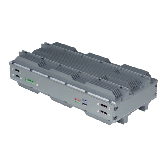
SR200 MIL-STD Rugged Computer User’s Manual V1.0 1.2 Front Panel Components 2 x USB 3.0 1 x RS232/422/485 with 5V/12V selectable LAN port, 2 x RJ45 Audio jack (1 x MIC, 1 x Line out) 1.3 Back Panel Components 2 x DisplayPort... -
Page 9: Mechanical Dimensions
SR200 MIL-STD Rugged Computer User’s Manual V1.0 1.4 Mechanical Dimensions www.perfectron.com... -
Page 10: Chapter 2: Jumpers And Connectors Locations
SR200 MIL-STD Rugged Computer User’s Manual V1.0 Jumpers and Connectors Locations Chapter 2: This chapter describes the jumpers and connectors on the systems’ motherboard. 2.1 Front Panel Connector Pin Definitions Status Indicators LED1: LAN1 LED STATUS LED1 Light Dark Flash... -
Page 11: Dp1,2,3,4: Display Port
SR200 MIL-STD Rugged Computer User’s Manual V1.0 DP1,2,3,4: DISPLAY PORT PIN DEFINITION PIN DEFINITION 1 DPC_LANEP0 2 GND 3 DPC_LANEN0 4 DPC_LANEP1 5 GND 6 DPC_LANEN1 7 DPC_LANEP2 8 GND 9 DPC_LANEN2 10 DPC_LANEP3 11 GND 12 DPC_LANEN3 13 DDIC_DDC_AUX_SEL 14 GND... -
Page 12: Usb3.0 Cn18: Usb*2
SR200 MIL-STD Rugged Computer User’s Manual V1.0 USB3.0 CN18: USB*2 LOWER USB UPPER USB PIN DEFINITION PIN DEFINITION USB_VCC0 USB_VCC1 USBD2- USBD3- USBD2+ USBD3+ USB_SSRX1N_C USB_SSRX2N_C USB_SSRX1P_C USB_SSRX2P_C USB3TN1 USB3TN2 USB3TP1 USB3TP2 MIC 1: Audio Jacks Connector PIN DEFINITION MIC_L... - Page 13 SR200 MIL-STD Rugged Computer User’s Manual V1.0 +3.3VAUX LED_WWAN# LED_WLAN# Reserved LED_WPAN# Reserved 1.5V Reserved Reserved 3.3VAUX www.perfectron.com...
-
Page 14: Chapter 3: Ami Bios Utility
SR200 MIL-STD Rugged Computer User’s Manual V1.0 Chapter 3: AMI BIOS UTILITY This chapter provides users with detailed descriptions on how to set up a basic system configuration through the AMI BIOS setup utility. 3.1 Starting To enter the setup screens, perform the following steps: •... -
Page 15: Main Menu
SR200 MIL-STD Rugged Computer User’s Manual V1.0 3.3 Main Menu The Main menu is the screen that first displays when BIOS Setup is entered, unless an error has occurred. You could setup these items on the Main menu: System Language: Choose the system default language. -
Page 16: Advanced Menu
SR200 MIL-STD Rugged Computer User’s Manual V1.0 3.4 Advanced Menu This section allows you to configure and improve your system and allows you to set up some system features according to your preference. www.perfectron.com... -
Page 17: Pci Subsystem Settings
SR200 MIL-STD Rugged Computer User’s Manual V1.0 3.4.1 PCI Subsystem Settings PCI, PCI-X and PCI Express settings. PCI Common Settings PCI Latency Timer: Value to be programed into PCI Latency Timer Register. VGA Palette Snoop: Enable or disable VGA Palette Registers Snooping. -
Page 18: Acpi Settings
SR200 MIL-STD Rugged Computer User’s Manual V1.0 Link Training Retry Defines number of retry attempts software will take to retrain the link if previous training attempt was unsuccessful. Link Training Time out (uS) Defines number of Microseconds software will wait before polling “Link training” bit in link status register. -
Page 19: Cpu Configuration
SR200 MIL-STD Rugged Computer User’s Manual V1.0 ACPI Sleep State Select ACPI sleep state the system will enter when the suspend button is pressed. Lock Legacy Resources Enable or disable lock of legacy resource. S3 Video Repost Enable or disable S3 Video Repost. - Page 20 SR200 MIL-STD Rugged Computer User’s Manual V1.0 www.perfectron.com...
- Page 21 SR200 MIL-STD Rugged Computer User’s Manual V1.0 Hyper-threading Enable for windows XP and Linux(OS optimized for Hyper-Threading Technology) and Disabled for other OS (OS not optimized for Hyper-Threading Technology). When Disabled only one thread per enabled core is enabled. Active Processor Cores Number of cores to enable in each processor package.
- Page 22 SR200 MIL-STD Rugged Computer User’s Manual V1.0 CPU AES Enable/disable CPU advanced encryption standard instruction. Boot performance mode Select the performance state that the BIOS will set before OS handoff. EIST Enable/Disable Intel speed step. Turbo Mode Enable/Disable CPU turbo mode Energy performance Optimize between performance and power savings.
- Page 23 SR200 MIL-STD Rugged Computer User’s Manual V1.0 CPU C States Enable or disable CPU C states. Enhanced C1 State: Enhanced C1 State CPU C3 Report: Enable /disable CPU C3 report to OS CPU C6 Report: Enable /disable CPU C6 report to OS...
-
Page 24: Sata Configuration
SR200 MIL-STD Rugged Computer User’s Manual V1.0 CPU DTS Disabled: ACPI thermal management uses EC reported temperature value. Enabled: ACPI thermal management uses DTS SMM mechanism to obtain CPU temperature values. Out of Spec: ACPI Thermal Management uses EC reported temperature values and DTS SMM is used to handle Out of spec. - Page 25 SR200 MIL-STD Rugged Computer User’s Manual V1.0 SATA Controller(s) Enable or disable SATA device. SATA Mode Selection Determines how SATA controller(s) operate. The options are: IDE, AHCI, RAID SATA Test Selection Enable or disable Test Mode Aggressive LPM Support Enable PCH to aggressively enter link power state.
-
Page 26: Software Feature Mask Configuration
SR200 MIL-STD Rugged Computer User’s Manual V1.0 Software Feature Mask Configuration RADI OROM/RST driver will refer to the SWFW configuration to enable or disable the storage features. RAID0: Enable or disable RAID0 feature. RAID1: Enable or disable RAID1 feature. RAID10: Enable or disable RAID10 feature. - Page 27 SR200 MIL-STD Rugged Computer User’s Manual V1.0 Serial ATA Port 2 Port 2: Enable or disable SATA port Hot Plug: Designates this port as Hot Pluggable. External SATA: External SATA support. SATA device type: Identify the SATA port is connected to Solid State Drive or Hard Disk Drive.
-
Page 28: Intel Rapid Start Technology
SR200 MIL-STD Rugged Computer User’s Manual V1.0 3.4.5 Intel Rapid Start Technology Enable or disable Intel Rapid Start Technology 3.4.6 PCH-FW Configuration Configure Management Engine Technology Parameters. MDES BIOS Status Code Enable/Disable MDES BIOS Status Code. www.perfectron.com... -
Page 29: Firmware Update Configuration
SR200 MIL-STD Rugged Computer User’s Manual V1.0 Firmware Update Configuration Configure Management Engine Technology Parameters. Me FW Image Re-Flash: Enable/Disable Me FW Image Re-Flash function. 3.4.7 Intel Anti-Theft Technology Configuration Disabling Intel AT allow user to login to platform. This is strictly for testing only. This does not disable Intel AT services in ME. -
Page 30: Amt Configuration
SR200 MIL-STD Rugged Computer User’s Manual V1.0 3.4.8 AMT Configuration Configure Active Management Technology Parameters. Intel AMT Enable/Disable Intel Active Management Technology BIOS Extension. Note: iAMT H/W is always enabled. This option just controls the BIOS extension execution. If enabled, this requires additional firmware in the SPI device. - Page 31 SR200 MIL-STD Rugged Computer User’s Manual V1.0 Disable ME Set ME to Soft Temporary Disabled. Enable/Disable Alert Specification Format. Activate Remote Assistance Process Trigger CIRA boot. USB Configure Enable/Disable USB Configure function. PET Progress User can Enable/Disable PET Events progress to receive PET events or not.
-
Page 32: Usb Configuration
SR200 MIL-STD Rugged Computer User’s Manual V1.0 3.4.9 USB Configuration USB Configuration Parameters. Legacy USB Support Enables legacy USB support. AUTO option disables legacy support if no USB devices are connected. DISABLE option will keep USB devices available only for EFI applications. -
Page 33: It8786 Super Io Configuration
SR200 MIL-STD Rugged Computer User’s Manual V1.0 USB hardware delays and time-outs: USB transfer time-out: The time-out value for Control, Bulk, and Interrupt transfers. The options are 1 sec, 5 sec, 10 sec, 20 sec. Device reset time-out: USB mass storage device Start Unit command time-out. The options are 10 sec, 20 sec, 30 sec, 40 sec. -
Page 34: Serial Port 3 Configuration
SR200 MIL-STD Rugged Computer User’s Manual V1.0 Serial Port 3 Configuration Set Parameters of Serial Port 2 (COMC). Serial Port: Enable or Disable Serial Port (COM). Device Settings: IO=3E8h, IRQ=7 Change Settings: Select an optimal setting for Super IO device. -
Page 35: It8786 Hw Monitor
SR200 MIL-STD Rugged Computer User’s Manual V1.0 3.4.11 IT8786 HW Monitor Monitor hardware status. 3.4.12 Serial Port Console Redirection Console Redirection Console Redirection Enable or Disable. www.perfectron.com... -
Page 36: Console Redirection Setting
SR200 MIL-STD Rugged Computer User’s Manual V1.0 Console Redirection Setting The Settings specify how the host computer and the remote computer will exchange data. Both computers should have the same or compatible setting. Out-of-Band Mgmt Port: Microsoft Windows Emergency Management Service allows for remote management of a Windows Server OS through a serial port. -
Page 37: Intel I210 Gigabit Network Connection
SR200 MIL-STD Rugged Computer User’s Manual V1.0 3.4.14 Intel I210 Gigabit Network Connection Configure Gigabit Ethernet device parameters. PORT CONFIGURATION MENU NIC Configuration: Configure Boot Protocol, wake on LAN, Link Speed, and VLAN. Blink LEDs: Identify the physical network port by blinking the associated LED. -
Page 38: Chipset
SR200 MIL-STD Rugged Computer User’s Manual V1.0 3.5 Chipset This section gives you functions to configure the system based on the specific features of the chipset. The chipset manages bus speeds and access to system memory resources. 3.5.1 PCH IO configuration... -
Page 39: Pci Express Configuration
SR200 MIL-STD Rugged Computer User’s Manual V1.0 PCI Express Configuration PCI Express Configuration settings PCIE Root Port Function Swapping: Enable or disable PCI Express PCI Express Root Port Function Swapping. Subtractive Decode: Enable or disable PCI Express Subtractive Decode. PCI Express Root Port1 PCI Express Root Port1 setting. -
Page 40: Pci Express Root Port2
SR200 MIL-STD Rugged Computer User’s Manual V1.0 PCI Express Root Port2 control the PCI Express Root port, the options are enabled/disabled. ASPM Support: Set the ASPM Level: Force L0s – Force all links to L0s State: AUTO – BIOS auto configure: DISABLE –... -
Page 41: Pci Express Root Port3
SR200 MIL-STD Rugged Computer User’s Manual V1.0 PCI Express Root Port3 control the PCI Express Root port, the options are enabled/disabled ASPM Support: Set the ASPM Level: Force L0s – Force all links to L0s State: AUTO – BIOS auto configure: DISABLE –... -
Page 42: Pci Port 4 Is Assigned To Lan
SR200 MIL-STD Rugged Computer User’s Manual V1.0 PCI Port 4 is assigned to LAN PCI Express Root Port5: control the PCI Express Root port, the options are enabled/disabled ASPM Support: Set the ASPM Level: Force L0s – Force all links to L0s State: AUTO – BIOS auto configure: DISABLE –... -
Page 43: Pci Express Root Port6
SR200 MIL-STD Rugged Computer User’s Manual V1.0 PCI Express Root Port6 control the PCI Express Root port, the options are enabled/disabled ASPM Support: Set the ASPM Level: Force L0s – Force all links to L0s State: AUTO – BIOS auto configure: DISABLE –... -
Page 44: Pci Express Root Port7
SR200 MIL-STD Rugged Computer User’s Manual V1.0 PCI Express Root Port7 control the PCI Express Root port, the options are enabled/disabled ASPM Support: Set the ASPM Level: Force L0s – Force all links to L0s State: AUTO – BIOS auto configure: DISABLE –... -
Page 45: Pci Express Root Port8
SR200 MIL-STD Rugged Computer User’s Manual V1.0 PCI Express Root Port8 control the PCI Express Root port, the options are enabled/disabled ASPM Support: Set the ASPM Level: Force L0s – Force all links to L0s State: AUTO – BIOS auto configure: DISABLE –... -
Page 46: System Agent Sa
SR200 MIL-STD Rugged Computer User’s Manual V1.0 Board Capability Board Capability-SUS_PWR_DN_ACK->Send Disabled to PCH, DeepSx->Show DeepSx Policies. GP27 Wake From DeepSx Wake from DeepSx by the assertion of GP27 pin. PCIE From DeepSx Wake Wake from DeepSx by the assertion of PCIE. -
Page 47: Graphics Configuration
SR200 MIL-STD Rugged Computer User’s Manual V1.0 Graphics Configuration Graphics Turbo IMON Current: Graphics turbo IMON current values supported (14-31). Primary Display: select which of AUTO/IGFX/PEG/SG graphics device should be primary display or select SG for switchable GFX Primary PEG: Select Auto/PEG1/PEG2 Graphics device should be Primary PEG. -
Page 48: Boot
SR200 MIL-STD Rugged Computer User’s Manual V1.0 3.6 Boot This section is used to configure the boot features. Setup Prompt Timeout Number of seconds to wait for setup activation key. 65535(0xFFFF) means indefinite waiting. Bootup NumLock State Select the keyboard NumLock state. -
Page 49: Csm16 Parameters
SR200 MIL-STD Rugged Computer User’s Manual V1.0 CSM16 Parameters Set the order of the legacy devices in this group GateA20 Active: UPON REQUEST – GA20 can be disabled using BIOS serices.ALWAYS-do not allow disabling GA20; this option is useful when any RT code is executed above 1MB. -
Page 50: Save And Exit
SR200 MIL-STD Rugged Computer User’s Manual V1.0 3.8 Save and Exit This screen provides functions for handling changes made to the BIOS settings and the exiting of the Setup program. Save Changes and Exit Exit system setup after saving the changes. - Page 51 SR200 MIL-STD Rugged Computer User’s Manual V1.0 Restore user Defaults Restore the User Defaults to all the setup options. Launch EFI Shell from filesystem device Attempts to launch EFI Shell application (Shellx64.efi) from one of the available filesystem devices. www.perfectron.com...
Need help?
Do you have a question about the SR200 and is the answer not in the manual?
Questions and answers