
Related Manuals for PerfecTron SCH4X2-A9


Summary of Contents for PerfecTron SCH4X2-A9
- Page 1 Version 1.0 SCH4X2-A9 SCH4X2-RA9 Micro-Grid Intel 13/12th CPU Fanless Computer www.perfectron.com...
-
Page 2: Safety Information
All rights reserved. No part of this publication may be reproduced in any form or by any means, without prior written permission from the publisher. All trademarks are the properties of the respective owners. All product specifications are subject to change without prior notice. www.perfectron.com... -
Page 3: Revision History
V1.0 2024/01/15 First release Packing list Item Description Q’ty SCH4X2-A9/RA9 Micro-Grid Intel 13/12th CPU Fanless Computer Driver CD SSD Tray Key Rack Mount Bracket & Screw Ordering information Model Number Description Micro-Gird Fanless Computer with Intel 13th /12th Gen Intel®... - Page 4 Equipment) directive 2011/65/EU, to be your trusted green partner and to protect our environment. In order to meet the RoHS compliant directives, Perfectron has established an engineering and manufacturing task force to implement the introduction of green products. The task force will ensure that we follow the standard Perfectron...
-
Page 5: Table Of Contents
4.4.8 Hardware Monitor ....................... 28 4.4.9 S5 RTC Wake Settings ....................... 29 4.4.10Network Stack Configuration ..................... 30 4.4.11NVMe Configuration ......................31 4.5 Security Page ..........................32 4.5.1 HDD Security configuation ....................33 4.5.2 Secure Boot ........................34 4.5.3 Key Management ....................... 35 www.perfectron.com... - Page 6 4.6 Boot Page ..........................38 4.6.1 (List Boot Device Type) Drive BBS Priorities ..............39 4.7 Save & Exit Page ........................40 4.8 Event Logs ..........................41 4.8.1 Change Smbios Event Log Setting ..................42 4.8.2 ViewSmbios Event Log ....................... 43 www.perfectron.com...
-
Page 7: Chapter 1 : Product Introduction
2 x USB2.0 DisplayPort 2 x DP Storage 2 x Swap SSD Tray(1 x 2.5” 3D TLC 256GB) Power Power Input AC-IN 110~240V(With Redundant) OS support list Windows Windows® 11 64bit, / Windows® 10 IoT LTSC 64bit (LTSC 2021) / www.perfectron.com... -
Page 8: Front Panel I/O Placement
Operating Temp. -20°C to 60°C Storage Temp. -40°C to 85°C Relative Humidity 5% to 95%, non-condensing System Design Fanless Mechanical and Environmental IEC-61850-3 / IEEE-1613 / UL 62368-1 / EN60945 / CE / FCC 1.2 SCH4X2-A9 Front Panel I/O Placement www.perfectron.com... -
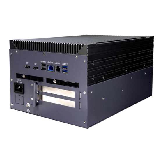
Page 9: Rear Panel I/O Placement
1.3 SCH34X2-A9 Rear Panel I/O Placement 1.4 SCH4X2-RA9 Front Panel I/O Placement www.perfectron.com... - Page 10 1.5 SCH4X2-RA9 Rear Panel I/O Placement 1.6 SCH4X2-A9 Mechanical Dimensions Single System : www.perfectron.com...
- Page 11 Dual System : 1.7 SCH3X2-RD7 Mechanical Dimensions Single System : www.perfectron.com...
- Page 12 Dual System : www.perfectron.com...
-
Page 13: Chapter 2 : Rear I/O Port
Chapter 2 : Rear I/O Port 2.1 LAN port LED Indications 2.5G LAN : 1G LAN : www.perfectron.com... -
Page 14: Chapter 3: System Setup
Put 2.5”SSD on the tray and make sure SSD is fixed and push the tray back. • Use Tri-angle security key to lock the tray door. 3.2 PCIe Card installation SCH4X2-A9/RA9 series supports two PCIe Gen3 x 8 slot : • Remove the back cover screws www.perfectron.com... - Page 15 • Remove the BKT-1 screw of the cover • Remove the BKT-2 screws of the cover www.perfectron.com...
- Page 16 • 2*PCIex8 Slot www.perfectron.com...
- Page 17 • Install PCIe Card • Lock BKT-2 screw www.perfectron.com...
- Page 18 • Lock BKT-1 screw • Lock back cover screws www.perfectron.com...
-
Page 19: Chapter 4: Ami Bios Utility
The Up and Down <Arrow> keys moves the cursor to select a setup Up/Down screen or sub-screen. The Plus and Minus <Arrow> keys changes the field value of a +− Plus/Minus particular setup setting. The <Tab> key selects the setup fields. www.perfectron.com... -
Page 20: Main Page
Display the installed CPU brand. Memory Information This displays the installed memory size, installed memory size of Slot 1 & Slot2, and the installed memory frequency. Serial ATA Port 4/5/6/7 Display the installed SATA device model/size of port 4/5/6/7. System Date www.perfectron.com... -
Page 21: Advance Page
0-23 mm: 0-59 ss: 0-59 4.4 Advance Page Onboard Device Onboard Device Configuration CPU Configuration CPU Configuration Parameters VMD setup menu VMD Configuration setting Trusted Computing Trusted Computing Settings NCT6126D Super IO Configuration System Super IO Chip Parameters. www.perfectron.com... -
Page 22: Onboard Device
Specify what state to go to when power is re-applied after a power failure (G3 state). S0 State / S5 State DVMT Pre-Allocated Select DVMT 5.0 Pre-Allocated (Fixed) Graphics Memory size used by the Internal Graphics Device. 32M/F7 / 36M / 40M / 44M / www.perfectron.com... -
Page 23: Cpu Configuration
Control Detection of the HD-Audio device. Disabled: HDA will be unconditionally disabled. Enabled: HDA will be unconditionally enabled. Disabled / Enabled Chassis Intrusion Configure Chassis Intrusion. Disabled / Enabled / Reset 4.4.2 CPU Configuration Displays CPU Signature Brand String Displays the CPU brand string www.perfectron.com... -
Page 24: Vmd Setup Menu
L3 Cache Size SMX/TXT SMX/TXT Supported or Not 4.4.3 VMD setup menu Enable VMD controller Enable/Disable to VMD controller. Disabled / Enabled www.perfectron.com... -
Page 25: Trusted Computing
Security Device. TCG EFI protocol and INT1A interface will not be available. Disabled / Enabled Pending operation Schedule an Operation for the ecurity Device. NOTE: Your Computer will reboot during restart in order to change State of Security Device. None / TPM Clear www.perfectron.com... -
Page 26: Nct6126D Super Io Configuration
4.4.5 NCT6126D Super IO Configuration Serial Port 1 Configuration Set Parameters of Serial Port 1 (COMA) Serial Port 2 Configuration Set Parameters of Serial Port 2 (COMB) www.perfectron.com... -
Page 27: Serial Port 1 Configuration
/ IO=228h, IRQ=3, 4, 5, 6, 7, 9, 10, 11, 12; Mode Configuration Configure serial port as RS232/RS422/RS485. 1T/1R RS422 / 3T/5R RS232 / 1T/1R RS485 TX ENABLE Low Active / 1T/1R RS422 with termination resistor / 1T/1R RS485 with termination resistor TX ENABLE Low Active / Disabled www.perfectron.com... -
Page 28: Serial Port 2 Configuration
/ IO=3E8h, IRQ=3, 4, 5, 6, 7, 9, 10, 11, 12; / IO=2E8h; IRQ=3, 4, 5, 6, 7, 9, 10, 11, 12; / IO=220h, IRQ=3, 4, 5, 6, 7, 9, 10, 11, 12; / IO=228h, IRQ=3, 4, 5, 6, 7, 9, 10, 11, 12; www.perfectron.com... -
Page 29: Hardware Monitor
Disabled / Enabled] System Fan Enable (Suppressed if Hardware Monitor Alert is Disabled) If Enabled, POST monitors system fan status. If this value is out of range, BIOS display warning message and turn on beep sound. Disabled / Enabled www.perfectron.com... -
Page 30: S5 Rtc Wake Settings
Wake up second(Show when Wake system from S5 set to Fixed Time) Select 0-59. For example enter 3 for 3am and 15 for 3pm. Wake system from S5 (when set to [Dynamic time]) Wake up minute increase Select 1-5. www.perfectron.com... -
Page 31: 10Network Stack Configuration
Enable/Disable Ipv4 PXE Boot Support. If disabled IPV4 PXE boot option will not be created. Disabled / Enabled Ipv6 PXE Support (Available when Network stack Enabled) Enable/Disable Ipv6 PXE Boot Support. If disabled IPV6 PXE boot option will not be created. Disabled / Enabled www.perfectron.com... -
Page 32: 11Nvme Configuration
4.4.11 NVMe Configuration (Device) Here shows the Device Name you installed. A sample screenshot shows below. www.perfectron.com... -
Page 33: Security Page
Press Enter when selected to go into the associated Sub-Menu. Secure Boot Set User Password. Press Enter when selected to go into the associated Sub-Menu. BIOS Update BIOS Update support Press Enter when selected to go into the associated Sub-Menu. www.perfectron.com... -
Page 34: Hdd Security Configuation
4.5.1 HDD Security configuation (Device) Read only www.perfectron.com... -
Page 35: Secure Boot
Restore Factory Keys Force System to User Mode. Install factory default Secure Boot key databases. Reset to Setup Mode Delete all Secure Boot key databases from NVRAM. Key Management Enables expert users to modify Secure Boot Policy variables without full authentication www.perfectron.com... -
Page 36: Key Management
Enroll Factory Defaults or load certificates from a file: 1.Public Key Certificate: a)EFI_SIGNATURE_LIST b)EFI_CERT_X509 (DER) c)EFI_CERT_RSA2048 (bin) d)EFI_CERT_SHAXXX 2.Authenticated UEFI Variable 3.EFI PE/COFF Image(SHA256) Key Source: Factory,External,Mixed Key Exchange Keys Enroll Factory Defaults or load certificates from a file: 1.Public Key Certificate: a)EFI_SIGNATURE_LIST www.perfectron.com... - Page 37 Enroll Factory Defaults or load certificates from a file: 1.Public Key Certificate: a)EFI_SIGNATURE_LIST b)EFI_CERT_X509 (DER) c)EFI_CERT_RSA2048 (bin) d)EFI_CERT_SHAXXX 2.Authenticated UEFI Variable 3.EFI PE/COFF Image(SHA256) Key Source: Factory,External,Mixed OsRecovery Signatures Enroll Factory Defaults or load certificates from a file: 1.Public Key Certificate: a)EFI_SIGNATURE_LIST b)EFI_CERT_X509 (DER) c)EFI_CERT_RSA2048 (bin) d)EFI_CERT_SHAXXX www.perfectron.com...
-
Page 38: Bios Update
Enroll Efi Image Allow the image to run in Secure Boot mode. Enroll SHA256 Hash certificate of a PE image into Authorized Signature Database (db) 4.5.4 BIOS Update Path for ROM Image Enter the path to the BIOS update option. www.perfectron.com... -
Page 39: Boot Page
Specifies the Boot Device Priority sequence from available Hard Disk Drives. (UEFI) USB KEY Drive BBS Priorities Specifies the Boot Device Priority sequence from available Hard Disk Drives. (UEFI) USB Hard Disk Drive BBS Priorities Specifies the Boot Device Priority sequence from available Hard Disk Drives. www.perfectron.com... -
Page 40: List Boot Device Type) Drive Bbs Priorities
4.6.1 (List Boot Device Type) Drive BBS Priorities Boot Option #1 Sets the system boot order. Boot Device Name #1 of this type / Disabled www.perfectron.com... -
Page 41: Save & Exit Page
4.7 Save & Exit Page Discard Changes and Exit Exit system setup without saving any changes. Save Changes and Reset Reset the system after saving the changes. Restore Defaults Restore/Load Default values for all the setup options. www.perfectron.com... -
Page 42: Event Logs
4.8 Event Logs Change Smbios Event Log Settings Press <Enter> to change the Smbios Event Log configuration. View Smbios Event Log Press <Enter> to change the Smbios Event Log records. www.perfectron.com... -
Page 43: Change Smbios Event Log Setting
Choose options for erasing Smbios Event Log. Erasing is done prior to any logging activation during reset. No / Yes, next reset / Yes, every reset Whea Log is Full Choose options for reactions to a full Smbios Event Log. Do Nothing / Erase Immediately www.perfectron.com... -
Page 44: Viewsmbios Event Log
4.8.2 ViewSmbios Event Log DATE / TIME / ERROR CODE / SEVERITY / COUNT Description: Log Area Reset and Count is applicable only for Multi- Events. By Events. MM/DD/YY HH:MM:SS Smbios 0x16 N/A N/A www.perfectron.com...
Need help?
Do you have a question about the SCH4X2-A9 and is the answer not in the manual?
Questions and answers