Table of Contents
Advertisement
Quick Links
Safe Operation Practices • Set-Up • Operation • Maintenance • Service • Troubleshooting • Warranty
'
operator
s manual
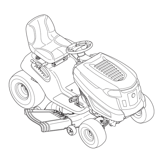
Auto Drive Lawn Tractor
WARNING
READ AND FOLLOW ALL SAFETY RULES AND INSTRUCTIONS IN THIS MANUAL
BEFORE ATTEMPTING TO OPERATE THIS MACHINE.
FAILURE TO COMPLY WITH THESE INSTRUCTIONS MAY RESULT IN PERSONAL INJURY.
LES DISTRIBUTIONS RVI LIMITÉE, 2955, JEAN-BAPTISTE DESCHAMPS, LACHINE, QUEBEC H8T 1C5
MTD LLC, P.O. BOX 361131 CLEVELAND, OHIO 44136-0019
Printed In USA
769-09691
1.30.14
Advertisement
Table of Contents

Related Manuals for Columbia 13AV90KS897


Summary of Contents for Columbia 13AV90KS897
- Page 1 Safe Operation Practices • Set-Up • Operation • Maintenance • Service • Troubleshooting • Warranty ’ operator s manual Auto Drive Lawn Tractor WARNING READ AND FOLLOW ALL SAFETY RULES AND INSTRUCTIONS IN THIS MANUAL BEFORE ATTEMPTING TO OPERATE THIS MACHINE. FAILURE TO COMPLY WITH THESE INSTRUCTIONS MAY RESULT IN PERSONAL INJURY.
-
Page 2: Table Of Contents
To The Owner Thank You Thank you for purchasing your new equipment. It was carefully The manufacturer reserves the right to change product engineered to provide excellent performance when properly specifications, designs and equipment without notice and operated and maintained. without incurring obligation. -
Page 3: Safe Operation Practices
Important Safe Operation Practices WARNING: This symbol points out important safety instructions which, if not followed, could endanger the personal safety and/or property of yourself and others. Read and follow all instructions in this manual before attempting to operate this machine. Failure to comply with these instructions may result in personal injury. - Page 4 Mow only in daylight or good artificial light. Never carry passengers. Mow up and down slopes, not across. Exercise extreme caution when changing direction on slopes. Disengage blade(s) before shifting into reverse. Back up slowly. Always look down and behind before and while Watch for holes, ruts, bumps, rocks, or other hidden backing to avoid a back-over accident.
- Page 5 Be alert and turn machine off if a child enters the When practical, remove gas-powered equipment area. from the truck or trailer and refuel it on the ground. If this is not possible, then refuel such equipment on Before and while backing, look behind and down for a trailer with a portable container, rather than from a small children.
-
Page 6: Spark Arrestor
Do not modify engine Mower blades are sharp. Wrap the blade or wear gloves, and use extra caution when servicing them. To avoid serious injury or death, do not modify engine in any Keep all nuts, bolts, and screws tight to be sure the way. - Page 7 Safety Symbols This page depicts and describes safety symbols that may appear on this product. Read, understand, and follow all instructions on the machine before attempting to assemble and operate. Symbol Description READ THE OPERATOR’S MANUAL(S) Read, understand, and follow all instructions in the manual(s) before attempting to assemble and operate DANGER—...
- Page 8 2 — i ection mportant peration racticeS...
-
Page 9: Assembly & Set-Up
Assembly & Set-Up Tractor Set-Up While holding the discharge chute with your left hand, remove the shipping brace with your right hand by NOTE: This Operators Manual covers a range of product grasping it between your thumb and index finger and specifications for various models. -
Page 10: Connecting The Battery Cables
Connecting the Battery Cables Checking Tire Pressure WARNING! CALIFORNIA PROPOSITION 65 WARNING! Do not overinflate tires. Check sidewall of tires for maximum psi. Equal tire pressure should Battery posts, terminals, and related accessories be maintained at all times. contain lead and lead compounds, chemicals known to the State of California to cause cancer and The tires on your tractor may be over inflated for shipping reproductive harm. - Page 11 Adjusting the Seat Lever Adjustment Seat To adjust the position of the seat, pull up and hold the seat adjustment lever. Slide the seat forward or rearward to the desired position; then release the adjustment lever. Make sure seat is locked into position before operating the tractor. See Figure 3-5.
-
Page 12: Controls & Features
Controls and Features Service Minder & Throttle/Choke Control Hour Meter Fuel Level Indicator (optional) Ignition Switch Module Electric PTO Knob (optional) Brake Pedal Drive Pedal Parking Brake/ Seat Adjustment Lever Cruise Control Lever Deck Lift Lever PTO (Blade Engage) Shift Lever Assembly Handle (optional) Storage Bin Figure 4-1... -
Page 13: Drive Pedal
Deck Lift Lever LCD Service Minder & Hour Meter When the ignition key is rotated out of the STOP position but not into the START position, the Found on your tractor’s right fender, the deck lift lever is used to LCD Service Minder and Hour change the height of the cutting deck. -
Page 14: Fuel Level Indicator
PTO/Blade Engage Handle Parking Brake/ Cruise Control Lever (If Equipped) Activating the PTO engages power to the cutting deck or other (separately available) attachments. Push forward on the PTO/Blade Engage handle to activate it. Pull the PTO/Blade Engage handle back to disengage the power to the cutting deck or other (separately available) attachments. -
Page 15: Operation
Operation Starting the Engine WARNING! Do not operate the tractor if the TO AVOID SERIOUS INJURY OR DEATH interlock system is malfunctioning. This system was designed for your safety and protection. • GO UP AND DOWN SLOPES, NOT ACROSS. • AVOID SUDDEN TURNS. NOTE: Refer to the Gasoline and Oil fill-up instructions in the •... -
Page 16: Driving The Tractor
Driving The Tractor Reverse Caution Mode WARNING! The REVERSE CAUTION MODE position of the key switch module Avoid sudden starts, excessive speed allows the tractor to be operated in reverse with the blades (PTO) and sudden stops. engaged. NOTE: Mowing in reverse is not recommended. Lightly press the brake pedal to release the parking brake. -
Page 17: Driving On Slopes
Driving On Slopes Setting The Cruise Control Refer to the SLOPE GAUGE on page 8 to help determine slopes WARNING! Never engage the cruise control lever where you may operate the tractor safely. while traveling in reverse. WARNING! Do not mow on inclines with a slope in excess of 15 degrees (a rise of approximately 2-1⁄2 feet every 10 feet). -
Page 18: Engaging The Pto
Engaging the PTO Engaging the PTO transfers power to the cutting deck or other (separately available) attachments. To engage the PTO: Move the Throttle/Choke control lever to the FAST (rabbit) position. Push the PTO/Blade Engage lever forward into the engaged (ON) position. -
Page 19: Maintenance & Adjustment
Maintenance & Adjustments Maintenance Schedule Before Every Every Every Every Prior Each use 10 Hours 25 Hours 50 Hours 100 Hours to Storing Clean Hood/Dash Louvers Check Engine Oil Level Check Air Filter for Dirty, Loose or Damaged Parts Clean and Re-oil Air Filter’s Foam Precleaner Replace Air Filter Element Change Engine Oil and Replace Oil Filter Clean Battery Terminals... -
Page 20: Cleaning The Tractor
Transmission Pop open the protective cap on the end of the oil drain valve to expose the drain port. See Fig 6-1. The transmission is sealed at the factory and is maintenance- free. The fluid level cannot be checked and the fluid cannot be changed. - Page 21 Lubrication Attach the hose coupler to the water port on your deck’s surface. See Fig. 6-2. WARNING! Before lubricating, repairing, or Turn the water on. inspecting, always disengage PTO, set parking brake, stop engine and remove key to prevent unintended starting. Front Wheels Each of the front wheel axles and rims is equipped with a grease fitting.
- Page 22 Adjustments Leveling the Deck (Side to Side) WARNING! If the cutting deck appears to be mowing unevenly, a side to side Shut the engine off, remove the adjustment can be performed. Adjust if necessary as follows: ignition key and engage the parking brake before making adjustments.
-
Page 23: Off-Season Storage
Adjusting the Seat Front tire toe-in can be measured as follows: Place the steering wheel in position for straight Refer to the Set-Up and Assembly section of this manual for seat ahead travel. adjustment instructions. In front of the axle, measure the distance WARNING! Before operating the tractor, make horizontally from the inside of the left rim to the... -
Page 24: Service
Service Cutting Deck Removal Place the PTO/Blade Engage lever/knob in the disengaged (OFF) position and engage the parking brake. Lower the deck by moving the deck lift lever into the bottom notch on the right fender. Locate the engine pulley (or electric PTO clutch if equipped) under the front of your tractor. -
Page 25: Changing The Deck Belt
Changing the Deck Belt For models with manual PTO, carefully remove the deck engage cable from the rear of the cutting deck by WARNING! removing the bow-tie cotter clip that secures it. Remove The V-belts found on your tractor are the spring from the deck idler bracket. -
Page 26: Cutting Blades
Cutting Blades To place the new belt, begin by routing the belt around the two outer spindle pulleys as shown in Fig. 7-7. WARNING! Shut the engine off and remove Then route the belt around the two deck idler pulleys as ignition key before removing the cutting blade(s) for shown in Fig. - Page 27 CAUTION: Start the tractor (as instructed in the Operation section of Use a torque wrench to tighten the this manual). blade spindle hex flange nut to between 70 ft-lbs and 90 ft-lbs. Set the tractor’s parking brake before removing the jumper cables, in reverse order of connection.
-
Page 28: Troubleshooting
Troubleshooting Problem Cause Remedy Engine fails to start 1. PTO/Blade Engage knob engaged. 1. Place knob in disengaged (OFF) position. 2. Parking brake not engaged. 2. Engage parking brake. 3. Spark plug wire(s) disconnected. 3. Connect wire(s) to spark plug(s). 4. -
Page 29: Attachments & Accessories
Attachments & Accessories The following attachments and accessories are compatible for your lawn tractor. See your authorized dealer or the retailer from which you purchased your tractor for information regarding price and availability. Caution: These lawn tractors are NOT designed for use with any type of ground-engaging attachments (e.g. tiller or moldboard plow). -
Page 30: Replacement Parts
Replacement Parts Component Part Number and Description 954-04060B Drive Belt 942-04308 2-in-1 Deck Blade 925-1707D Battery 918-04822A Deck Spindle 734-04155 Deck Wheel (Front) 734-0973 Deck Wheel (Rear) NOTE: Download a complete Parts Manual free of charge at www.mtdcanada.ca or phone (800) 668-1238 to purchase a Parts Manual. Be sure to have your model number and serial number ready. - Page 31 Component Part Number and Description 751-12182 Fuel Tank Cap 946-04364 Throttle/Choke Control Lever & Cable 925-1745A Ignition Key (Plastic) 631-04349 Discharge Chute Assembly NOTE: Download a complete Parts Manual free of charge at www.mtdcanada.ca or phone (800) 668-1238 to purchase a Parts Manual. Be sure to have your model number and serial number ready.
-
Page 32: Emission Control Warranty Statement
FEDERAL and/or CALIFORNIA EMISSION CONTROL WARRANTY STATEMENT YOUR WARRANTY RIGHTS AND OBLIGATIONS MTD Consumer Group Inc, the United States Environmental Protection Agency (EPA), and for those products certified for sale in the state of California, the California Air Resources Board (CARB) are pleased to explain the evaporative emission control system (ECS) warranty on your 2013-2014 small off-road equipment (outdoor equipment). - Page 33 Any replacement part may be used in the performance of any warranty maintenance or repairs and must be provided without charge to the owner. Such use will not reduce the warranty obligations of MTD Consumer Group Inc. Add-on or modified parts that are not exempted by the Air Resources Board may not be used. The use of any non-exempted add-on or modified parts by the ultimate purchaser will be grounds for disallowing a warranty claim.
-
Page 34: Three-Year Limited Warranty
For equipment purchased in Canada only. THREE YEAR LIMITED WARRANTY The limited warranty set forth below is given by MTD Products Limited with respect to new merchandise purchased and used in Canada and/or its territories and possessions (either entity respectively, “MTD”). MTD warrants this product (excluding its normal wear parts as described below) against defects in material and workmanship for a period of three (3) years commencing on the date of original purchase and will, at its option, repair or replace, free of charge, any part found to be defective in materials or workmanship. - Page 35 THREE YEARS- 120 Hrs. LIMITED WARRANTY For three (3) years-120 hrs. whichever come first, from the date of original purchase of COLUMBIA products, COLUMBIA will either repair or replace, at its option, free of charge, F.O.B. factory or authorized service firm, any part found to be defective in material and workmanship.
- Page 36 Notes...
Need help?
Do you have a question about the 13AV90KS897 and is the answer not in the manual?
Questions and answers