Table of Contents
Advertisement
Quick Links
Safe Operation Practices • Set-Up • Operation • Maintenance • Service • Troubleshooting • Warranty
'
operator
s manual
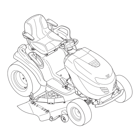
Model Series 94G - Hydrostatic Garden Tractor
WARNING
READ AND FOLLOW ALL SAFETY RULES AND INSTRUCTIONS IN THIS MANUAL
BEFORE ATTEMPTING TO OPERATE THIS MACHINE.
FAILURE TO COMPLY WITH THESE INSTRUCTIONS MAY RESULT IN PERSONAL INJURY.
LES DISTRIBUTIONS RVI LIMITÉE, 2955, JEAN-BAPTISTE DESCHAMPS, LACHINE, QUEBEC H8T 1C5
MTD LLC, P.O. BOX 361131 CLEVELAND, OHIO 44136-0019
Printed In USA
769-05886A
1.9.12
Advertisement
Table of Contents

Related Manuals for Columbia 94G Series


Summary of Contents for Columbia 94G Series
- Page 1 Safe Operation Practices • Set-Up • Operation • Maintenance • Service • Troubleshooting • Warranty ’ operator s manual Model Series 94G - Hydrostatic Garden Tractor WARNING READ AND FOLLOW ALL SAFETY RULES AND INSTRUCTIONS IN THIS MANUAL BEFORE ATTEMPTING TO OPERATE THIS MACHINE. FAILURE TO COMPLY WITH THESE INSTRUCTIONS MAY RESULT IN PERSONAL INJURY.
-
Page 2: Table Of Contents
To The Owner Thank You Thank you for purchasing your new equipment. It was carefully The manufacturer reserves the right to change product engineered to provide excellent performance when properly specifications, designs and equipment without notice and operated and maintained. without incurring obligation. -
Page 3: Safe Operation Practices
Important Safe Operation Practices WARNING: This symbol points out important safety instructions which, if not followed, could endanger the personal safety and/or property of yourself and others. Read and follow all instructions in this manual before attempting to operate this machine. Failure to comply with these instructions may result in personal injury. - Page 4 Mow only in daylight or good artificial light. Never carry passengers. Mow up and down slopes, not across. Exercise extreme caution when changing direction on slopes. Disengage blade(s) before shifting into reverse. Back up slowly. Always look down and behind before and while Watch for holes, ruts, bumps, rocks, or other hidden backing to avoid a back-over accident.
- Page 5 Be alert and turn machine off if a child enters the When practical, remove gas-powered equipment area. from the truck or trailer and refuel it on the ground. If this is not possible, then refuel such equipment on Before and while backing, look behind and down for a trailer with a portable container, rather than from a small children.
-
Page 6: Spark Arrestor
Do not modify engine Mower blades are sharp. Wrap the blade or wear gloves, and use extra caution when servicing them. To avoid serious injury or death, do not modify engine in any Keep all nuts, bolts, and screws tight to be sure the way. - Page 7 Safety Symbols This page depicts and describes safety symbols that may appear on this product. Read, understand, and follow all instructions on the machine before attempting to assemble and operate. Symbol Description READ THE OPERATOR’S MANUAL(S) Read, understand, and follow all instructions in the manual(s) before attempting to assemble and operate DANGER—...
- Page 8 2 — i ection mportant peration racticeS...
-
Page 9: Assembly & Set-Up
Assembly & Set-Up Contents of Crate • One Garden Tractor • One Oil Drain Tube • One Deck Wash Hose Coupler • One Garden Tractor Operator’s • One Engine Operator’s Manual • One Product Registration Card Manual Tractor Set-Up Shipping Brace Removal WARNING! Make sure the garden tractor’s engine Moving The Tractor Manually... - Page 10 Connecting the Battery Cables Checking Tire Pressure WARNING! Never exceed the maximum inflation CALIFORNIA PROPOSITION 65 WARNING! pressure shown on the sidewall of the tire. Do not Battery posts, terminals, and related accessories overinflate tires. Check sidewall of tires for maximum contain lead and lead compounds, chemicals known psi.
- Page 11 Position the deck roller brackets up or down through Gas and Oil the slots on the rear of the deck until desired The fuel tank is located under the hood. Remove the fuel cap by position is reached, then reattach with the clevis turning it counterclockwise.
-
Page 12: Controls & Features
Controls and Features Systems Indicator Monitor Fuel Tank Cap (optional) Electric PTO Button (optional) Throttle/Choke Control Ignition Switch Module Fuel Level Indicator Brake Pedal Drive Pedal Reverse Pedal Seat Adjustment Lever Parking Brake/ Cruise Control Lever Deck Lift Lever PTO (Blade Engage) Handle (optional) Storage Bin Figure 4-1... -
Page 13: Ignition Switch Module
Deck Lift Lever Systems Indicator Monitor/ Hour Meter LCD Found on your tractor’s right fender, the deck lift lever is used to change When the ignition key is rotated out of the height of the cutting deck. To the STOP position but not into the START HOURS 1/10 use, move the lever to the left, then position, the systems indicator monitor... -
Page 14: Fuel Level Indicator
Fuel Level Indicator Parking Brake/Cruise Control Lever The Fuel Level Indicator is located on the left side of the tractor’s dash and indicates the amount of fuel in the gas tank. Located in the center of the tractor’s dash panel below the steering wheel, the Parking Brake/Cruise Control lever is used to engage the parking brake and the cruise control. -
Page 15: Operation
Operation Starting the Engine WARNING! Do not operate the tractor if the TO AVOID SERIOUS INJURY OR DEATH interlock system is malfunctioning. This system was designed for your safety and protection. • GO UP AND DOWN SLOPES, NOT ACROSS. • AVOID SUDDEN TURNS. NOTE: Refer to the Set-Up and Assembly section of this manual •... -
Page 16: Driving The Tractor
Driving The Tractor Reverse Caution Mode WARNING! The REVERSE CAUTION MODE position of the key switch module Avoid sudden starts, excessive speed allows the tractor to be operated in reverse with the blades (PTO) and sudden stops. engaged. NOTE: Mowing in reverse is not recommended. Lightly press the brake pedal to release the parking brake. -
Page 17: Driving On Slopes
Driving On Slopes Cruise Control WARNING! Never engage the cruise control lever Refer to the SLOPE GAUGE on page 8 to help determine slopes while traveling in reverse. where you may operate the tractor safely. WARNING! Do not mow on inclines with a slope in excess of 15 degrees (a rise of approximately 2-1⁄2 To set the cruise control: feet every 10 feet). -
Page 18: Engaging The Pto
Engaging the PTO • For best results it is recommended that the first two laps be cut with the discharge thrown towards the center. After the Engaging the PTO transfers power to the cutting deck or other first two laps, reverse the direction to throw the discharge (separately available) attachments. -
Page 19: Maintenance & Adjustment
Maintenance & Adjustments Maintenance Schedule Before Every Every Every Every Prior Each use 10 Hours 25 Hours 50 Hours 100 Hours to Storing Clean Hood/Dash Louvers Check Engine Oil Level Check Air Filter for Dirty, Loose or Damaged Parts Clean and Re-oil Air Filter’s Foam Pre-Cleaner Replace Air Filter Element Change Engine Oil and Replace Oil Filter Clean Battery Terminals... -
Page 20: Cleaning The Tractor
Pop open the protective cap on the end of the oil drain Spark Plug valve to expose the drain port. See Fig 6-1. The spark plug should be cleaned and the gap reset once a season. Refer to the Engine Owner’s Manual for correct plug type and gap specifications. - Page 21 Attach the hose coupler to the water port on your deck’s Front Wheels surface. See Fig. 6-2. Each of the front wheel axles and rims is equipped with a grease fitting. See Fig. 6-3. Lubricate with a No. 2 multi-purpose grease applied with a grease gun after every 25 hours of tractor operation.
- Page 22 Adjustments Determine the approximate distance necessary for proper adjustment and proceed, if necessary. WARNING! Shut the engine off, remove the Locate the hex lock nut on the end of the deck hanger rod. ignition key and engage the parking brake before See Fig.
- Page 23 Leveling the Deck (Side to Side) Steering Adjustment If the cutting deck appears to be mowing unevenly, a side to side If the tractor turns tighter in one direction than the other, or if adjustment can be performed. Adjust if necessary as follows: the ball joints are being replaced due to damage or wear, the steering drag links may need to be adjusted.
- Page 24 Deck Rear Roller Adjustment The rear rollers on the mower deck are not designed to carry the weight of the deck. The rear rollers should be adjusted to approximately 1⁄4” to 1⁄2” above the ground when the deck is moved to the desired cutting height. Place the tractor on a smooth, flat surface, move the deck to the desired cutting height, and check the height of the rear rollers.
-
Page 25: Service
Service Cutting Deck Removal To remove the cutting deck, proceed as follows: Place the PTO/Blade Engage knob in the disengaged (OFF) Belt Guard position and engage the parking brake. Lower the deck by moving the deck lift lever into the bottom notch on the right fender. -
Page 26: Cutting Blades
Cutting Blades Remove the bowtie cotter pin connecting the deck sway rod to the tractor frame. See Fig. 7-4. WARNING! Shut the engine off and remove ignition key before removing the cutting blade(s) for sharpening or replacement. Protect your hands by using heavy gloves when grasping the blade WARNING! Periodically inspect the blade and/or... - Page 27 Jump Starting WARNING! Never jump start a damaged or frozen battery. Be certain the vehicles do not touch, and ignitions are off. Do not allow cable clamps to touch. Connect positive (+) cable to positive post (+) of your tractor’s discharged battery. Connect the other end of the cable to the (positive +) post of the jumper battery.
-
Page 28: Changing The Deck Belt
CAUTION: Always use a replacement fuse with the same amperage capacity as the blown fuse. Front Spindle Deck Idler Pulley Pulleys Changing the Deck Belt WARNING! Shut the engine off and remove ignition key before removing the cutting blade(s) for sharpening or replacement. -
Page 29: Troubleshooting
Troubleshooting Problem Cause Remedy Engine fails to start 1. PTO/Blade Engage knob engaged. 1. Place knob in disengaged (OFF) position. 2. Parking brake not engaged. 2. Engage parking brake. 3. Spark plug wire(s) disconnected. 3. Connect wire(s) to spark plug(s). 4. -
Page 30: Attachments & Accessories
Attachments & Accessories The following attachments and accessories are compatible for your garden tractor. See your dealer or the retailer from which you purchased your tractor for information regarding price and availability. Model Number Description OEM-190-032 Snow Thrower, 42” 19A40002100 Triple Bagger, 54”... -
Page 31: Replacement Parts
Replacement Parts Drive Belt (Mowing Deck) 54” Deck 954-04083 Deck Blade 2 in 1 942-0677B Deck Spindle 918-04608A Front Deck Wheel 734-04155 Battery 925-1707D Fuel Tank Cap 951-12182 Throttle/Choke Control Cable 746-04542 Ignition Key 925-1745A Discharge Chute Assembly 631-04092B... -
Page 32: Emission Control Warranty Statement
FEDERAL and/or CALIFORNIA EMISSION CONTROL WARRANTY STATEMENT YOUR WARRANTY RIGHTS AND OBLIGATIONS MTD Consumer Group Inc, the United States Environmental Protection Agency (EPA), and, for those products certified for sale in the state of California, the California Air Resources Board (CARB) are pleased to explain the emission (evaporative and/or exhaust) control system (ECS) warranty on your outdoor 2006 and later small off-road spark-ignited engine and equipment (outdoor equipment engine) In California, new outdoor equipment engines must be designed, built and equipped to meet the State’s stringent anti-smog standards (in other states, 1997 and later model year equipment must be designed, built, and equipped to meet the U.S. - Page 33 6. The outdoor equipment engine owner will not be charged for diagnostic labor that is directly associated with diagnosis of a defec- tive, emission-related warranted part, provided that such diagnostic work is performed at a warranty station. 7. MTD Consumer Group Inc is liable for damages to other engine or equipment components proximately caused by a failure under warranty of any warranted part.
-
Page 34: Three-Year Limited Warranty
For equipment purchased in Canada only. THREE YEAR LIMITED WARRANTY The limited warranty set forth below is given by MTD Products Limited with respect to new merchandise purchased and used in Canada and/or its territories and possessions (either entity respectively, “MTD”). MTD warrants this product (excluding its normal wear parts as described below) against defects in material and workmanship for a period of three (3) years commencing on the date of original purchase and will, at its option, repair or replace, free of charge, any part found to be defective in materials or workmanship. - Page 35 THREE YEARS- 120 Hrs. LIMITED WARRANTY For three (3) years-120 hrs. whichever come first, from the date of original purchase of COLUMBIA products, COLUMBIA will either repair or replace, at its option, free of charge, F.O.B. factory or authorized service firm, any part found to be defective in material and workmanship.
- Page 36 Notes...
Need help?
Do you have a question about the 94G Series and is the answer not in the manual?
Questions and answers