Table of Contents
Advertisement
Quick Links
Safety • Setup • Adjustments • Operation • Maintenance • Troubleshooting • Parts Lists • Warranty
OPERATOR'S MANUAL
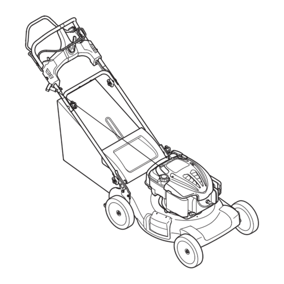
21" Self-Propelled Rotary Mower — Model Series J830
IMPORTANT:
READ SAFETY RULES AND INSTRUCTIONS
CAREFULLY BEFORE OPERATING EQUIPMENT.
LES DISTRIBUTIONS RVI LIMITÉE, 2955, JEAN-BAPTISTE DESCHAMPS, LACHINE, QUEBEC H8T 1C5
769-03848
PRINTED IN U.S.A.
02.08.08
Advertisement
Table of Contents

Subscribe to Our Youtube Channel
Related Manuals for Columbia 12AJ836L597


Summary of Contents for Columbia 12AJ836L597
- Page 1 Safety • Setup • Adjustments • Operation • Maintenance • Troubleshooting • Parts Lists • Warranty OPERATOR’S MANUAL 21” Self-Propelled Rotary Mower — Model Series J830 IMPORTANT: READ SAFETY RULES AND INSTRUCTIONS CAREFULLY BEFORE OPERATING EQUIPMENT. LES DISTRIBUTIONS RVI LIMITÉE, 2955, JEAN-BAPTISTE DESCHAMPS, LACHINE, QUEBEC H8T 1C5 769-03848 PRINTED IN U.S.A.
-
Page 2: Table Of Contents
This Operator’s Manual is an important part of your new equipment. It will help you assemble, prepare and maintain the unit for best performance. Please read and understand what it says. Table of Contents Slope Gauge............3 Adjustments ............. 11 Safe Operation Practices ........ -
Page 3: Slope Gauge
Use this page as a guide to determine slopes where you may not operate safely. Do not operate your lawn mower on such slopes. Slope Gauge WARNING Do not mow on inclines with a slope in excess of 15 degrees (a rise of approximately 2-1/2 feet every 10 feet). -
Page 4: Safe Operation Practices
WARNING: Engine Exhaust, some of its constituents, and certain vehicle components contain or emit chemicals known to the State of California to cause cancer and birth defects or other reproductive harm. DANGER: This machine was built to be operated according to the rules for safe operation in this manual. As with any type of power equipment, carelessness or error on the part of the operator can result in serious injury. - Page 5 3. Always be sure of your footing. A slip and fall can cause serious 13. To reduce fire hazard, keep mower free of grass, leaves, or personal injury. If you feel you are losing your balance, release other debris build-up. Clean up oil or fuel spillage and remove the blade control handle immediately, and the blade will stop any fuel soaked debris.
-
Page 6: Setup
NOTE: The units illustrated may vary slightly from your unit. 1. Remove loose parts and any packing material which may be between upper and lower handles. a. Pull up and back on the upper handle to raise the handle from position A into the operating position B. - Page 7 7. Attaching Grass Catcher to Mower a. Lift the rear discharge door. b. Place the grass catcher on the pivot rod. Let go of discharge door so that it rests on the grass catcher. See Figure 3-5. Setup & WARNING: Never operate mower unless the hooks on the grass Adjustment catcher are firmly seated on the pivot...
-
Page 8: Operation
Know Your Lawn Mower Drive Control Blade Control Operating Speed Control Your Lawn Electric Start Ignition Switch Mower Recoil Starter Cutting Height Adjustment Lever WARNING Mulch Plug Read, understand, and follow all instruc- tions and warnings on the machine and Figure 4-1 in this manual before operating. - Page 9 To Stop Engine 1. Release the blade control handle to stop the engine and blade. 2. Disconnect and ground the spark plug wire as instructed in the separate engine manual to prevent accidental starting while equipment is unattended. Operating WARNING: Wait for the blade to stop completely before doing any work Your Lawn on the mower or to remove the grass...
-
Page 10: Maintenance
Lubrication 1. Lubricate the pivot points on the blade control handle at least once a season with light oil. The blade control must operate freely in both directions. See Figure 5-1. 2. If your mower is equipped with ball bearing wheels, lubricate at least once a season with a light oil, all Maintaining other types require no lubrication. -
Page 11: Adjustments
Slot Maintaining Your Lawn Mower Figure 5-3 Figure 5-2 AdjustmentsVariable Speed Cable Periodic adjustment of the variable speed cable may be necessary due to normal wear on the drive system. Adjustment is needed if unit begins to run too slow or too WARNING fast. - Page 12 Blade Care Periodically inspect the blade adapter for cracks, especially if you strike a foreign object. Replace when necessary. Follow the steps below for blade service: 1. Disconnect spark plug boot from spark plug. Turn mower on its side making sure that the air filter and Maintaining Blade the carburetor are facing up.
- Page 13 Charging Battery 4. Carefully remove old battery and replace with new one. Connect the positive lead to the positive side of WARNING: The battery contains the battery pack, then connect the negative side. See corrosive fluid and toxic material; Figure 5-7. handle with care and keep away from children.
-
Page 14: Off-Season Storage
Replacing Fuse General Recommendations The electric starter circuit and battery are protected by a . Always observe safety rules when performing 40 ampere fuse. If the fuse burns out, the electric starter any maintenance. will not operate. If the unit fails to start with the electric 2. -
Page 15: Trouble Shooting
Problem Cause Remedy 1. Engage blade control handle. Engine fails to start 1. Blade control handle disengaged. 2. Connect wire to spark plug. 2. Spark plug wire disconnected. 3. Fill tank with clean, fresh gasoline. 3. Fuel tank empty or stale fuel. 4. -
Page 16: Illustrated Parts Lists
Model Series /Modèle de séries 830... - Page 17 PART N° DE N° DE RÉF PIÈCE DE SCRIP TION DE SCRIP TION 754-04176 V-Belt Courroie trapézoïdale 732-04338B Spring Le ver Levier de ressort 720-04096 Foam Grip Poignée de mousse Parts List 717-04540 Spur Gear 14T LH Engrenage 14 dents gauche 738-04278 Shoulder Screw 1/4-20 x .50 Vis à...
- Page 18 Model Series /Modèle de séries 830 Models with electric start Modèles avec démarreur électrique 4 22...
- Page 19 PART N° DE N° DE RÉF PIÈCE DE SCRIP TION DE SCRIP TION 746-04515 Drive Ca ble Câble de la commande 735-04059 Rub ber Grom met Grummet 687-02416 Drive Con trol Ass'y Commande d’embrayage de l’entraînement Parts List 732-04516 Shift Spring Ressort 747-04911A Blade Con trol Han dle...
-
Page 20: Warranty
TWO YEAR SUPREME WARRANTY: For two years from date of retail purchase within Canada, MTD PRODUCTS LIMITED will, at its option, repair or replace, for the original purchaser, free of charge, any part or parts found to be defective in material or workmanship. This warranty covers units which have been operated and maintained in accordance with the owner’s instructions furnished with the Warranty unit, and which have not been subject to misuse, abuse, commercial use, neglect, accident...
Need help?
Do you have a question about the 12AJ836L597 and is the answer not in the manual?
Questions and answers
What is the part number for the fuel cap replacement
The fuel cap replacement part number for Columbia 12AJ836L597 is BS-796577.
This answer is automatically generated