Table of Contents
Advertisement
Quick Links
Safety • Set-Up • Operation • Adjustments • Maintenance • Troubleshooting • Parts Lists • Warranty
OPERATOR'S MANUAL
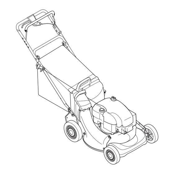
Model 978 shown.
21" Self-Propelled Rotary Mower — Model Series 900
IMPORTANT:
READ SAFETY RULES AND INSTRUCTIONS
CAREFULLY BEFORE OPERATING EQUIPMENT.
LES DISTRIBUTIONS RVI LIMITÉE, 2955, JEAN-BAPTISTE DESCHAMPS, LACHINE, QUEBEC H8T 1C5
769-04157D
PRINTED IN U.S.A.
1/21/11
Advertisement
Table of Contents

Related Manuals for Columbia 12A-999W897


Summary of Contents for Columbia 12A-999W897
- Page 1 Safety • Set-Up • Operation • Adjustments • Maintenance • Troubleshooting • Parts Lists • Warranty OPERATOR’S MANUAL Model 978 shown. 21” Self-Propelled Rotary Mower — Model Series 900 IMPORTANT: READ SAFETY RULES AND INSTRUCTIONS CAREFULLY BEFORE OPERATING EQUIPMENT. LES DISTRIBUTIONS RVI LIMITÉE, 2955, JEAN-BAPTISTE DESCHAMPS, LACHINE, QUEBEC H8T 1C5 769-04157D PRINTED IN U.S.A.
-
Page 2: Table Of Contents
This Operator’s Manual is an important part of your new equipment. It will help you assemble, prepare and maintain the unit for best performance. Please read and understand what it says. Table of Contents Slope Gauge............3 Operation............10 Safe Operation Practices ........4 Maintenance &... -
Page 3: Slope Gauge
Use this page as a guide to determine slopes where you may not operate safely. Do not operate your lawn mower on such slopes. Slope Gauge WARNING Do not mow on inclines with a slope in excess of 15 degrees (a rise of approximately 2-1/2 feet every 10 feet). -
Page 4: Safe Operation Practices
WARNING: Engine Exhaust, some of its constituents, and certain vehicle components contain or emit chemicals known to the State of California to cause cancer and birth defects or other reproductive harm. DANGER: This machine was built to be operated according to the rules for safe operation in this manual. As with any type of power equipment, carelessness or error on the part of the operator can result in serious injury. - Page 5 Children 22. Shut the engine off and wait until the blade comes to a complete stop before removing the grass catcher or ragic accidents can occur if the operator is not alert to unclogging the chute. The cutting blade continues to the presence of children.
- Page 6 9. Never over fill fuel tank. Fill tank to no more than ½ 8. Never attempt to make a wheel or cutting height inch below bottom of filler neck to provide for fuel adjustment while the engine is running. expansion. 9.
-
Page 7: Safety Symbols
This page depicts and describes safety symbols that may appear on this product. Read, understand, and follow all instructions on the machine before attempting to assemble and operate. Symbol Description READ THE OPERATOR’S MANUAL(S) Read, understand, and follow all instructions in the manual(s) before Safety attempting to assemble and operate Symbols... -
Page 8: Set-Up & Adjustments
NOTE: This owner’s manual covers various models of lawnmowers. The units illustrated may vary slightly from your unit. Follow only those instructions which pertain to your model lawnmower. 1. Remove loose parts and any packing material which may be between upper and lower handles. Pull up and back on the upper handle to raise the handle from position A. - Page 9 5. Bagging Grass Clippings. a. Remove wing nuts holding mulching plug (see Figure 4) or side discharge chute (see Figure 5) in place. Then remove baffle or discharge chute. b. Replace with bagging adapter (see Figure 6). Attach using wing nuts. Be sure that inner lip of Setup and attachment goes under the edge of the deck.
-
Page 10: Operating Your Lawn Mower
Know Your Lawn Mower Blade Control Drive Control Operating Shift Lever Your Lawn Mower Height Adjustment Lever Recoil Starter Grass Catcher Caster Locking Pin Side Deflector WARNING Read, understand, and follow all instruc- tions and warnings Mulch Plug on the machine and in this manual before * Casters are Axle Bolt and... - Page 11 4. To engage the drive, squeeze the drive control handle towards the upper handle. Release the drive control to slow down when negotiating an obstacle, making a turn, or stopping. 5. The six speed shift lever is located on the drive clutch control housing on the upper handle.
- Page 12 NOTE: This spark ignition system meets all require- ments of the Canadian Interference-Causing Equipment Regulations. 5. Clean the engine regularly with a cloth or brush. Keep the cooling system (blower housing area) clean to permit proper air circulation which is essential to engine performance and life.
- Page 13 Blade Care Periodically inspect the blade adapter for cracks, especially if you strike a foreign object. Replace when necessary. Follow the steps below for blade service: 1. Remove the bolt and the blade bell support which hold the blade and the blade adapter to the engine Maintenance crankshaft.
- Page 14 10. Using a pair of pliers, pull back and rotate belt keeper bracket from the slot on idler pulley. 11. Slide the belt out from between the belt keeper bracket and the idler pulley. See Figure 16. 12. Squeeze the belt together and push belt forward. Press the control arm inward towards the deck and Maintenance remove the six speed cable from the slot.
- Page 15 24. Pivot the baffle back to its original position and secure Off-Season Storage with three hex screws earlier removed. You will need a The following steps should be taken to prepare your 3/8” socket for these screws. lawn mower for storage. 25.
-
Page 16: Trouble Shooting
Problem Cause Remedy 1. Engage blade control handle. Engine fails to start 1. Blade control handle disengaged. 2. Spark plug wire disconnected. 2. Connect wire to spark plug. 3. Fuel tank empty or stale fuel. 3. Fill tank with clean, fresh gasoline. 4. -
Page 17: Parts List
Component Part Number and Description 734-2044B Wheel (Rear) 734-2004A Wheel (Front, models w/o front wheel casters) 734-1857 Wheel (Front, models w/ front wheel casters) Parts List 731-1832 Side Discharge Chute 664-0076A Grass Bag For parts and/or accessories refer to 942-0741A Mulching Blade customer support on page 2. -
Page 18: Replacement Parts
For equipment purchased in Canada only. THREE YEAR LIMITED WARRANTY The limited warranty set forth below is given by MTD Products Limited with respect to new merchandise purchased and used in Canada and/or its territories and possessions (either entity respectively, “MTD”). MTD warrants this product (excluding its normal wear parts as described below) against defects in material and workmanship for a period of three (3) years commencing on the date of original purchase and will, at its option, repair or replace, free of charge, any part found to be defective in materials or workman- ship. -
Page 19: Warranty
THREE YEARS- 120 Hrs. LIMITED WARRANTY For three (3) years-120 hrs. whichever come first, from the date of original purchase of COLUMBIA products, COLUMBIA will either repair or replace, at its option, free of charge, F.O.B. factory or authorized service firm, any part found to be defective in material and workmanship. - Page 20 NOTES...
Need help?
Do you have a question about the 12A-999W897 and is the answer not in the manual?
Questions and answers