Table of Contents
Advertisement
Quick Links
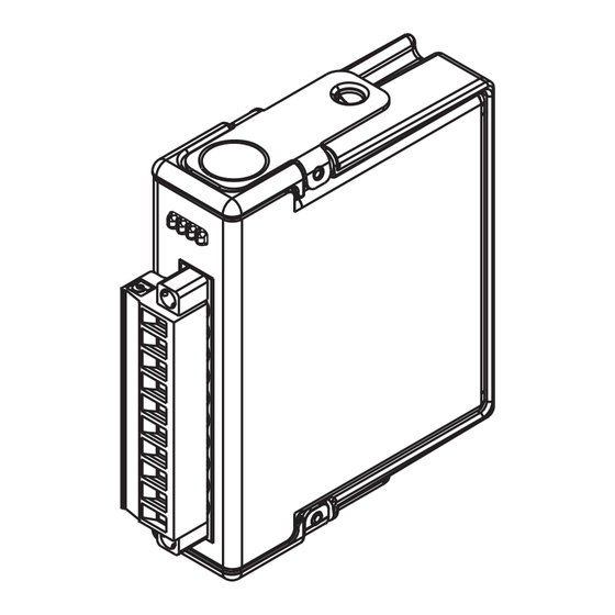
NI NI 9502
C Series Brushless Servo Drive Motor Module
A l l t r a d e m a r k s , b r a n d n a m e s , a n d b r a n d s a p p e a r i n g h e r e i n a r e t h e p r o p e r t y o f t h e i r r e s p e c t i v e o w n e r s .
• C r i t i c a l a n d e x p e d i t e d s e r v i c e s
• I n s t o c k / R e a d y - t o - s h i p
Artisan Scientific Corporation dba Artisan Technology Group is not an affiliate, representative, or authorized distributor for any manufacturer listed herein.
In Stock
Used and in Excellent Condition
Open Web Page
https://www.artisantg.com/44006-1
• We b u y y o u r e x c e s s , u n d e r u t i l i z e d , a n d i d l e e q u i p me n t
• F u l l - s e r v i c e , i n d e p e n d e n t r e p a i r c e n t e r
Advertisement
Table of Contents

Related Manuals for National Instruments 9502


Summary of Contents for National Instruments 9502
- Page 1 NI NI 9502 C Series Brushless Servo Drive Motor Module In Stock Used and in Excellent Condition Open Web Page https://www.artisantg.com/44006-1 A l l t r a d e m a r k s , b r a n d n a m e s , a n d b r a n d s a p p e a r i n g h e r e i n a r e t h e p r o p e r t y o f t h e i r r e s p e c t i v e o w n e r s .
- Page 2 OPERATING INSTRUCTIONS AND SPECIFICATIONS NI 9502 Brushless Servo Motor Drive Français Deutsch ni.com/manuals...
-
Page 3: Related Information
This document describes how to use the National Instruments 9502 module and includes specifications and pin assignments for the NI 9502. The safety guidelines and specifications in this Note document are specific to the NI 9502. The other components in the system may not meet the same safety ratings and specifications. -
Page 4: Safety Guidelines For Hazardous Locations
Safety Guidelines for Hazardous Locations The NI 9502 is suitable for use in Class I, Division 2, Groups A, B, C, D, T4 hazardous locations; Class I, Zone 2, AEx nA IIC T4 and Ex nA IIC T4 hazardous locations; and nonhazardous locations only. - Page 5 II 3G and is suitable for use in Zone 2 hazardous locations, in ambient temperatures of -40 °C Ta 70 °C. If you are using the NI 9502 in Gas Group IIC hazardous locations, you must use the device in an NI chassis that has been evaluated as Ex nC IIC T4, Ex IIC T4, Ex nA IIC T4, or Ex nL IIC T4 equipment.
-
Page 6: Electromagnetic Compatibility Guidelines
To minimize NI 9502 Operating Instructions and Specifications | © National Instruments | 5... - Page 7 To ensure compliance with the applicable Caution regulatory requirements, product installation requires special considerations and user-installed, add-on devices. Refer to the Connecting the NI 9502 Cable Requirements for EMC Compliance sections for details. 6 | ni.com | NI 9502 Operating Instructions and Specifications...
-
Page 8: Special Guidelines For Marine Applications
In addition, take precautions when designing, selecting, and installing measurement probes and cables to ensure that the desired EMC performance is attained. NI 9502 Operating Instructions and Specifications | © National Instruments | 7... - Page 9 The NI 9502 returns the motor current to the LabVIEW FPGA module for use in a current loop or for monitoring. NI 9502 status information such as drive status and drive faults are also returned to the LabVIEW FPGA module. Refer to the NI 9502 topic in the LabVIEW Help, available by selecting Help»LabVIEW Help, for...
- Page 10 Command* Velocity Current Velocity Loop Loop Command Velocity Feedback Bridge 3-Phase Velocity Motor Controller Bridge Generator Estimator Motor Current Current Sense Hall Sensor Inputs * Proportional to Torque NI 9502 Operating Instructions and Specifications | © National Instruments | 9...
- Page 11 Figure 2 shows the NI 9502 working with the LabVIEW FPGA module in FOC commutation mode. Figure 2. NI 9502 FOC Commutation Mode Block Diagram LabVIEW FPGA Module NI 9502 Position Setpoint Fault Fault Detection Monitor Velocity Current Command Command*...
- Page 12 Do not turn on or plug in the motor DC power Caution supply until the screw-terminal connector is fully inserted and the two connector flange screws are tightened. NI 9502 Operating Instructions and Specifications | © National Instruments | 11...
- Page 13 Figure 3. NI 9502 Connections Phase U Phase V Phase W Reserved Hall 1 Hall 2 Hall 3 Vsup (Chassis Ground) 12 | ni.com | NI 9502 Operating Instructions and Specifications...
- Page 14 Refer to Figure 4 for an illustration of using ferrules. Figure 4. 10-Terminal Detachable Screw-Terminal Connector with Ferrule Ferrule NI 9502 Operating Instructions and Specifications | © National Instruments | 13...
- Page 15 For proper phase switching to occur, the Hall sensors from the motor must be connected to the correct Hall inputs on the NI 9502 module. The Hall sensor phase sequence is motor-dependent, so selecting the correct inputs may require manually testing the motor wiring.
-
Page 16: Led Indicators
Help, available by selecting Help»LabVIEW Help, for information about determining the proper Hall input connections to the NI 9502 module when using the NI 9502 module in trapezoidal commutation mode. The LabVIEW SoftMotion Module provides an Note example that allows you to automatically determine the phasing for FOC commutation mode. - Page 17 You can define the User LED (yellow) to meet the needs of your application. Use the User LED I/O node to turn this LED on and off. Refer to the NI 9502 topic in the LabVIEW Help, available by selecting Help»LabVIEW Help, for information about the NI 9502 User LED I/O node.
- Page 18 • Module current sampling fault. Refer to the NI 9502 Module Faults topic in the LabVIEW Help, available by selecting Help»LabVIEW Help, for more information about this fault NI 9502 Operating Instructions and Specifications | © National Instruments | 17...
-
Page 19: Sleep Mode
Hot-Swap Behavior The NI 9502 is always disabled when it is first inserted in the chassis, regardless of whether Vsup is present or not. You can enable the drive using the Enable Drive method in software. Refer to the NI 9502 topic in the LabVIEW Help, available by selecting Help»LabVIEW Help, for more information about enabling the... - Page 20 Select and install cables for the NI 9502 in accordance with the following requirements: • Use only shielded cables to connect the NI 9502 to a motor and a power supply. • Terminate the motor and power supply cable shields to the COM terminal of the NI 9502.
- Page 21 (marked as Ferrite 2 in Figure ) and the motor cable (marked as Ferrite 3 in Figure ) as close to the NI 9502 as practical. If a single, shielded cable is used, install only one ferrite bead (marked as Ferrite 2 in Figure ) as shown.
- Page 22 Phase U Motor Phase V Phase W Hall 1 Hall 2 Hall 3 Motor DC Power Vsup Supply Ferrites. Refer to Tables 1 and 2 for sizing information. NI 9502 Operating Instructions and Specifications | © National Instruments | 21...
- Page 23 Motor Phase V Phase W Hall 1 Hall 2 Ferrite 3 Hall 3 Motor DC Power Vsup Supply Ferrite 2 Ferrites. Refer to Tables 1 and 2 for sizing information. 22 | ni.com | NI 9502 Operating Instructions and Specifications...
-
Page 24: Specifications
Maximum peak time....1 second Minimum dwell time between peaks ......15 seconds Peak output power...... 0.2 kW Continuous output power ... 0.1 kW Commutation......Field Oriented Control or Trapezoidal NI 9502 Operating Instructions and Specifications | © National Instruments | 23... - Page 25 Hall inputs Digital logic levels Voltage ......... -0.25 to 5.25 V High, VIH ......2.4 V min Low, VIL......0.8 V max Specifications based on the installed examples. 24 | ni.com | NI 9502 Operating Instructions and Specifications...
-
Page 26: Drive Protection
Active mode ....... 700 mW max Sleep mode ......... 2.5 mW max Thermal dissipation (at 70 °C) Active mode ....... 1.5 W max Sleep mode ......... 2.5 mW max NI 9502 Operating Instructions and Specifications | © National Instruments | 25... -
Page 27: Physical Characteristics
Torque for screw terminals..0.5 to 0.6 N · m (4.4 to 5.3 lb · in.) Wires per screw terminal.... One wire per screw terminal, two when using 2-wire ferrule Ferrules........0.25 mm to 2.5 mm 26 | ni.com | NI 9502 Operating Instructions and Specifications... -
Page 28: Safety Voltages
MAINS voltage. MAINS is a hazardous live electrical supply system that powers equipment. This category is for NI 9502 Operating Instructions and Specifications | © National Instruments | 27... -
Page 29: Hazardous Locations
Such voltage measurements include signal levels, special equipment, limited-energy parts of equipment, circuits powered by regulated low-voltage sources, and electronics. Do not connect the NI 9502 to signals or use for Caution measurements within Measurement Categories II, III, or IV. -
Page 30: Power Supply Requirements
UL 60079-0; Ed 5, UL 60079-15; Ed 3 • CSA 60079-0:2011, CSA 60079-15:2012 For UL and other safety certifications, refer to the Note product label or the Online Product Certification section. NI 9502 Operating Instructions and Specifications | © National Instruments | 29... -
Page 31: Electromagnetic Compatibility
ICES-001: Class A emissions For the standards applied to assess the EMC of this Note product, refer to the Online Product Certification section. For EMC compliance, operate this device with Note shielded cabling. 30 | ni.com | NI 9502 Operating Instructions and Specifications... -
Page 32: Online Product Certification
To obtain product certifications and the DoC for this product, visit ni.com/ , search by module number or product line, and certification click the appropriate link in the Certification column. NI 9502 Operating Instructions and Specifications | © National Instruments | 31... -
Page 33: Shock And Vibration
Operating temperature (IEC 60068-2-1, IEC 60068-2-2) ..-40 to 70 °C Storage temperature (IEC 60068-2-1, IEC 60068-2-2) ..-40 to 85 °C Ingress protection......IP 40 32 | ni.com | NI 9502 Operating Instructions and Specifications... -
Page 34: Environmental Management
Our Environmental Impact web page at ni.com/environment This page contains the environmental regulations and directives with which NI complies, as well as other environmental information not included in this document. NI 9502 Operating Instructions and Specifications | © National Instruments | 33... - Page 35 National Instruments WEEE initiatives, and compliance with WEEE Directive 2002/96/EC on Waste and Electronic Equipment, visit ni.com/environment/ weee National Instruments (RoHS) National Instruments RoHS (For information ni.com/environment/rohs_china about China RoHS compliance, go to ni.com/ environment/rohs_china 34 | ni.com | NI 9502 Operating Instructions and Specifications...
-
Page 36: Worldwide Support And Services
Worldwide Support and Services The National Instruments website is your complete resource for technical support. At you have access to ni.com/support everything from troubleshooting and application development self-help resources to email and phone assistance from NI Application Engineers. A Declaration of Conformity (DoC) is our claim of compliance with the Council of the European Communities using the manufacturer’s declaration of conformity. - Page 37 For patents covering National Instruments products/technology, refer to the appropriate location: Help»Patents in your software, the patents.txt file on your media, or the National Instruments Patent Notice at ni.com/patents . You can find information about end-user license agreements (EULAs) and third-party legal notices in the readme file for your NI product.
Need help?
Do you have a question about the 9502 and is the answer not in the manual?
Questions and answers