Table of Contents
Advertisement
Quick Links
Advertisement
Table of Contents

Related Manuals for National Instruments NI 9505E


Summary of Contents for National Instruments NI 9505E
- Page 1 sbRIO-9505...
- Page 2 OPERATING INSTRUCTIONS AND SPECIFICATIONS NI 9505E DC Brushed Servo Drive...
- Page 3 This document describes how to use the National Instruments 9505E module and includes dimensions, pin assignments, and specifications for the NI 9505E DC brushed servo drive. Visit and enter ni.com/info rdsoftwareversion to determine which software you need for the modules you are using.
- Page 4 NI 9505E Dimensions The following figure shows the dimensions of the NI 9505E. 73.4 (2.89) 0.0 (0.00) Figure 1. NI 9505E Dimensions in Millimeters (Inches) © National Instruments Corp. NI 9505E Operating Instructions and Specifications...
- Page 5 Module Specific\NI 9505 implementing each of these loops. The NI 9505E returns the motor or actuator current data to the LabVIEW FPGA Module for use in a current loop or for monitoring. The NI 9505E also returns status information such as...
- Page 6 The LabVIEW FPGA Module generates a PWM signal and sends the signal to the NI 9505E. The PWM signal is proportional to the desired current or torque you want to provide to the motor or actuator.
- Page 7 H-Bridge Servo Loop Loop Loop Controller Motor Position Velocity Current Feedback Feedback Feedback Velocity Estimator Current Sense Encoder Feedback Position Encoder Decoder Feedback * Proportional to Torque Figure 2. NI 9505E Block Diagram ni.com NI 9505E Operating Instructions and Specifications...
- Page 8 LabVIEW FPGA Module Acceleration Velocity Position Error Current Command Position (Proportional to Torque) Setpoint Position Feedback Encoder Feedback Position Decoder Figure 3. LabVIEW FPGA Module NI 9505E PID Loop © National Instruments Corp. NI 9505E Operating Instructions and Specifications...
- Page 9 (from NI 9505E) Figure 4. LabVIEW FPGA Module NI 9505E Current Loop Hot-Swap Behavior The NI 9505E is always disabled when it is inserted in the chassis, is present or not. You can enable the regardless of whether V drive using the Enable Drive method in software. Refer to the NI 9505 Reference Help book in the LabVIEW Help, available by selecting Help»Search the LabVIEW Help, for more...
-
Page 10: Led Indicators
3 Disable (yellow) (Motor Power) (green) 4 Fault (red) Power The Power LED (green) illuminates when the NI 9505E is properly inserted into a powered chassis. Note The Power LED does not illuminate when the chassis is in sleep mode. - Page 11 The Fault LED (red) illuminates when a fault occurs. A fault disables the drive. Causes for fault are the following: greater than 40 V will result in damage to Caution the NI 9505E. • Overvoltage • Undervoltage ni.com NI 9505E Operating Instructions and Specifications...
-
Page 12: Sleep Mode
Typically, when a system is in sleep mode, you cannot communicate with the modules. In sleep mode, the system consumes minimal power and may dissipate less heat than it does © National Instruments Corp. NI 9505E Operating Instructions and Specifications... - Page 13 Wiring the NI 9505E The NI 9505E has a 9-pin female DSUB connector that provides connections for the encoder inputs, a +5 V connection for encoder power, a connection for an emergency stop input, and a connection to COM.
- Page 14 Table 1. NI 9505E DSUB Pin Assignments Connector Signal Encoder Phase A+ Encoder Phase B+ Encoder Index+ (Phase Z+) Emergency Stop (E-Stop) +5 V (output) Encoder Phase A– Encoder Phase B– Encoder Index– (Phase Z–) Common (COM) Table 2. NI 9505E Screw-Terminal Terminal Assignments...
- Page 15 Figure 5 shows a typical NI 9505E connection example, including encoder and E-Stop inputs. Shield Phase A± Encoder Phase B± Feedback Index± +5 V +24 V E-Stop Shield Motor M– Shield Motor DC Power Supply NI 9505E Figure 5. NI 9505E Connections ni.com...
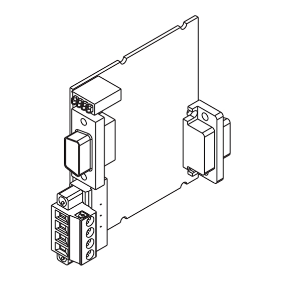
- Page 16 National Instruments sales representative. Refer to the section for more information. Refer to Figure 6 for Specifications an illustration. Figure 6. NI 9505E Module with Optional Screw-Terminal Accessory © National Instruments Corp. NI 9505E Operating Instructions and Specifications...
- Page 17 Reverse—Counterclockwise (CCW) facing motor shaft Figure 7 shows clockwise and counterclockwise motor rotation. Figure 7. Clockwise and Counterclockwise Motor Rotation If the motor does not turn in the desired direction, reverse the MOTOR+ and MOTOR– signals. ni.com NI 9505E Operating Instructions and Specifications...
-
Page 18: Encoder Signals
Encoder Signals The encoder signals consist of a Phase A, Phase B, and Index (Phase Z) input. The NI 9505E supports differential and single-ended inputs for Phase A, Phase B, and Index (Phase Z) signals. Figures 8 and 9 show simplified schematic diagrams of the encoder input circuit connected to differential and single-ended inputs. - Page 19 If the encoder cable length is greater than 3.05 m (10 ft), use encoders with differential line driver outputs for your applications. Power for a +5 V encoder—generated by a power supply on the NI 9505E—is available on pin 5 of the DSUB connector. Encoder NI 9505E...
- Page 20 Refer to Figure 7 for a depiction of clockwise and counterclockwise rotation. If encoder counting does not behave as expected, change the encoder polarity in the FPGA or swap the Phase A and Phase B connections. © National Instruments Corp. NI 9505E Operating Instructions and Specifications...
-
Page 21: Emergency Stop Signal
When connecting the encoder wiring to the NI 9505E, use shielded wire of at least 24 AWG. You must use cables with twisted pairs and an overall shield for improved noise immunity. Refer to Figure 5 for a connection example. - Page 22 • Tie the V cable shield to chassis ground at the module side only. • Tie the motor cable shield to chassis ground at the motor side only. © National Instruments Corp. NI 9505E Operating Instructions and Specifications...
- Page 23 Using the NI 9505E with Other C Series Modules Due to additional ambient heating of the NI 9505E when supplying more than 1 A to the load, the room temperature (25 ºC, ± 5 ºC) specifications of adjacent modules are not valid. The full operating temperature (–40 ºC to 85 ºC) specifications for these modules are...
-
Page 24: Specifications
........12 A < 2 s max For more information about maximum continuous current at temperatures less than 85 ºC, visit and enter ni.com/info rdmot2 Allow at least 3.4 s between peak current intervals. © National Instruments Corp. NI 9505E Operating Instructions and Specifications... - Page 25 ADC resolution ......12 bits Current range......±12.7 A Maximum update rate....20 µs Minimum inductance ......500 µH MTBF ..........821,178 hours at 25 ºC; Bellcore Issue 2, Method 1, Case 3, Limited Part Stress Method ni.com NI 9505E Operating Instructions and Specifications...
- Page 26 Temperature fault trip point ....115 ºC (module temperature) Encoder Input Characteristics Number of inputs ......3 Input type .......... Differential or single-ended Voltage range ........0 to 5.5 VDC © National Instruments Corp. NI 9505E Operating Instructions and Specifications...
- Page 27 Input voltage range ......0 to 30 V Input ON voltage ......3.5 to 30 V Input OFF voltage ...... 0 to 2 V Turn-on current ......... 500 µA, typical 1 mA, maximum ni.com NI 9505E Operating Instructions and Specifications...
-
Page 28: Power Requirements
Note For two-dimensional drawings and three-dimensional models of the C Series module and connectors, visit and search by module number. ni.com/dimensions © National Instruments Corp. NI 9505E Operating Instructions and Specifications... - Page 29 (0.28 in.) of insulation stripped from the end Torque for screw-terminals..0.5 to 0.6 N · m (4.4 to 5.3 lb · in.) Ferrules........0.25 mm to 1.5 mm Weight ........40 g (1.4 oz) ni.com NI 9505E Operating Instructions and Specifications...
- Page 30 This category is for measurements of voltages from specially protected secondary circuits. Such voltage measurements include signal levels, special equipment, limited-energy parts of equipment, circuits powered by regulated low-voltage sources, and electronics. © National Instruments Corp. NI 9505E Operating Instructions and Specifications...
-
Page 31: Safety Standards
Caution Do not connect the NI 9505E to signals or use for measurements within Measurement Categories II, III, or IV. Safety Standards This product meets the requirements of the following standards of safety for electrical equipment for measurement, control, and laboratory use when installed in a suitable enclosure: •... -
Page 32: Environmental Management
Maximum altitude......2,000 m Pollution Degree ....... 2 Environmental Management National Instruments is committed to designing and manufacturing products in an environmentally responsible manner. NI recognizes that eliminating certain hazardous substances from our products is beneficial to the environment and to NI customers. - Page 33 WEEE recycling center. For more information about WEEE recycling centers and National Instruments WEEE initiatives, visit ni.com/ environment/weee National Instruments (RoHS) National Instruments RoHS (For information ni.com/environment/rohs_china about China RoHS compliance, go to ni.com/ environment/rohs_china ni.com NI 9505E Operating Instructions and Specifications...
-
Page 34: Where To Go For Support
Where to Go for Support The National Instruments Web site is your complete resource for technical support. At you have access to ni.com/support everything from troubleshooting and application development self-help resources to email and phone assistance from NI Application Engineers. - Page 35 For patents covering National Instruments products/technology, refer to the appropriate location: Help»Patents in your software, the patents.txt file on your media, or the National Instruments Patent Notice at ni.com/patents .
Need help?
Do you have a question about the NI 9505E and is the answer not in the manual?
Questions and answers