
Related Manuals for National Instruments NI 9505


Summary of Contents for National Instruments NI 9505
- Page 1 OPERATING INSTRUCTIONS AND SPECIFICATIONS NI 9505 DC Brushed Servo Drive Français Deutsch ni.com/manuals...
-
Page 2: Related Information
This product may cause radio interference in Caution a domestic environment, in which case supplementary mitigation measures may be required. Related Information 2 | ni.com | NI 9505 Operating Instructions and Specifications... -
Page 3: Safety Guidelines For Hazardous Locations
Safety Guidelines for Hazardous Locations The NI 9505 is suitable for use in Class I, Division 2, Groups A, B, C, D, T4 hazardous locations; Class I, Zone 2, AEx nA IIC T4 and Ex nA IIC T4 hazardous locations; and nonhazardous locations only. - Page 4 II 3G and is suitable for use in Zone 2 hazardous locations, in ambient temperatures of -40 °C Ta 70 °C. If you are using the NI 9505 in Gas Group IIC hazardous locations, you must use the device in an NI chassis that has been evaluated as Ex nC IIC T4, Ex IIC T4, Ex nA IIC T4, or Ex nL IIC T4 equipment.
-
Page 5: Electromagnetic Compatibility Guidelines
To minimize NI 9505 Operating Instructions and Specifications | © National Instruments | 5... - Page 6 The inputs/outputs of this product can be Caution damaged if subjected to Electrostatic Discharge (ESD). To prevent damage, industry-standard ESD prevention measures must be employed during installation, maintenance, and operation. 6 | ni.com | NI 9505 Operating Instructions and Specifications...
- Page 7 LabVIEW FPGA Module in a typical motion control application. Figures 2 and 3 show more detailed versions of the position, velocity, and current loops implemented in the NI 9505 Operating Instructions and Specifications | © National Instruments | 7...
- Page 8 The LabVIEW FPGA Module generates a PWM signal and sends the signal to the NI 9505. The PWM signal is proportional to the desired current or torque you want to provide to the motor or actuator.
- Page 9 Refer to Figure 1 for a typical NI 9505 connection example, including encoder and E-Stop inputs. For more advanced motion control applications, SoftMotion provides functions for trajectory generation, spline interpolation, position and velocity PID control, and encoder implementation using both the LabVIEW Real-Time Module and the LabVIEW FPGA Module.
- Page 10 Current Position Bridge H-Bridge Servo Loop Loop Loop Controller Motor Position Velocity Current Feedback Feedback Feedback Velocity Estimator Current Sense Encoder Feedback Position Encoder Decoder Feedback * Proportional to Torque 10 | ni.com | NI 9505 Operating Instructions and Specifications...
- Page 11 Figure 2. LabVIEW FPGA Module NI 9505 PID Loop LabVIEW FPGA Module Acceleration Velocity Position Error Current Command Position (Proportional to Torque) Setpoint Position Feedback Encoder Feedback Position Decoder NI 9505 Operating Instructions and Specifications | © National Instruments | 11...
- Page 12 (from NI 9505) Hot-Swap Behavior The NI 9505 is always disabled when it is inserted in the chassis, regardless of whether VSUP is present or not. You can enable the drive using the Enable Drive method in software. Refer to the NI 9505 Reference Help book in the LabVIEW Help, available by selecting Help»Search the LabVIEW Help, for more...
-
Page 13: Led Indicators
The Power LED does not illuminate when the Note chassis is in sleep mode. VSUP The VSUP LED (green) illuminates when the motor DC power supply is properly connected and powering the drive. NI 9505 Operating Instructions and Specifications | © National Instruments | 13... - Page 14 The drive is disabled by default at power-on. You can enable the drive using the Enable Drive method in software. Refer to the NI 9505 Reference Help book in the LabVIEW Help, available by selecting Help»Search the LabVIEW Help, for more information about this method.
-
Page 15: Sleep Mode
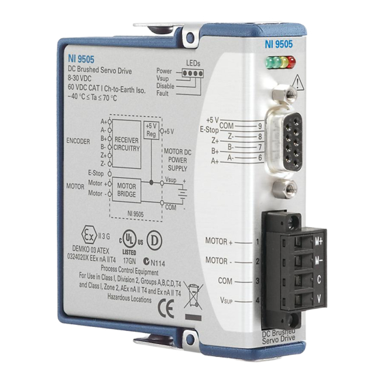
Specifications in normal mode. Refer to the section for more information about power consumption and thermal dissipation. NI 9505 Operating Instructions and Specifications | © National Instruments | 15... - Page 16 Wiring the NI 9505 The NI 9505 has a 9-pin female DSUB connector that provides connections for the encoder inputs, a +5 V connection for encoder power, a connection for an emergency stop input, and a connection to COM.
- Page 17 Encoder Index- (Phase Z-) Common (COM) Table 2. NI 9505 Screw Terminal Terminal Assignments Module Terminal Signal MOTOR+ MOTOR- M– COM (motor DC power supply reference) VSUP (motor DC power supply) NI 9505 Operating Instructions and Specifications | © National Instruments | 17...
- Page 18 Figure 4 shows a typical NI 9505 connection example, including encoder and E-Stop inputs. Figure 4. NI 9505 Connections Phase A± Encoder Phase B± Feedback Index± +5 V +24 V E-Stop Shield Motor M– Shield Motor DC Power Supply NI 9505...
- Page 19 National Instruments sales representative. Refer to the Specifications section for more information. Refer to Figure 5 for an illustration. Figure 5. NI 9505 Module with Optional Screw Terminal Accessory NI 9505 Operating Instructions and Specifications | © National Instruments | 19...
- Page 20 National Instruments recommends using ferrules to terminate wires to the detachable screw terminal connector or the NI 9931 Screw Terminal Accessory when you use the NI 9505 in high vibration applications. Refer to Figure 6 for an illustration. Figure 6. 4-Terminal Screw Terminal Connector or...
-
Page 21: Encoder Signals
Phase A, Phase B, and Index (Phase Z) signals. Figures 8 and 9 show simplified schematic diagrams of the encoder input circuit connected to differential and single-ended inputs. You can also accommodate open-collector output encoders NI 9505 Operating Instructions and Specifications | © National Instruments | 21... - Page 22 Refer to the examples installed at CompactRIO\Module Specific\NI 9505 for examples of using the encoder signals. Refer to the NI 9505 Reference Help book in the LabVIEW Help, available by selecting Help»Search the LabVIEW Help, for more information. If the encoder cable length is greater than 3.05 m (10 ft), use encoders with differential line driver outputs for your applications.
- Page 23 +5 V Phase + +5 V Encoder Receiver Phase – Figure 9. Single-Ended Encoder Input Circuit Encoder NI 9505 +5 V Encoder Signal +5 V Encoder Receiver No Connection NI 9505 Operating Instructions and Specifications | © National Instruments | 23...
- Page 24 FPGA or swap the Phase A and Phase B connections. When connecting the encoder wiring to the NI 9505, use shielded wire of at least 24 AWG. You must use cables with twisted pairs and an overall shield for improved noise immunity.
-
Page 25: Emergency Stop Signal
Search the LabVIEW Help, for information about how to enable this signal using the Enable E-Stop Property. Figure 10. Emergency Stop Input Circuit +24 V +3.3 V E-Stop E-Stop Optocoupler NI 9505 NI 9505 Operating Instructions and Specifications | © National Instruments | 25... - Page 26 Route wires along the machine frame to reduce high frequency noise. • Add clamp-on ferrites to cables to further reduce emissions. • Add a balun to the power cable to attenuate conducted and radiated emissions. 26 | ni.com | NI 9505 Operating Instructions and Specifications...
-
Page 27: Specifications
(Motor±) ........... 1 A @ 70 ºC 5 A @ 40 ºC For more information about maximum continuous current at temperatures less than 70 ºC, visit ni.com/info and enter rdmot2. NI 9505 Operating Instructions and Specifications | © National Instruments | 27... - Page 28 Current loop ADC resolution ......12 bits Current range......±12.7 A Maximum update rate....20 µs Minimum inductance ......500 µH Allow at least 3.4 s between peak current intervals. 28 | ni.com | NI 9505 Operating Instructions and Specifications...
-
Page 29: Drive Protection
Reverse polarity ........ -30 V Motor terminal (MOTOR±) short to ground........Yes Motor terminal (MOTOR±) short to VSUP ........Yes Temperature fault trip point ....115 ºC (internal module temperature) NI 9505 Operating Instructions and Specifications | © National Instruments | 29... -
Page 30: E-Stop Input
Maximum quadrature frequency..5 MHz E-Stop Input Input voltage range ......0 to 30 V Input ON voltage......3.5 to 30 V Input OFF voltage ...... 0 to 2 V 30 | ni.com | NI 9505 Operating Instructions and Specifications... -
Page 31: Power Requirements
If you need to clean the module, wipe it with a dry towel. For two-dimensional drawings and three-dimensional Note models of the C Series module and connectors, visit ni.com/dimensions and search by module number. NI 9505 Operating Instructions and Specifications | © National Instruments | 31... - Page 32 Securement type ......Screw flanges provided Torque for screw flanges .... 0.2N · m (1.80 lb · in.) Weight..........155 g (5.5 oz) Safety Safety Voltages Connect only voltages that are within the following limits. 32 | ni.com | NI 9505 Operating Instructions and Specifications...
- Page 33 Do not connect the NI 9505 to signals or use for Caution measurements within Measurement Categories II, III, or IV. NI 9505 Operating Instructions and Specifications | © National Instruments | 33...
-
Page 34: Hazardous Locations
IEC 61010-1, EN 61010-1 • UL 61010-1, CSA 61010-1 • EN 60079-0:2012, EN 60079-15:2010 • IEC 60079-0: Ed 6, IEC 60079-15; Ed 4 • UL 60079-0; Ed 5, UL 60079-15; Ed 3 34 | ni.com | NI 9505 Operating Instructions and Specifications... -
Page 35: Electromagnetic Compatibility
For the standards applied to assess the EMC of this Note Online Product Certification product, refer to the section. For EMC compliance, operate this device with Note shielded cabling. NI 9505 Operating Instructions and Specifications | © National Instruments | 35... -
Page 36: Online Product Certification
Operating vibration Random (IEC 60068-2-64)..5 g , 10 to 500 Hz Sinusoidal (IEC 60068-2-6) ..5 g, 10 to 500 Hz 36 | ni.com | NI 9505 Operating Instructions and Specifications... - Page 37 Operating humidity (IEC 60068-2-56)......10 to 90% RH, noncondensing Storage humidity (IEC 60068-2-56)......5 to 95% RH, noncondensing Maximum altitude......2,000 m Pollution Degree (IEC 60664) ..2 NI 9505 Operating Instructions and Specifications | © National Instruments | 37...
-
Page 38: Environmental Management
WEEE recycling center. For more information about WEEE recycling centers, National Instruments WEEE initiatives, and compliance with WEEE Directive 2002/96/EC on Waste and Electronic ni.com/environment/weee Equipment, visit 38 | ni.com | NI 9505 Operating Instructions and Specifications... -
Page 39: Worldwide Support And Services
NI. A Declaration of Conformity (DoC) is our claim of compliance with the Council of the European Communities using the manufacturer’s declaration of conformity. This system affords the NI 9505 Operating Instructions and Specifications | © National Instruments | 39... - Page 40 For patents covering National Instruments products/technology, refer to the appropriate location: Help»Patents in your software, the patents.txt file on your media, or the National Instruments Patent Notice at ni.com/patents . You can find information about end-user license agreements (EULAs) and third-party legal notices in the readme file for your NI product.
Need help?
Do you have a question about the NI 9505 and is the answer not in the manual?
Questions and answers