
Related Manuals for C&T Solution CT-XRL02


Summary of Contents for C&T Solution CT-XRL02
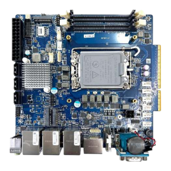
- Page 1 CT-XRL02 Mini-ITX Industrial Motherboard with LGA 1700 Socket supporting /13th/14th Gen Intel® Intel Alder Lake-S / Raptor Lake-S i9/i7/i5/i3 Core® /Pentium® /Celeron® IOTG Series Processors, Q670E Chipset...
- Page 2 CT-XRL02 l User’s Manual Table of Contents Prefaces …………………………………………………….……………………………………………. 03 Regulatory Notices …………….…………………………………………………………..……………….……….. 03 Safety Information …………………………..……………..…….…….………………………….……………….. 05 Technical Support and Assistance …………………………………….…………….…………….………….. 06 Conventions Used in this Manual ………………………………………………………………….….………. 06 Chapter 1 Product Introductions ………………………………………………………..… 07 Product Description ……….………………………………..………….………………..………. 08 Block Diagram……….………………………………..………….………………..………………….
- Page 3 Preface CT-XRL02 l User’s Manual Prefaces Revision Revision Description Date Initial release 2024/11/13 Regulatory Notices ⚫ FCC - Class A Radio Frequency Interference Statement This equipment has been tested and found to comply with the limits for a Class A digital device, pursuant to part 15 of the FCC rules.
- Page 4 Preface CT-XRL02 l User’s Manual ⚫ Battery Information Please take special precautions if this product comes with a battery. • Danger of explosion if battery is incorrectly replaced. Replace only with the same or equivalent type recommended by the manufacturer.
- Page 5 Preface CT-XRL02 l User’s Manual Safety Information • The components included in this package are prone to damage from electrostatic discharge (ESD). Please adhere to the following instructions to ensure successful computer assembly. • Ensure that all components are securely connected. Loose connections may cause the computer to not recognize a component or fail to start.
- Page 6 Preface CT-XRL02 l User’s Manual Technical Support and Assistance 1. Visit the C&T Solution Inc website at https://www.candtsolution.com where you can find the latest information about the product. 2. Contact your distributors, our technical support team or sales representative for technical support if you need additional assistance.
- Page 7 Chapter 1 Product Introductions...
- Page 8 CT-XRL02 l User’s Manual Chapter 1: Product Introductions 1.1 Product Description The CT-XRL02 Mini-ITX Industrial Motherboard with LGA 1700 Socket supporting 12th/13th/14th Gen Intel® Alder Lake-S/Raptor Lake-S i9/i7/i5/i3 Core®/Pentium®/ Celeron® IOTG Series Processors, Q670E Chipset...
- Page 9 CT-XRL02 l User’s Manual Appendix – Block Diagram CT-XRL02 Block Diagram...
- Page 10 CT-XRL02 l User’s Manual Chapter 1: Product Introductions 1.2 Specifications Form factor Mini-ITX • 13th/14th Gen Intel® Raptor Lake-S i9/i7/i5/i3 Core®/Pentium®/ Celeron® IOTG Series Processor, Max 65W - 1.6 GHz~5.1 GHz (depends on CPU) - Socket LGA 1700 Processor • 12th Gen Intel® Alder Lake-S i9/i7/i5/i3 Core®/Pentium®/ Celeron® IOTG Series Processor, Max - 1.6 GHz~5.1 GHz (depends on CPU)
- Page 11 CT-XRL02 l User’s Manual Chapter 1: Product Introductions • 1 x 24-pin ATX power connector Power • 1 x 4-pin 12V CPU power connector • 1 x 4-pin PWM CPU fan connector Cooling • 6 x 4-pin PWM system fan connectors •...
- Page 12 Chapter 2 Mechanical Specifications...
- Page 13 CT-XRL02 l User’s Manual Chapter 2: Mechanical Specifications 2.1 Switch and Connector Locations Top View M2_B1 SYSFAN1 JFP1 DIMM2 DIMM1 JUSIM1 JUSB2 (SKU1,2 Only) JPWR1 JSATA1 PCIE1 JSATA3 JSATA2 JAMP1 JAUD1 JPWR3 M2_E1 M2_M1 JCOM3_4 JBAT1...
- Page 14 CT-XRL02 l User’s Manual Chapter 2: Mechanical Specifications Rear I/O Panel RJ-45 LAN Jacks Line-Out COM2 Jack HDMI LAN_USB1 LAN_USB2 LAN_USB3 DP_1/2 Mic-in COM1 USB 3.2 Gen2 Ports Jack DisplayPorts RS232/422/485 Serial Ports...
- Page 15 CT-XRL02 l User’s Manual Chapter 2: Mechanical Specifications • Line-Out Jack This connector is provided for external headphones or speakers. • Mic-In Jack This connector is provided for external microphones. • 2.5 GbE RJ-45 LAN Jacks Three standard single RJ45 LAN jacks are provided for connections to the Local Area Network (LAN).
- Page 16 CT-XRL02 l User’s Manual Chapter 2: Mechanical Specifications • RS232/422/485 Serial Port The serial port is a 16550A high speed communication port that sends/receives 16 bytes FIFOs. It supports barcode scanners, barcode printers, bill printers, credit card machine, etc. RS232...
- Page 17 CT-XRL02 l User’s Manual Chapter 2: Mechanical Specifications 2.2 Connector / Switch Definition Component 2.2 CPU Socket 2.3 CPU & Heatsink Installation 2.4 Memory • DIMM1~2: DDR4 SO DIMM Slots 2.5 Storage • JSATA1: SATA 3.0 6Gb/s Ports • M2_M1: M.2 Slot (M Key, 2242, 2280) 2.6 Expansion Slots...
- Page 18 CT-XRL02 l User’s Manual Chapter 2: Mechanical Specifications 2.3 I/O Interface Descriptions 2.3.1 CPU Socket • Introduction to the LGA1700 CPU The surface of the LGA1700 CPU has four notches and a golden triangle to assist in correctly lining up the CPU for motherboard placement. The golden triangle is the Pin 1 indicator.
- Page 19 CT-XRL02 l User’s Manual Chapter 2: Mechanical Specifications • CPU & Heatsink Installation Use appropriate ground straps, gloves and ESD mats to protect yourself from electrostatic discharge (ESD) while installing the processor. • Important Images are for illustration purposes only; actual parts may vary.
- Page 20 CT-XRL02 l User’s Manual Chapter 2: Mechanical Specifications 2.3.2 Memory DIMM1 DIMM2 • DIMM1~2: DDR4 SO DIMM Slots The SO-DIMM slots are intended for memory modules. 1. Open the side clips to unlock the DIMM slot. 2. Insert the DIMM vertically into the slot, ensuring that the off-center notch at the bottom aligns with the slot.
- Page 21 CT-XRL02 l User’s Manual Chapter 2: Mechanical Specifications 2.3.3 Storage JSATA2 JSATA3 JSATA1 • JSATA1: SATA 3.0 6Gb/s Ports This connector is SATA 6Gb/s interface port, it can connect to one SATA device. • Important • This SATA port supports hot plug.
- Page 22 CT-XRL02 l User’s Manual Chapter 2: Mechanical Specifications 2.3.4 M2_M1: M.2 Slot (M Key, 2242, 2280) Please install the M.2 solid-state drive (SSD) into the M.2 slot as shown below. • Video Demonstration Watch the video to learn how to Install M.2 SSD.
- Page 23 CT-XRL02 l User’s Manual Chapter 2: Mechanical Specifications 2.3.5 Expansion Slots Please install the M.2 solid-state drive (SSD) into the M.2 slot as shown below. M2_B1 (Nano SIM) PCIe X16 Gen4 (200-Pin Gold Fingers) for Risers M2_E1 • PCIE1: PCIe Expansion Slots The PCI Express(Peripheral Component Interconnect Express) slots support PCIe interface expansion cards.
- Page 24 CT-XRL02 l User’s Manual Chapter 2: Mechanical Specifications • M2_E1: M.2 Slot (E Key, 2230) Please install the Wi-Fi/ Bluetooth card into the M.2 slot as shown below. Feature • Supports PCIe x 1 & USB 2.0 signal. • Supports CNVi.
- Page 25 CT-XRL02 l User’s Manual Chapter 2: Mechanical Specifications 2.3.6 Connectors Power Connectors JPWR1 JPWR3 • JPWR1: ATX 24-Pin Power Connector This connector allows you to connect an ATX power supply. +3.3V +3.3V PWROK 5VSB +12V +12V +3.3V +3.3V -12V P-ON# •...
- Page 26 CT-XRL02 l User’s Manual Chapter 2: Mechanical Specifications Audio Connectors JAU D 1 JAUD1: Front Audio Header This connector allows you to connect front panel audio. MIC_L MIC_R PRESENCE# F_OUTR MIC2_JD HP ON Nopin F_OUTL LIN2_JD...
- Page 27 CT-XRL02 l User’s Manual Chapter 2: Mechanical Specifications 2.3.7 Other Connectors CPUFAN1 SYSFAN 1_6 • CPUFAN1, SYSFAN1_6: CPU/ System Fan Box Headers The fan power connector supports CPU/ system cooling fans with +12V. When connecting the wire to the connectors, always note that the red wire is the positive and should be connected to the +12V;...
- Page 28 CT-XRL02 l User’s Manual Chapter 2: Mechanical Specifications • JFP1: Front Panel Connector This front-panel connector is provided for electrical connection to the front panel switches & LEDs and is compliant with Intel Front Panel I/O Connectivity Design Guide. JFP1...
- Page 29 CT-XRL02 l User’s Manual Chapter 2: Mechanical Specifications • JCOM3_4: COM Port Box Header This connector is a 16550A high speed communications port that sends/ receives 16 bytes FIFOs. You can attach a serial device to it. JCOM3_4 NDCD3# NDCD4#...
- Page 30 CT-XRL02 l User’s Manual Chapter 2: Mechanical Specifications Feature RS232 • Support True RS-232 SIGNAL DESCRIPTION • Support TTL RS-232 NDCD Data Carrier Detect • Support Auto flow control NSIN Signal In • RS- 422/ 485 support TR 1000+ Meter...
- Page 31 CT-XRL02 l User’s Manual Chapter 2: Mechanical Specifications • JGPIO1: GPIO (DIO) Box Header This connector is provided for the General-Purpose Input/Output (GPIO) peripheral module. JI2C1 JGPIO1 JGPIO1 N_GPO0 N_GPI0 N_GPO1 N_GPI1 N_GPO2 N_GPI2 N_GPO3 N_GPI3 N_GPO4 N_GPI4 N_GPO5 N_GPI5...
- Page 32 CT-XRL02 l User’s Manual Chapter 2: Mechanical Specifications • JUSB1: USB 2.0 Box Header These connectors are ideal for connecting USB devices such as keyboard, mouse, or other USB- compatible devices. JUSB2 JUSB1 JUSB1 USB_D- USB_D- USB_D+ USB_D+ No pin •...
- Page 33 CT-XRL02 l User’s Manual Chapter 2: Mechanical Specifications • JBAT1: CMOS Battery Header If the CMOS battery is out of charge, the time in the BIOS will be reset and the data of system configuration will be lost. In this case, you need to replace the CMOS battery.
- Page 34 CT-XRL02 l User’s Manual Chapter 2: Mechanical Specifications 2.3.8 Jumpers JCASE5 JAUD1 • Important Avoid adjusting jumpers when the system is on; it will damage the motherboard. Jumper Name Default Setting Description COM Voltage Select Jumper 1-2: 5V Power JCOMP1...
- Page 35 CT-XRL02 l User’s Manual Chapter 2: Mechanical Specifications Jumper Name Default Setting Description AT/ ATX Mode Select Jumper JATX1 1-2: ATX (Default) 2-3: AT LVDS Power Jumper JVDD1 1-2: 3.3V (Default) 2-3: 5V Chassis Intrusion Jumper This connector connects to the chassis intrusion switch cable.
- Page 36 Chapter 3 System BIOS...
- Page 37 CT-XRL02 l User’s Manual Chapter 3: BIOS Setup 3.1 BIOS Introduction This chapter provides information on the BIOS Setup program and allows users to configure the system for optimal use. BIOS Setup Users may need to run the Setup program when: •...
- Page 38 CT-XRL02 l User’s Manual Chapter 3: BIOS Setup Control Keys ← → Select Screen ↑ ↓ Select Item Enter Select Change Value Exit General Help Previous Values Optimized Defaults Save & Reset* Screenshot capture <K> Scroll help area upwards <M>...
- Page 39 CT-XRL02 l User’s Manual Chapter 3: BIOS Setup 3.2 The Menu Bar Press <Del> to enter BIOS CMOS Setup Utility. The Main setup screen is showed as following when the setup utility is entered. System Date/Time is set up in the Main Menu.
- Page 40 CT-XRL02 l User’s Manual Chapter 3: BIOS Setup 3.3 Main ∙ HDD Information ∙ RAID (VMD) Disabled: Display HDD information as plugging in status. RAID (VMD) Enabled: Display "Not Present" only. ◼ System Date This setting allows you to set the system date.
- Page 41 CT-XRL02 l User’s Manual Chapter 3: BIOS Setup 3.4 Advanced ◼ Full Screen Logo Display This BIOS feature determines if the BIOS should hide the normal POST messages with the motherboard or system manufacturer’s full-screen logo. BIOS will display the full-screen logo during the boot-up sequence, hiding [Enabled] normal POST messages.
- Page 42 CT-XRL02 l User’s Manual Chapter 3: BIOS Setup CPU Configuration ◼ Intel Virtualization Technology Enables or disables Intel Virtualization technology. Enables Intel Virtualization technology and allows a platform to run multiple [Enabled] operating systems in independent partitions. The system can function as multiple systems virtually.
- Page 43 CT-XRL02 l User’s Manual Chapter 3: BIOS Setup ◼ Intel(R) Speed Shift Technology Intel® Speed Shift Technology is an energy-efficient method that allows frequency control by hardware rather than the OS. When enabled, Intel® Speed Shift Technology is activated. The technology...
- Page 44 CT-XRL02 l User’s Manual Chapter 3: BIOS Setup Super IO Configuration ◼ Serial Port 1/ 2/ 3/ 4 This setting enables or disables the specified serial port. » Change Settings This setting is used to change the address & IRQ settings of the specified serial port.
- Page 45 CT-XRL02 l User’s Manual Chapter 3: BIOS Setup H/W Monitor (PC Health Status) These items display the status of all monitored hardware devices/ components such as voltages, temperatures and all fans’ speeds.. ◼ Thermal Shutdown This setting determines the behavior of the system when the CPU temperature reaches a predefined threshold.
- Page 46 CT-XRL02 l User’s Manual Chapter 3: BIOS Setup PCI/PCIE Device Configuration These items display the status of all monitored hardware devices/ components such as voltages, temperatures and all fans’ speeds.. ◼ Audio Controller This setting enables or disables the detection of the onboard audio controller.
- Page 47 CT-XRL02 l User’s Manual Chapter 3: BIOS Setup GPIO Group Configuration ◼ GPO0 ~ GPO7 These settings control the operation mode of the specified GPIO. Intel(R) RST Enables or disables Intel® RST. Intel® Rapid Storage Technology (Intel® RST) is a feature that combines the capabilities of both hardware and software to enhance storage performance, data protection, and flexibility.
- Page 48 CT-XRL02 l User’s Manual Chapter 3: BIOS Setup PCIE ASPM settings This menu provides settings for PCIe ASPM (Active State Power Management) level for different installed devices. ◼ M2_B1/ M2_E1/ M2_M1/ PCIE1 Sets PCI Express ASPM (Active State Power Management) state for power saving.
- Page 49 CT-XRL02 l User’s Manual Chapter 3: BIOS Setup 3.5 Boot ◼ Boot Option #1-2 This setting allows users to set the sequence of boot devices where BIOS attempts to load the disk operating system.
- Page 50 CT-XRL02 l User’s Manual Chapter 3: BIOS Setup 3.6 Security ◼ Administrator Password Administrator Password controls access to the BIOS Setup utility. ◼ User Password User Password controls access to the system at boot and to the BIOS Setup utility.
- Page 51 CT-XRL02 l User’s Manual Chapter 3: BIOS Setup PCH-FW Configuration This menu allows you to configure settings related to the PCH firmware. Firmware Information These settings show the ME Firmware Version ME Firmware SKU firmware information of the Intel ME (Management...
- Page 52 CT-XRL02 l User’s Manual Chapter 3: BIOS Setup Firmware Update Configuration » ME FW Image Re-Flash Enables or disables the ME Firmware Image Re-flashing. » Local FW Update Enables or disables the capability to perform a firmware update of the ME locally.
- Page 53 CT-XRL02 l User’s Manual Chapter 3: BIOS Setup ME Debug Configuration This menu allows you to configure debug-related options for the Intel® Management Engine (ME). » HECI Timeouts This setting enables/ disables the HECI (Host Embedded Controller Interface) send/ receive timeouts.
- Page 54 CT-XRL02 l User’s Manual Chapter 3: BIOS Setup Anti-Rollback SVN Configuration » Automatic HW-Enforced Anti-Rollback SVN Setting this item enables will automatically activate the hardware-enforced anti-rollback protection based on the Secure Version Number (SVN). Once enabled, the hardware will enforce that only firmware updates with an SVN equal to or higher than the current SVN can be installed.
- Page 55 CT-XRL02 l User’s Manual Chapter 3: BIOS Setup AMT Configuration Intel® Active Management Technology (Intel® AMT) is hardware-based technology for remotely managing and securing PCs out-of-band (OOB). ◼ USB Provisioning of AMT Enables or disables the ability to provision AMT using a USB device.
- Page 56 CT-XRL02 l User’s Manual Chapter 3: BIOS Setup Secure Erase Configuration » Secure Erase Mode This setting changes Secure Erase module behavior. [Simulated] Performs SE flow without erasing SSD. [Real] Erase SSD. » Force Secure Erase Enables or disables to force Secure Erase on next boot.
- Page 57 CT-XRL02 l User’s Manual Chapter 3: BIOS Setup » Intel(R) AMT Configuration » Redirection features • SOL Enables or disables SOL (Serial Over LAN). • Storage Redirection Enables or disables Storage Redirection. • KVM Feature Selection Enables or disables the ability to remotely control a system’s keyboard, video, and mouse (KVM) by a distant management console.
- Page 58 CT-XRL02 l User’s Manual Chapter 3: BIOS Setup » Password Policy This feature determines when the user is allowed to change the Intel® MEBX password through the network. [Default Allows changing the Intel® MEBx password through the network interface only if the default password has not been changed yet.
- Page 59 CT-XRL02 l User’s Manual Chapter 3: BIOS Setup • TCP/IP Settings • Wired Lan IPV4 Configuration • DHCP Mode Enables or disables the DHCP (Dynamic Host Configuration Protocol) mode. The items shown above will display when DHCP Mode is set to disabled.
- Page 60 CT-XRL02 l User’s Manual Chapter 3: BIOS Setup » Power control This menu configures the Intel ME platform power-related policies, and the configurations are effective only after ME provisioning has started. • One Click Recovery (OCR) Configuration » OCR Https Boot Enables or disables the use of HTTPS (Hypertext Transfer Protocol Secure) for the OCR boot process.
- Page 61 CT-XRL02 l User’s Manual Chapter 3: BIOS Setup • Remote Platform Erase Configuration Intel® Remote Platform Erase (Intel® RPE) Configuration provides settings for the remote erasure of the platform information or specific storage devices connected to the system. » Enable Remote Platform Erase Feature Enables or disables the ability to initiate the remote erasure process for the system or selected storage devices.
- Page 62 CT-XRL02 l User’s Manual Chapter 3: BIOS Setup Trusted Computing ◼ Security Device Support This item enables or disables BIOS support for security device. When set to [Disable], the OS will not show security device. ◼ SHA256 PCR Bank These settings enable or disable the SHA-1 PCR Bank and SHA256 PCR Bank.
- Page 63 CT-XRL02 l User’s Manual Chapter 3: BIOS Setup Serial Port Console Redirection ◼ Console Redirection Console Redirection operates in host systems that do not have a monitor and keyboard attached. This setting enables or disables the operation of console redirection. When set to [Enabled], BIOS redirects and sends all contents that should be displayed on the screen to the serial COM port for display on the terminal screen.
- Page 64 CT-XRL02 l User’s Manual Chapter 3: BIOS Setup » Bits per second, Data Bits, Parity, Stop Bits These settings specify the transfer rate (bits per second, data bits, parity, stop bits) of Console Redirection. » Flow Control Flow control is the process of managing the rate of data transmission between two nodes. It’s the process of adjusting the flow of data from one device to another to ensure that the receiving device can handle all of the incoming data.
- Page 65 CT-XRL02 l User’s Manual Chapter 3: BIOS Setup 3.7 Secure Boot • Secure Boot Secure Boot function can be enabled only when the Platform Key (PK) is enrolled and running accordingly. • Secure Boot Mode Select the secure boot mode. This item appears when Secure Boot is enabled.
- Page 66 CT-XRL02 l User’s Manual Chapter 3: BIOS Setup » Platform Key (PK): The Platform Key (PK) can protect the firmware from any un-authenticated changes. The system will verify the PK before your system enters the OS. Platform Key (PK) is used for updating KEK.
- Page 67 CT-XRL02 l User’s Manual Chapter 3: BIOS Setup » Delete Key Deletes the db from your system. » Forbidden Signatures (dbx): Forbidden Signatures (dbx) lists the forbidden signatures that are not trusted and cannot be loaded. » Set New Key Sets a new dbx to your system.
- Page 68 CT-XRL02 l User’s Manual Chapter 3: BIOS Setup 3.8 Chipset • DVMT Total Gfx Mem This setting specifies the total graphics memory size for Dynamic Video Memory Technology (DVMT). • Panel Select Set your video signal interface as LVDs or eDP.
- Page 69 CT-XRL02 l User’s Manual Chapter 3: BIOS Setup 3.9 Power • Restore AC Power Loss This setting specifies whether your system will reboot after a power failure or interrupt occurs. Available settings are: [Power Off] Leaves the computer in the power off state.
- Page 70 CT-XRL02 l User’s Manual Chapter 3: BIOS Setup 3.10 Save & Exit • Save Changes and Reset Save changes to CMOS and reset the system. • Discard Changes and Exit Abandon all changes and exit the Setup Utility. • Discard Changes Abandon all changes.
- Page 71 Appendix GPIO WDT BKL Programming Block Diagram This chapter provides WDT (Watch Dog Timer), GPIO (General Purpose Input/ Output) and CT-XRL02 Block Diagram...
- Page 72 Appendix – WDT & GPIO CT-XRL02 l User’s Manual Abstract In this section, code examples based on C programming language are provided for customer interest. Inportb, Outportb, Inportl and Outportl are basic functions used for access IO ports and defined as following.
- Page 73 Appendix – WDT & GPIO CT-XRL02 l User’s Manual General Purpose IO 1. General Purposed IO – GPIO/DIO The GPIO port configuration addresses are listed in the following table: Name IO Port IO address Name IO Port IO address N_GPI0...
- Page 74 Appendix – WDT & GPIO CT-XRL02 l User’s Manual 1.2 Read input value from GPI: 1. Read the value from GPI port. 2. Get the value of GPI address. Example: Get N_GPI2 input value. val = SMBus_ReadByte (0x6E, 0x22); // Read value from N_GPI2 port through SMBus.
- Page 75 CT-XRL02 l User’s Manual Appendix – WDT & GPIO Watchdog Timer 2. Watchdog Timer – WDT The base address (WDT_BASE) of WDT configuration registers is 0xA10.2. 2.1 Set WDT Time Unit val = Inportb (WDT_BASE + 0x05); // Read current WDT setting val = val | 0x08;...
- Page 76 CT-XRL02 l User’s Manual Appendix – WDT & GPIO SMBus Access 4. SMBus Access The base address of SMBus must know before access. The relevant bus and device information are as following. #define IO_SC 0xCF8 #define IO_DA 0xCFC #define PCIBASEADDRESS...
- Page 77 Copyright © C&T Solution Inc. All Rights Reserved www.candtsolution.com...
Need help?
Do you have a question about the CT-XRL02 and is the answer not in the manual?
Questions and answers