
Related Manuals for Scaime IPE 50 P


Summary of Contents for Scaime IPE 50 P
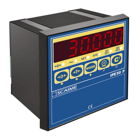
- Page 1 WEIGHING INDICATOR IPE 50 P USER MANUAL (valid from version 5.01) SCAIME SAS Tél : +33 4 50 87 78 64 BP501 Fax : +33 4 50 87 78 46 F 74105 ANNEMASSE www.scaime.com...
- Page 2 IPE50P INDEX 1 INTRODUCTION......................page 2 2 MAIN TECHNICAL SPECIFICATIONS ................page 3 3 DIMENSIONS ........................page 4 4 POWER SUPPLY & START-UP..................page 5 5 FRONT PANEL KEYS AND INDICATORS ..............page 5 6 BASIC FUNCTIONS ......................page 7 7 SELECTABLE OPERATING MODES ................page 11 8 INSTRUMENT MESSAGES WHILE IN USE ..............page 19 9 PRINTING EXAMPLES ....................page 20...
- Page 3 IPE50P 1 INTRODUCTION The purpose of this manual is to help the user get to know the weight indicator’s various functioning modes, the keys’ functions and the display indications We advise to carefully follow the instructions for programming the weight indicator; by taking actions not indicated this manual, one could cause the scale to not work properly.
- Page 4 IPE50P 2 MAIN TECHNICAL SPECIFICATIONS POWER SUPPLY 12 to 24Vdc / 3.6 W max OPERATING TEMPERATURE From -10 to +40 °C (14 to 104 °F). DISPLAYED DIVISIONS 10000e, 2X3000e for legal for trade use expandable to 800.000 for internal use (with minimum signal coming from the 1,6mV/V cell).
- Page 5 IPE50P 3 DIMENSIONS 1 and 2 Connection of power supply (12 to 24Vdc) connection of the 2 inputs, the contact of setpoints and RS232 and 485 connection of sensors connection of the 2 to 6 contact relays (6 relays in option)
- Page 6 IPE50P 4 POWER SUPPLY & START UP Do not connect other equipment to the same socket as the one that the adapter is in. Do not step on or crush the power supply cable The display shows in sequence: L.1.06 05.01 indicate the version of software if you press the key ->0<- 09.01...
- Page 7 IPE50P VOYANTS FONCTIONS Indicates that the weight detected on the weighing system is near zero, ->0<- within the interval of –1/4 to +1/4 of the division. Indicates that the weight is unstable. Indicates that the displayed weight is a net weight. Indique que l'IPE50P est dans un mode de fonctionnement particulier W1/ SP1 ou W1 or W2 show the functionning with 2 weighing ranges...
- Page 8 IPE50P 6 BASIC FUNCTIONS Nota : if the IPE50P has never calibrated, the message “Err 39” will be displayed (see page 50) Sometime it will be necessary to go to differents menus to modify some prameters. To enter into these menus , turn on the unit, L. 1.06 and after 05.01 are displayed, press the ->0<- key when 05.01 is displayed, after 09.01, DGT9 and the version of the software are displayed, press ->T<- key during the countdown the display shows the first parameter “TyPE”.
- Page 9 IPE50P With the UNLOCKED tare: In case of SEMIAUTOMATIC TARE the net weight, before unloading the scale, may also be 0. In case of MANUAL TARE or FROM DATABASE the net weight before unloading the scale must be of at least 2 stable divisions. To set the type of tare: - Select menu F.Mode.
- Page 10 IPE50P 6.5 DATE/TIME ADJUSTMENT (OPTIONAL) The indicator can be fitted with the date/time option; in this case, the “CLoCK” message is shown when instrument is turned on. To set the date/time follow the procedure below: Select menu F.Mode. Press ENTER to enter the menu. Press ->0<- many times (to scroll forwards through the parameters) or ->T<- (to scroll backwards) to find the “CLoCK”...
- Page 11 IPE50P 6.8 REENABLING THE PRINTOUTS AND THE INDICATOR FUNCTIONS While using the indicator, it is possible to incur into the “no.0.unS” error shown on the display along with an acoustic signal; this means that the printing or the function which one wants to carry out must be reenabled (in order to avoid unwanted executions).
- Page 12 IPE50P 7 SELECTABLE OPERATING MODES In addition to the STANDARD weighing mode with TARE deduction and transmission of data, the indicator can carry out one of the following functions: kg/lb CONVERSION, NET/GROSS SWITCH, SET POINT ON THE GROSS WEIGHT, SET POINT ON THE NET WEIGHT, IN/OUT, ALIBI, DISPLAY WITH SENSITIVITY X 10, HOLD THE DISPLAY, PEAK, HORIZONTAL TOTALIZER, VERTICAL TOTALIZER, and PIECE COUNTING.
- Page 13 IPE50P 7.1 kg/lb CONVERSION (Std) By pressing "MODE" key the value is converted from kg to lb and vice versa. NOTES: - with APPROVED instrument in single range the weight in pounds is displayed for 5 seconds, after which the display goes to kilograms.
- Page 14 IPE50P With a NON APPROVED scale one has a STABLE weight and GREATER than 0. With an APPROVED scale one has a STABLE weight and GREATER than 20 divisions. if the setting of the rEACt parameter in the set-up environment has been respected (passage by zero of the weight, instability, or always);...
- Page 15 IPE50P MAx.tot: NUMBER OF CONSECUTIVE TOTALISATIONS AFTER WHICH THE TOTAL IS AUTOMATICALLY PRINTED AND RESET After having carried out the set weighs, the accumulated general total is printed and reset; set a value between 00 and 63. NOTE: the value 00 disables the function TOTALISATION OPERATIONS In order to carry out the totalisation it is necessary to press the MODE key (if the automatic totalisation has not been set): the weight is accumulated in two total levels (a partial total and a general total).
- Page 16 IPE50P 7.8 VERTICAL TOTALIZER (Sum by recipe -> tot S) Like the horizontal totaliser but with each pressing of MODE (or automatcly depend of parameter rEACT) the indicated weight is totalised and automatically tared; in this way it is possible for example to fill a container with various products and to know the total weight of the container (on the display or/and on a printer) and the total weight of all the containers weighted (on the display or/and on a printer) .
- Page 17 IPE50P the quantity extracted. 5) Continue the counting in extraction. “Er.Mot” ERROR DUE TO WEIGHT INSTABILITY DURING THE SAMPLING It may happen that during the sampling phase the weight is unstable and therefore it is not possible to correctly calculate the APW. The “Er.Mot” is shown remaining for about three seconds. One should therefore repeat the sampling operation.
- Page 18 IPE50P option FunC : Functionning mode of the 2 setpoints (available for setpoint 1 to 6) 0 nonE : the setpoint is disable 1 GroS : setpoint on the gross display 2 nEt : setpoint on the net display 3 PCS : setpoint on the counting mode 4 Gro.O : the setpoint will be actionned when the display will be at 0 in gross value 5 nEt.O : the setpoint will be actionned when the display will be at 0 in net value 6 Moti.
- Page 19 IPE50P MODE WITH HYSTERESIS One enters two SET POINTS for each relay: a DISABLING one, which, when the gross weight is lower than it, it disables the concerned relay; and an ENABLING one, which, when the gross weight is equal or greater than it, it enables the concerned relay.
- Page 20 IPE50P 7.11 INPUT CONFIGURATION (for the 2 inputs remote control) In this step one sets the function to link to each input on the screw terminal nonE Disabled ZEro ->0<- Key tArE ->T<- Key ModE MODE Key EntEr ENTER Key diS.kEy DISABLING OF KEYBOARD (!) nonE...
- Page 21 IPE50P 9 PRINTING EXAMPLES GROSS 8,000 kg GROSS 1,228 kg 3,000 kg TARE 0,456 kg 5,000 kg 0,772 kg TICKET NR. 12:41 08-01-02 0,00514 kg TICKET NR. Indicator in Standard Mode 12:11 08-01-02 (UISS, Std, ntgS) Piece Counting Mode GROSS (HOLD) 4,664 kg WEIGHING NR.
- Page 22 IPE50P 10 INSTALLATION To obtain the best results it is recommended to install the indicator and the platform (or transducer) in a place with the following conditions: A flat, level surface on which to rest Stable and vibration free Moderate temperature and humidity (15-30°C and 40-70%). No dust or strong vapours No draughts Mains power supply is restricted to 12….
- Page 23 IPE50P 11 BLOCK DIAGRAM ntGS inout G. t., 1St.2nd, in.out Ind.Ch. , dEP.Ch. , SCALE, Pal.trK, tYPE tyPE MuL.SCA trAnSN. MAStr nuMSL (01...04) Alibi F.Mode FunCt. UiSS P 26 PEAk tot o tot.Mod norM.t, FASt.t, Auto MAx.tot tot S tot.Mod norM.t, FASt.t, Auto Max.tot Coun...
- Page 24 IPE50P Ch 1 to 4 nChAn FF.200. 1..3 ConFiG Param. Stabil. FLt 0..3 doS.0..3 FF.100. 1..4 h.r.0..7 dyn.0..3 SLW.0..5 FF.50. 1..3 EnAb , DiSab (*) Auto-0 Auto, FrEE (*) 0trACk ¼, ½, 1, 2, no diV.Stb. 0...19 (*) GrAV ZonE A, ZonE b, ZonE C, SiCi 2, AoStA, inSErt Calib (*) rAnGE 1 (*) rAnGE 2...
- Page 25 IPE50P CoM . Prn Pr ModE tPr, LP542P, ALL.Std, ALL.Ext, PrPC . St , PrPC . EX , rEPE.6, Pr-no bAud.Pr 1200, 2400, 4800, 9600, 19200, 38400 , 57600 , 115200 P 29 Bit.Pr n - 8 - 1, n - 8 - 2, n - 7 - 2, E - 7 - 1 , E - 7 - 2 PWr.Prn PWr.Ext, Ext.oFF Prn .CtS...
- Page 26 IPE50P Technical Personnel Only 12 SETUP ENVIRONMENT If the IPE50P has never been calibrated, the message Err 39 will be displayed (see page 50) With "SETUP ENVIRONMENT" we intend a specific menu, inside which it’s possible to set all the functioning parameters of the indicator.
- Page 27 IPE50P 12.1 DESCRIPTION OF THE STEPS TYPE Ind.Ch. always use this parameter DEP.Ch. TrAnSM. not operating F.ModE FunCt FUNCTIONING MODE kg / lb conversion. ntGS Net weight / gross weight conversion. inout Input / output weigh. MAStr Master to use with 1 to 4 slaves IPE50P ALibi Alibi memory (or DSD) UiSS...
- Page 28 IPE50P CLoCK DATE/TIME ADJUSTMENT (OPTIONAL) In this step one sets the date and time of the indicator; by pressing ENTER one is asked to enter, in this order, the day, month, year, hour and minute. The entry of each parameter must be confirmed with ENTER NOTE: the parameter is not displayed if there is no date/time option.
- Page 29 IPE50P (*) 0trACk ZERO TRACKING This menu allows setting the zero tracking, in other words, the compensation parameter of the scale’s thermal drift; the set value corresponds to the number of divisions that is reset in the fixed time of 1 second. tr.
- Page 30 IPE50P SeriAL (SERIALS, PRINTOUTS, ETC…) PC SEL SELECTION OF THE COMMUNICATION PORT BIDIRECTIONEL COM1 The serial output RS485 or RS232 (depends of the 3 jumpers selected on the printed circuit) is the output for the bidirectional communication with PC … COM2 The serial output 232 is the output for the bidirectional communication with PC …...
- Page 31 IPE50P PrConF CONFIGURATION OF THE PRINTOUTS See the “Print Programming” section for the description of all the menu’s parameters. NOTE: the parameter and all its submenus are not displayed if “Prno” has been selected in the “PWr.Prn” step or “Pr- no” in the “PrModE” step. CoM.PC TRANSMISSION bidirectional (COM1 or COM2 depend of the PC SEL choice) PCModE TRANSMISSION SERIAL OUTPUT ondE...
- Page 32 IPE50P inPutS INPUT CONFIGURATION In this step one sets the function to link to each input inP.b1 INPUT 1 nonE Disabled ZEro ->0<- Key tArE ->T<- Key ModE MODE Key EntEr ENTER Key diS.kEy DISABLING OF KEYBOARD (!) nonE inP.b2: INPUT 2 The programming of the inputs 2 is done as described for input 1.
- Page 33 IPE50P DELAY : Select a time (from 0.0 to 100.0 seconds) of delay that the relays could not be on (even the display is upper than the setpoint value) after this delay, le relay could be on (if the display is upper than the setpoint value).
- Page 34 IPE50P diSPLA DISPLAY TEST By pressing ENTER the instrument turns on all the display segments one at a time, after which it exits automatically from the step. KEYb. KEYBOARD TEST By pressing ENTER the instrument displays 0000; by pressing the keys one at a time, the relative codes are rebrought to the display.
- Page 35 IPE50P 13 ADJUSTMENT Nota : if the IPE50P has never been calibrated, the message “Err 39” will be displayed, press the key ->T<- to enter into the menus. SEtuP ConFiG nChan 1, 2, 3, 4 Chan Ch1, Ch2, Ch3, Ch4 (*) GrAV Calib (*) rAnGE 1...
- Page 36 IPE50P 3) NChAn is displayed, press ENTER -> Ch 1, keep this choice. 4) ParAM is displayed, choose CALib with key ->0<- and press ENTER. 5) “rAnGE1” is displayed, press ENTER The position of the decimal point will be set later, step dECI Set the total capacity of the scale or the first range in case of multirange functioning (ex: 002.000 it means maximal display is 2.000).The displayed could display until this value set, after the display shows "¯...
- Page 37 IPE50P Quick adjustment of the zero If the tare of the system has changed, you could anly memorize a "new zero". Select the step "0.CAL" in the menu SETup -> ConFiG -> 0.CAL (see paragraph 13 adjustment ). When 0.CAL is displayed, press ENTER, "CAL.0" is displayed. The system is at zero (without load).
- Page 38 IPE50P 13.1 ANALOG OUTPUT This IPE50P has an analog output (0/10V or/and 4/20mA) which is automatically calibrated for the higher value (10V or 20mA) of the max capacity selected in rAnGE 1.These outputs correspond to the displayed value. You must adjust this output through the step AoMAX and AoZEr (see step after) It works only on a positive display if the step SiGn = PoSit (if the display is negative, the output will be the minimum value set at Ao ZEr step), It works only on a negative display if the step SiGn = nEGAt (if the display is positive, the output will be the minimum value set Ao ZEr step).
- Page 39 IPE50P 13.2 IN CASE THE ZONE OF USE IS DIFFERENT FROM THE CALIBRATION ZONE ONE SHOULD: 1) Enter in the SET-UP environment of the scale (when turned on, press for an instant the TARE or the ZERO key during the countdown). 2) Enter in the SEtuP →...
- Page 40 IPE50P The instrument communicates the weight data through the serial port when the ENTERkey is pressed (except for in the TOTALIZER mode where one should press the MODE key). For non approved instruments: The transmission takes place if the weight is stable and the net weight is > 0. Reenabling the transmission depends on how the “rEACt”...
- Page 41 IPE50P 14.2 SERIAL PORT RS232 and 485 (unidirectional) It is unidirectional (halfduplex) , it is mainly used to connect to printers, repeater …… The choice of RS232 or 485, is made by the parameter SEL PC, this other port will be bidirectional. Please find below the various selectable serial weight transmission modes of the PC serial port through the corresponding “PCModE”...
- Page 42 IPE50P [CC]MVOL<CR LF> Instrument response: STANDARD STRING : ex : ST,VT, 5.001,mV Reading command of converter points relative to the weight [CC]RAZF<CR LF> Instrument response: STANDARD STRING . ST,RZ, 2018206,vv Nota: If the IPE is configurated in mode IND.Ch, and at least 2 channels are connected (on channel 1 and 2) le sensor signal transmitted will be the selected channel ( see command CGCH).
- Page 43 IPE50P Example of instrument with capacity 10,000 kg and division 1 g: Command: STPT1F5000O6500 (Disabling relay 1 at 5 kg and enabling at 6,5 kg) Response: OK NOTE: An error response of the instrument happens in the following cases: one of the two entered values is greater than the capacity. one of the two entered values has a minimum division that is inconsistent in comparison to the one set in the instrument.
- Page 44 IPE50P System response: [CC]OK<CR LF>. For example, to set a APW of 1.55 g, the command is the SPMU1.55<CR LF> or SPMU0001.550 <CR LF> and all the various combinations adding zeros to the right or to the left but taking into consideration that the maximum length of the APW field is 8 characters.
- Page 45 IPE50P ERR03<CR LF> it is shown when an unallowed command is transmitted. It may be a command not used in the selected functioning mode or the command reaches the indicator in the instant in which the keyboard buffer is already occupied by another command. ERR04<CR LF>...
- Page 46 IPE50P Active inclination input NNNNNNNN net weight on 8 characters including possible sign and decimal point "PT" if the tare is manual, otherwise YY = " " (two empty spaces) if the tare is semiautomatic. TTTTTTTT tare weight on 8 characters including possible sign and decimal point. PPPPPPPP number of pieces on 8 characters, equal to 0 if the indicator is in a functioning mode other than the counting mode.
- Page 47 IPE50P 15 PROGRAMMING THE PRINTOUTS If in the set-up environment the presence of the printer has been configured correctly, the indicator carries out the print functions; each functioning mode has specific printouts, shown in the “Print examples” . In any case, it is possible to define some printing fields, the size of the characters, a heading and other options depending on the printer and the predefined functioning mode.
- Page 48 IPE50P 1) Enter the SET-UP environment of the scale (when turned on, press for an instant the ZERO or TARE key during the countdown). 2) Select the SEtuP → Com.Prn → PrMode step and press ENTER 3) Select the desired printer (“tPR” or “LP542P) and press ENTER 4) In the “SET-UP ENVIRONMENT”...
- Page 49 IPE50P NOTE: The date and time is printed, if programmed, before the possible barcode, which is always at the end of the printout (!) dt. No ntik PRINTS TICKET NUMBER The ticket number is a sequence number which increases upon each printing made, this number, between 1 and 65535, is kept in memory also when the instrument is turned off.
- Page 50 IPE50P hEiGt FONT HEIGHT SELECTION FOR PRINTING THE WEIGHT DATA, DATE AND TIME, PROGRESSIVE NUMBERS AND ID’S: ChAr 1 normal height ChAr 2 double height (!) ChAr 1 bArC PRINTS THE BAR CODE In this step one programmes the printing of the 39 CODE (if “TPR” has been selected in the “PrModE”...
- Page 51 IPE50P 16 ERROR MESSAGES While using the indicator, it is possible to incur in the following errors: MESSAGE DESCRIPTION PREC. It is displayed if one tries to calibrate a point without first having confirmed the number of calibration points ERMOT Weight unstable during the acquistion of a point during calibration.
- Page 52 IPE50P 17 CONNECTION SCHEMES Sensors Sensors 4 wire connection 6 wire connection COM1 COM2 ANALOG OPUTPUT Depending of the model COM1 : Rs232 or 485 depending of the 3 jumpers position on the...
- Page 53 IPE50P Connections POWER SUPPLY 24 Vdc 1 +24Vdc + 12 to 24Vdc / 3.6 W max 2 GND - 0 Vdc Sensor : becarefull, the power supply of the sensors (5Vdc) and the maximum power is 120mA for example 8 sensors 350 Ohm connected.
- Page 54 IPE50P (2) static relays contact (option 6 relays) (power : 48Vdc / 100mA) 48Vdc / 100mA contact commun OUT 1 contact relay 1 OUT 2 contact relay 2 OUT 6 contact relay 6 (2) opto-insulated inputs You must connect tne input to the com with a contact and a power supply (12 to 24 VCC).
- Page 55 IPE50P PROFIBUS version (with this version the analog output is not possible) 3 : B-LINE 5 : GND BUS 6 : +5V BUS 8 : A-LINE NU-IPE50P-E-1006...
Need help?
Do you have a question about the IPE 50 P and is the answer not in the manual?
Questions and answers