Advertisement
Quick Links
Advertisement

Related Manuals for Scaime GM 80 TG


Summary of Contents for Scaime GM 80 TG
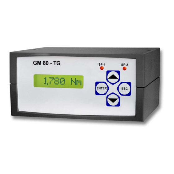
- Page 1 Operating instruction DC Voltage Measuring Amplifier with Data Logger GM 80 TG / PA (V1.__)
- Page 2 Safety Notes General References The enclosed operating instruction is intended for technically qualified personnel who has corresponding knowledge in the field of measurement and industrial process & control technology. The precise information about all safety notes contained in this operation manual and warnings, as well as its perfect technical implementation are precondition for the safe installation, the initiation, the secure operation and the maintenance of technology devices.
- Page 3 Brief Description: The GM 80 TG / PA is a DC measuring amplifier for passive, active sensors or sensors with current interface. GM80 TG Table device with 24 V DC wall power supply GM80 PA Panel device 72 x 144 norm, cut-out in cabinet: 138 x 68 mm Inputs: Passive (SG) 0,35-3,3mV/V;...
- Page 4 By ENTER the new measuring rate will be taken over, by ESC the new measuring rate will be discarded. - Switch off GM 80 TG If the GM80 TG is operating in menu 1 MEASURE it can be switched off, when ESC is pressed for >3 seconds.
- Page 5 GM 80 TG/PA Brief Handling Overview...
- Page 6 Mains Operation: GM80 TG: Wall power supply with 24V DC / 250mA is part of the delivery scope. GM80 PA: The supply voltage of 16-30V DC is connected via a BMS-plug. Battery for Date and Time: A commercial CR2032 lithium battery with 3V is used. If time and date continuously begins at 0.00 hrs and date of 01.01.70, the battery must be exchanged.
- Page 7 Menu Description: 1 MEASURE: Measuring mode SENSOR__: Sensor selection for measuring mode, sensor 0 - 9 Here the sensor parameter set for the measurement is being selected. The sensor parameter set must match the connected sensor. 2 SYSTEM: All system parameters are being stored in this menu column. 2.1 LANG Language adjustment The menu language can be chosen in German, English, French or Spanish.
-
Page 8: Operation
2.8 TIME Date and time adjustment DATE Date TIME Time 2.9 INPUT Mode of operation and limit value adjustments DISPLAY Cont continuous measurement min. measured value is displayed and restored by a trigger pulse. max measured value is displayed and restored by a trigger pulse. LIMIT Limit values are active only when mode of operation is selected. - Page 9 Calibration Procedure: ACT_wCON Active sensor with calibration control 0% LOAD unload sensor 100%Con after pressing ENTER the calibration takes place automatically. SAVE query for takeover of calibration data ACT_nCON Active sensor without calibration control 0% LOAD unload sensor 100%Con calibration by 100 % load (apply the nominal load/nominal torque) or switch to nominal value NOMVALUE enter the nominal value in mV/V or switch to 100 % load...
- Page 10 Operation via the Serial Interface (SCI): Through the serial interface, measurement values can be issued singly or automatically by the GM 80. The commands can be sent to the GM 80 via a terminal program or PLC. If several devices are connected to the RS232-BUS, none of the devices should be operated in the SCI-mode “AUTO”. Protocol set-up 0x02 0xXX...
- Page 11 0xAB: A ... Sensor type, B ... digit of the dec. point (binary coded) Sensor type and digits 1Byte Sensor type: 0xXXXX XXXX |||| 0000 ... active withcalibration control 0%load and 100% load calibration 0001 ... active without calibration control 0%load and 100% load calibration 0010 ...
- Page 12 Read Time: Output: DAY.MONTH.YEAR 2xspace HOURS:MINUTES:SECONDS Write Time: The writing is identically with the data block for receipt of time, however, the data block for writing is protected with a checksum and the corresponding weighted checksum. Read Company Header: With this command the company header, which is stored in the GM 80, can be read. Write Company Header: The input is ended either if 256 characters are received or if the character ETX (0x03) Strg-C is contained in the character string.
- Page 13 Formatting of the Serial Interface Output Output format in SCI mode: HAND: Algebraic sign, measured value, unit, time and CRLF AUTO: 10ms Signed integer and CRLF 100ms Signed integer and CRLF Algebraic sign, measured value, unit, time and CRLF Algebraic sign, measured value, unit, time and CRLF 1min Algebraic sign, measured value, unit, time and CRLF 10min...
- Page 14 Operation and Function Principle of the GM 80-Data Logger The data logger can, if the GM 80 is not in the measuring mode, be read by the menu option 2,7 LOGG - SENDING or by the command "A" via the interface. Outside of the measuring mode the data logger is deleted only by the menu option 2,7 LOGG - DELETION.
- Page 15 Pin Assignment:...
- Page 16 Supplement Device Disposal: Please dispose the unserviceable device according to the legal rules. By this you meet the legal obligations and contribute to the environmental protection! Tendance: The device may be cleaned with a slightly moistened cloth. FAQ – Trouble Shooting Device can not be turned on Battery/accumulator inserted correctly? Connect power supply at operation with accumulators.
Need help?
Do you have a question about the GM 80 TG and is the answer not in the manual?
Questions and answers