Advertisement
WEIGHING INDICATOR
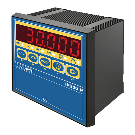
SERIE IPE 50
Short guide
for calibration only
see user manual 1/2 for the different functioning mode, analog output and setpoints
See user manual 2/2 for special functioning mode and output RS232/485, this manual is available on our Web
site www.scaime.com
SUPPORT -> product documentation -> product-user-manuals -> NU-IPE50-2-E-....
(valid from version 07.03)
Advertisement
Table of Contents

Related Manuals for Scaime IPE 50 Series


Summary of Contents for Scaime IPE 50 Series
- Page 1 1/2 for the different functioning mode, analog output and setpoints See user manual 2/2 for special functioning mode and output RS232/485, this manual is available on our Web site www.scaime.com SUPPORT -> product documentation -> product-user-manuals -> NU-IPE50-2-E-….
- Page 2 POWER SUPPLY & START UP Do not connect other equipment to the same socket as the one that the adapter is in. Do not step on or crush the power supply cable Power supply for IPE50 is from 12 to 25Vcc (except IPE50XLI) The display shows in sequence: 07.xx indicate the version of software if you press the key ->0<-...
- Page 3 FONCTIONS Indicates that the weight detected on the weighing system is near zero, ->0<- within the interval of –1/4 to +1/4 of the division. Indicates that the weight is unstable. Indicates that the displayed weight is a net weight. Special mode W1/ SP1 ou W1 or W2 show the functioning with 2 weighing ranges W2 / SP2...
- Page 4 INSTALLATION To obtain the best results it is recommended to install the indicator and the platform (or transducer) in a place with the following conditions: A flat, level surface on which to rest Stable and vibration free Moderate temperature and humidity (15-30°C and 40-70%). No dust or strong vapours No draughts Mains power supply is restricted to 12….
-
Page 5: Block Diagram
BLOCK DIAGRAM Nota : Only for adjustment the menus in bolt are to be configured. Modify the parameter ConFIG -> Param. -> Auto-0 to DiSAb if you want to forbidden the autozero at the start... - Page 6 ADJUSTMENT Nota : The manufacter parameters of the IPE50 unit are : 2mV/V -> 10.000 per 0.001 Attention : the default calibration parameters will probably not match with your application requirements. You have to calibrate the system according to your needs. If the unit is in trade-approved mode, you must open the unit to insert the jumper (see jumper CAL page 11 or To enter the SET-UP environment of the scale, switch on the unit and press the ->T<- key for an instant during the countdown.
- Page 7 1 : 0 ; 1 ; 2 ; 3 ; 4 ; 5 ; 6 ; 7 ; 8 ; 9 (!) 1 9) Select the “rAnGE1” step and press ↵ Set the total capacity of the scale if you exceed this value, the message " ¯ ¯ ¯ ¯ ¯ ¯ " will be displayed on weighing mode. Confirm with the key.
- Page 8 21) DEAd.ld (dead load) If you want to enter the value of the system dead load (empty silo weight for ex) press ↵ in other case press ->0<- (kno.WGt is displayed see paragraph after) You could enter the weight dead load value with the keys If no number after the coma has been selected, you could set value from -99999.9 to 99999.9 If 1number after the coma has been selected, you could set value from -9999.99 to 9999.99 If 2 numbers after the coma has been selected, you could set value from -999.999 to 999.999...
-
Page 9: Error Messages
ERROR MESSAGES While using the indicator, it is possible to incur in the following errors: MESSAGE DESCRIPTION Analog/digital convertor doesn't work. Check the wiring of the loadcells. Measure the signal ADC Err output of the loadcells between the pins + and - sig, the tension must not exceed 15mV. It is displayed if one tries to calibrate a point without first having confirmed the number of PREC. - Page 10 CONNECTION IPE50 PANEL Sensor Sensor 4-wire connection 6 wires connection Sensor connection Relay contacts COM1 COM2 Pour imprimante ou PC Analog output 4/20mA and 0/10 V Depending of the model COM1 or 2 could be bidirectional or COM1 : RS 232 or 485 depending of the 3 unidirectional in function of the setup jumpers position on the PCB...
- Page 11 Version IPE50 Panel with PROFIBUS output (on this version the analog output is not available) loadcell 3 : B-LINE 5 : GND BUS 6 : +5V BUS (active) 8 : A-LINE...
- Page 12 POWER SUPPLY 24 Vdc 1 +24Vdc + 12 to 25Vdc / 3.6 W max 2 GND - 0 Vdc Sensor : attention, the power supply of the sensors (5Vdc) and the maximum power is 120mA for example 8 sensors 350 Ohm connected.
- Page 13 (2) static relays contact ( power : 48Vdc / 100mA ) 48Vdc / 100mA (option 6 relays) contact commun OUT 1 contact relay 1 OUT 2 contact relay 2 OUT 6 contact relay 6 (2) opto-insulated inputs You must connect the input to the com with a contact and a power supply (12 to 24 VCC).
- Page 14 IPE50 DIN and XLI Sensor 1 / 6 wire connection Sensors 1 …..4 1 sensor must be connected on this channel 4 wire connection only Channel 4 Channel 1 You must connect at least 1 sensor Jumper openned : trade approved 4/20mA 0/10V IPE50 DIN and XLI...
- Page 15 POWER supply 24 Vcc (110/220Vac for IPE50 XLI on the power supply cable) 1 +24Vdc + 12 to 25Vdc / 3.6 W max 2 GND - 0 Vdc Sensor : attention, the power supply of the sensors (5Vdc) is the same for the 4 channels and the maximum power is 120mA (for all the channels) for example 8 sensors 350 Ohm connected on a same channel or on 4 channels.
- Page 16 RS 485 SERIAL PORT On the same RS485 network, it is possible to connect up to 32 units On the RS485 network normally one connects 2 termination resistors of 120 Ohm (shown with "R" in figure). Only on the 2 devices which are at the end of the network. Use an appropriate cable for RS485 connections, the twisted 2x24 AWG duplex cable, shielded with an external sheathing + aluminium band.
Need help?
Do you have a question about the IPE 50 Series and is the answer not in the manual?
Questions and answers