Table of Contents
Advertisement
Quick Links
Advertisement
Table of Contents

Related Manuals for Scaime IPM25


Summary of Contents for Scaime IPM25
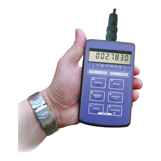
- Page 1 TEDS IPM25 Strain Gauge or Load Cell Hand Held Display User Manual www.scaime.com...
-
Page 2: Table Of Contents
Calibration Menu.............................. 12 Millivolt per Volt Calibration Menu ........................14 Operation Features ............................15 Normal Display Operation ..........................15 Switching the IPM25 On/Off ..........................15 RANGE Button ..............................15 HOLD Button ..............................16 GROSS/NET Button ............................16 SHUNT CAL Button ............................16 PEAK Button .............................. -
Page 3: What Is Teds
- Reduced configuration time by eliminating manual data entry - Better sensor tracking by storing data sheets electronically - Improved accuracy by providing detailed calibration information - Simplified asset management by eliminating paper data sheets - Reliable sensor location by identifying individual sensors electronically IPM25 User Manual... -
Page 4: Introduction
50mV/V. Bridge resistances from 85 upwards can be used with the IPM25. Configuration and calibration of the IPM25 is achieved using the front panel push buttons to navigate through a very simple menu structure. -
Page 5: Electrical Connection Information
Sensor Connections J9 TEDs Position RS232 option There are six push buttons on the front panel of the IPM25, which are available for use in normal operation. Each of these is described below:- See next page for Charge & TEDs position... - Page 6 Front Panel Button Function of Button in Normal Operation Mode To switch the IPM25 ON or OFF press and hold the button The RANGE button allows the user to toggle between two independent scales. An LED highlights the range that has been selected.
-
Page 7: Menu Structure
Menu Structure The IPM25 has two menus, details of which are outlined below:- A CONFIGURATION MENU, which enables the user to tailor the operation to meet a specific application requirement. The values selected in the CONFIGURATION MENU are completely independent for each range. - Page 8 0000000 donE tAbLE? InPut LO 0000000 dISP LO InPut HI 0000000 dISP HI 0000000 SEt OFFS 0000000 donE CAL VAL? SEt 9Ain 0000000 tedS EnAbLEd? RETURN TO NORMAL DISPLAY MODE * Note:Only when TEDS is disabled IPM25 User Manual...
-
Page 9: Millivolt Per Volt Calibration Menu Structure
Millivolt per Volt Calibration Menu Structure To access the millivolt CALIBRATION MENU, Press and hold for 10 seconds 1.00000 5.0 gAIn 5.0 OFFS 1.00000 50.0 gAIn 1.00000 50.0 OFFS 0.00000 CuSt RETURN TO NORMAL DISPLAY MODE IPM25 User Manual... -
Page 10: Configuration Menu
To skip to next menu item Press To set overload alarm This allows the setting of a visual overload. The value entered is the display value at which the IPM25 displays OUErLOAd. OUEr Values between can be entered, using the... - Page 11 AUtO to conserve battery life. Values between can be entered leaves the IPM25 permanently powered), using arrows to select a digit and the arrows to increment or decrement the digits. Press to accept the value and move onto the next parameter.
-
Page 12: Calibration Menu
To select 50mV/V you need to power down the unit and access the internal circuit board. Move link LK1 and place it onto JP1. Power on the IPM25 and return to this point of the calibration menu. You will notice that the menu parameter has changed to 50.0, press... - Page 13 If you have chosen to enter the TEDS you will be prompted whether you want to select if you do not press otherwise press . If you have selected enabled, two EnAbLEd? flashing indicators will appear. For more detailed TEDS calibration information, please refer to the TEDS section of the manual. IPM25 User Manual...
-
Page 14: Millivolt Per Volt Calibration Menu
5mV/V offset. 50 OFFS Here the factory offset value can be changed to a measured value (see Milli-Volt Calibration Procedure – back end of manual). Once the derived value has been entered Press to confirm. IPM25 User Manual... -
Page 15: Operation Features
Normal Display Operation The IPM25 has a full 7 digit display, which can be scaled using the calibration menu to suit the application it is to be used in. The display can display the instantaneous, peak or trough values. It is also possible to hold the display value (this only operates when not in peak or trough mode). -
Page 16: Hold Button
PEAK Button When pressed this button puts the IPM25 into peak mode. This will display the highest display reading and hold it on the display until it is reset or a higher value is reached. To reset the peak display, press the peak and trough buttons simultaneously. -
Page 17: Configuration Menu Parameters
The benefit is that the battery life, based on a 350Ω sensor bridge being connected, increases from 45 hours to 450 hours. It is also important to remember that when the IPM25 is re-calibrated with a sensor, the power save facility will be automatically turned off. The power save facility will therefore need to be re-activated after calibration has been completed. -
Page 18: Calibration Menu Parameters
If however, a higher sensitivity sensor is used with the IPM25, it will be necessary to gain access to the internal PCB (you must turn the IPM25 off) to move link LK1 to JP1 (see picture below) to allow the IPM25 to accept sensitivities of up to 50mV/V. -
Page 19: Calibration Procedures
TEDS peripheral has been made. When there is a loss of connection these LEDs flash. When changing a sensor the IPM25 should be power cycled as this is when the TEDS data is read. Calibration Procedures are not available when TEDS is enabled. - Page 20 When the value has been set press You should now see displayed. This means the calibration was successful, press to the IPM25 to normal donE operation mode, with the new calibration data stored. If you see FaiLEd, then you will need to repeat the calibration, checking that you have completed the procedure in the correct order, and that the sensor is connected correctly.
-
Page 21: Millivolt Per Volt Calibration Procedure
1. Ensure that the factory settings for gain and offset are set to 1 and 0, respectively. See millivolt per volt calibration section to do this. 2. Begin by connecting up the model IPM25 and a high precision Multimeter to the calibration source set at 2.5mV/V with a 350Ω load. -
Page 22: Specifications
LEDs: Low Battery warning; peak; trough; hold; net; shunt cal; range Tactile Keys with recessed rims for:- ON/OFF Switches IPM25 power on/off RANGE Selects between two ranges HOLD Hold the current display value, press again to release Control Variables Front Panel User Keys: GROSS/NET Zero’s display (±100% range)
Need help?
Do you have a question about the IPM25 and is the answer not in the manual?
Questions and answers