
Related Manuals for Endress+Hauser Proline Prowirl 72


Summary of Contents for Endress+Hauser Proline Prowirl 72
-
Page 1: Operating Instructions
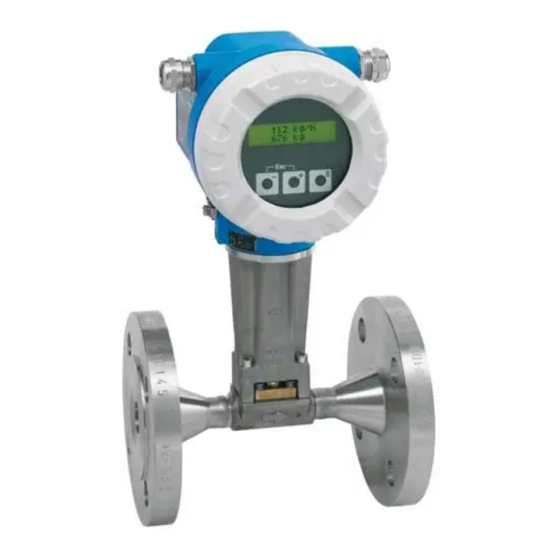
Operating Instructions Proline Prowirl 72 Vortex Flow Measuring System BA00095D/06/EN/13.11 71154520 Valid as of version: V 1.00.XX (Device software) - Page 2 Proline Prowirl 72 FOUNDATION Fieldbus Endress + Hauser...
-
Page 3: Table Of Contents
Proline Prowirl 72 FOUNDATION Fieldbus Contents Contents Contents ......3 4.3.3 Terminal assignment ....28 4. - Page 4 Contents Proline Prowirl 72 FOUNDATION Fieldbus 10.1.10Frequency ranges for air and water ..71 Index ......123 10.1.11Mechanical construction .
-
Page 5: Safety Instructions
• The device must be operated by persons authorized and trained by the facility's owner-operator. Strict compliance with the instructions in these Operating Instructions is mandatory. • Endress+Hauser is willing to assist in clarifying the chemical resistance properties of parts wetted by special fluids, including fluids used for cleaning. However, small changes in temperature, concentration or the degree of contamination in the process can result in changes of the chemical resistance properties. -
Page 6: Return
• Always enclose a fully completed "Declaration of Contamination" form with the device. Only then can Endress+Hauser transport, examine and repair a returned device. • Enclose special handling instructions if necessary, for example a safety data sheet as per European Directive 1907/2006/EG. -
Page 7: Identification
2 Identification Identification 2. 1 Device designation The "Proline Prowirl 72 FOUNDATION Fieldbus" flowmeter system consists of the following components: • Transmitter Proline Prowirl 72 FOUNDATION Fieldbus • Prowirl F or Prowirl W sensor In the compact version, the transmitter and sensor form a mechanical unit; in the remote version they are mounted separate from one another. -
Page 8: Sensor Nameplate, Remote Version
2 Identification Proline Prowirl 72 FOUNDATION Fieldbus 2.1.2 Sensor nameplate, remote version PROWIRL W IP67/NEMA/Type 4X 72WXX-XXXXXXXXXXXX Order Code: 12345678901 2007 Ser.No.: ABCDEFGHJKLMNPQRST TAG No.: pnom = PS = 10bar / ptest = 20bar Size: DN50 K-factor: 1.0000 P/L Meter Body: CF3M/F316/F316L/1.4404, 316L... -
Page 9: Certificates And Approvals
Regulation and Laboratory Procedures" and the EMC requirements as per IEC/EN 61326. The measuring system described in these Operating Instructions therefore complies with the legal requirements of the EU Directives. Endress+Hauser confirms this by affixing the CE mark to it and by issuing the CE declaration of conformity. -
Page 10: Installation
3 Installation Proline Prowirl 72 FOUNDATION Fieldbus Installation Incoming acceptance, transport, storage 3.1.1 Incoming acceptance On receipt of the goods, check the following points: • Check the packaging and the contents for damage. • Check the shipment, make sure nothing is missing and that the scope of supply matches your order. -
Page 11: Installation Conditions
Proline Prowirl 72 FOUNDATION Fieldbus 3 Installation Installation conditions Note the following points: • The measuring device requires a fully developed flow profile as a prerequisite for correct volume flow measurement. The inlet and outlet runs must be taken into account (see Page 14). -
Page 12: Orientation
3 Installation Proline Prowirl 72 FOUNDATION Fieldbus 3.2.3 Orientation The device can be installed basically in any orientation. Please consider the following, however (Fig. 6): • In the case of liquids, there should be upward flow in vertical pipes to avoid partial pipe filling (see orientation A). -
Page 13: Heat Insulation
Proline Prowirl 72 FOUNDATION Fieldbus 3 Installation 3.2.4 Heat insulation Some fluids require suitable measures to avoid heat transfer at the sensor. A wide range of materials can be used to provide the required insulation. When insulating, please ensure that a sufficiently large area of the housing support is exposed. The uncovered part serves as a radiator and protects the electronics from overheating (or undercooling). -
Page 14: Inlet And Outlet Run
3 Installation Proline Prowirl 72 FOUNDATION Fieldbus 3.2.5 Inlet and outlet run As a minimum, the inlet and outlet runs shown below must be observed to achieve the specified accuracy of the device. The longest inlet run shown must be observed if two or more flow disturbances are present. -
Page 15: Vibrations
3 Installation Perforated plate flow conditioner A specially designed perforated plate flow conditioner, available from Endress+Hauser, can be installed if it is not possible to observe the inlet runs required. The flow conditioner is fitted between two piping flanges and centered with mounting bolts. Generally, this reduces the inlet run required to 10 ... -
Page 16: Installation
Seals projecting into the flow current have a negative effect on the vortex formation after the bluff body and cause inaccurate measurement. The gaskets provided by Endress+Hauser for the wafer version have therefore an inner diameter with a bigger inner diameter than the piping. -
Page 17: Rotating The Transmitter Housing
Proline Prowirl 72 FOUNDATION Fieldbus 3 Installation 3.3.2 Rotating the transmitter housing The electronics housing can be rotated continuously 360° on the housing support. Loosen the safety screw. Turn the transmitter housing to the desired position (max. 180° in each direction to the stop). -
Page 18: Mounting Transmitter (Remote)
3 Installation Proline Prowirl 72 FOUNDATION Fieldbus 3.3.4 Mounting transmitter (remote) The transmitter can be mounted in the following ways: • Wall mounting • Pipe mounting (with separate mounting kit, accessories Page 44) The transmitter and the sensor must be mounted separate in the following circumstances: •... -
Page 19: Post-Installation Check
Proline Prowirl 72 FOUNDATION Fieldbus 3 Installation Post-installation check Perform the following checks after installing the measuring device in the piping: Device condition and specifications Notes Is the device damaged (visual inspection)? Do the process temperature/pressure, ambient temperature, measuring range see Page 62 ff. -
Page 20: Wiring
Wiring Warning! When connecting Ex-certified devices, please refer to the notes and diagrams in the Ex-specific supplement to these Operating Instructions. Please do not hesitate to contact your Endress+Hauser representative if you have any questions. 4. 1 FOUNDATION Fieldbus cable specifications 4.1.1... -
Page 21: Maximum Overall Cable Length
Proline Prowirl 72 FOUNDATION Fieldbus 4 Wiring 4.1.2 Maximum overall cable length The maximum network expansion depends on the type of protection and the cable specifications. The overall cable length combines the length of the main cable and the length of all spurs (>1 m/3.28 ft ). -
Page 22: Connecting The Remote Version
4 Wiring Proline Prowirl 72 FOUNDATION Fieldbus 4. 2 Connecting the remote version 4.2.1 Connecting the sensor Note! • The remote version must be grounded. In doing so, the sensor and transmitter must be connected to the same potential matching. -
Page 23: Cable Specifications, Connecting Cable
Proline Prowirl 72 FOUNDATION Fieldbus 4 Wiring 4.2.2 Cable specifications, connecting cable The specifications of the cable connecting the transmitter and the sensor of the remote version are as follows: • 4 2 0.5 mm² (AWG 20) PVC cable with common shield (4 pairs, pair-stranded) -
Page 24: Connecting The Transmitter
4 Wiring Proline Prowirl 72 FOUNDATION Fieldbus 4. 3 Connecting the measuring unit Field instruments can be connected to the FOUNDATION Fieldbus in two ways: • Connection via conventional cable gland Kap. 4.2.1 • Connection via prefabricated fieldbus connector (option) Kap. 4.3.2 4.3.1... - Page 25 Proline Prowirl 72 FOUNDATION Fieldbus 4 Wiring Procedure for connecting the transmitter, Non-Ex, Ex i/IS and Ex n version (Fig. 16) Unscrew the cover (a) of the electronics compartment from the transmitter housing. Remove the display module (b) from the retaining rails (c) and refit onto right retaining rail with the left side (this secures the display module).
- Page 26 4 Wiring Proline Prowirl 72 FOUNDATION Fieldbus Procedure for connecting the transmitter, Ex d/XP version (Fig. 17) Release the securing clamp (a) of the connection compartment cover. Screw the connection compartment cover (b) off the transmitter housing. Push the power supply/fieldbus cable through the cable gland (c).
-
Page 27: Fieldbus Connector
4-channel or 8-channel distribution modules. The device can therefore be supplied with the option of a ready-mounted fieldbus connector. Fieldbus connectors for retrofitting can be ordered from Endress+Hauser as a spare part (Page 56). Supply line/T-box shielding Use cable glands with good EMC properties, if possible with all-round contact of the cable shielding (Iris spring). -
Page 28: Terminal Assignment
4 Wiring Proline Prowirl 72 FOUNDATION Fieldbus 4.3.3 Terminal assignment Terminal no. (inputs/outputs) Order variant 72***-***********K FF + FF – 4. 4 Degree of protection The measuring device meets all the requirements for IP 67 (NEMA 4X). Compliance with the following points is mandatory following installation in the field or servicing in order to ensure that IP 67 (NEMA 4X) protection is maintained: •... -
Page 29: Post-Connection Check
Proline Prowirl 72 FOUNDATION Fieldbus 4 Wiring 4. 5 Post-connection check Perform the following checks after completing electrical installation of the measuring device: Device condition and specifications Notes Are cables or the device damaged (visual inspection)? Electrical connection Notes... -
Page 30: Operation
5 Operation Proline Prowirl 72 FOUNDATION Fieldbus Operation 5. 1 Quick operation guide You have a number of options for configuring and commissioning the device: 1. Operating programsPage 33 The configuration of FOUNDATION Fieldbus functions and device-specific parameters is primarily done via the fieldbus interface. -
Page 31: Display Elements
Proline Prowirl 72 FOUNDATION Fieldbus 5 Operation 5. 2 Display elements 5.2.1 Display Local display The local display enables you to read important parameters directly at the measuring point. The display consists of two lines; this is where measured values and/or status variables (e.g. bar graph) are displayed. -
Page 32: Error Message Display
5 Operation Proline Prowirl 72 FOUNDATION Fieldbus 5.2.3 Error message display Type of error Errors which occur during commissioning or measuring operation are displayed immediately. If two or more system or process errors occur, only the error with the highest priority is the one shown on the display. -
Page 33: Operating Programs
• Network configuration CFF file (Common File Format: *.cff) These files can be acquired as follows: • Free of charge via the internet www.endress.com • From Endress+Hauser by quoting the order number (No. 50097199) • From the Fieldbus Foundation Organization www.fieldbus.org Note! Make sure you are using the correct system files for integrating field devices into the host system. -
Page 34: Current Device Description Files
5 Operation Proline Prowirl 72 FOUNDATION Fieldbus 5.4.3 Current device description files The following table illustrates the suitable device description file for the operating tool in question and then indicates where these can be obtained. Access via FOUNDATION Fieldbus: Valid for I/O software 1.00.XX... -
Page 35: Hardware Settings
Proline Prowirl 72 FOUNDATION Fieldbus 5 Operation 5. 5 Hardware settings 5.5.1 Switching the write protection and simulation mode on and off Hardware write protection and simulation mode (for AI and DO function block) can be switched on and off by means of DIP switches on the I/O board or the amplifier board. When write protection is active, parameters cannot be modified. -
Page 36: Commissioning
6 Commissioning Proline Prowirl 72 FOUNDATION Fieldbus Commissioning 6. 1 Function check Make sure that all final checks have been completed before you commission your measuring point: • "Post-installation check" checklist Page 19 • "Post-connection check" checklist Page 29 Note! •... -
Page 37: Commissioning Via Foundation Fieldbus
Proline Prowirl 72 FOUNDATION Fieldbus 6 Commissioning 6. 2 Commissioning via FOUNDATION Fieldbus Note the following points: • The files required for commissioning and network configuration can be obtained as described on Page 33. • In the case of the FOUNDATION Fieldbus, the device is identified in the host or configuration system by means of the device ID (DEVICE_ID). - Page 38 6 Commissioning Proline Prowirl 72 FOUNDATION Fieldbus Using the DEVICE_ID noted, identify the field device and assign the desired tag name (PD_TAG) to the fieldbus device in question. Factory setting: E+H_PROWIRL_72_xxxxxxxxxxx A0003789 Fig. 25: Screen display in the configuration program "NI-FBUS Configurator" (National Instruments) after the connection has been established Configuring the "Resource Block"...
- Page 39 Proline Prowirl 72 FOUNDATION Fieldbus 6 Commissioning 10. Enter the desired name for the block (optional). Factory setting: TRANSDUCER_FLOW_ xxxxxxxxxxx 11. Open the Transducer Block "Flow". 12. Now configure the device-specific parameters relevant for your application. – Enabling code in "Un-/Locking - Access Code" parameter Transducer Block "Flow"...
- Page 40 6 Commissioning Proline Prowirl 72 FOUNDATION Fieldbus Note! – Please note that device parameter modifications are only possible once a valid enabling code has been entered in the "Un-/Locking - Access Code" parameter. – The selection of system units in the Transducer Blocks does not have any effect on the desired units, which are to be transmitted via the FOUNDATION Fieldbus interface.
- Page 41 Proline Prowirl 72 FOUNDATION Fieldbus 6 Commissioning 18. In the L_TYPE parameter, select the type of linearization for the input variable (direct, indirect, indirect sq. root)Page 80 ff. " Caution! Please note that if the "Direct" linearization type is selected, the settings in the OUT_SCALE parameter group are not taken into account.
- Page 42 6 Commissioning Proline Prowirl 72 FOUNDATION Fieldbus System configuration / connection of function blocks (Fig. 26): 22. A final "overall system configuration" is necessary so that the operating mode of the Analog Input Function Block can be set to AUTO and the field device is integrated into the system application....
-
Page 43: Maintenance
• The time span between the individual replacements depends on the fluid properties. • Replacement seals (accessory)Page 44. Only Endress+Hauser sensor seals may be used. Replacing housing seals The housing seals must be clean and undamaged when inserted into their grooves. -
Page 44: Accessories
8 Accessories Proline Prowirl 72 FOUNDATION Fieldbus Accessories Various accessories, which can be ordered separately from Endress+Hauser, are available for the transmitter and the sensor. Your Endress+Hauser service organization can provide detailed information on the order codes in question. Accessory... - Page 45 Proline Prowirl 72 FOUNDATION Fieldbus 8 Accessories Accessory Description Order code PMC71 ********* Pressure Cerabar S is used for measuring the absolute and gauge pressure of PMP71 ********* transmitter gases, steams and liquids. Cerabar S TMT 165...
-
Page 46: Troubleshooting
9 Troubleshooting Proline Prowirl 72 FOUNDATION Fieldbus Troubleshooting 9. 1 Troubleshooting instructions Always start troubleshooting with the checklists below if faults occur after startup or during operation. This takes you directly (via various queries) to the cause of the problem and the appropriate remedial measures. - Page 47 Proline Prowirl 72 FOUNDATION Fieldbus 9 Troubleshooting Faulty connection to fieldbus host system (contd.) Fieldbus voltage Check that a min. bus voltage of 9 V DC is present at terminals 1/2. Permissible range: 9 to 32 V DC Network structure Check permissible fieldbus length and number of spursPage 21...
- Page 48 9 Troubleshooting Proline Prowirl 72 FOUNDATION Fieldbus – Parameters cannot be changed 1. Parameters that only show values or settings cannot be changed! 2. The hardware write protection is enabled. Disable the write protection Page 35 – No write access to parameters Note!...
-
Page 49: System And Process Error Messages
Proline Prowirl 72 FOUNDATION Fieldbus 9 Troubleshooting 9. 2 System and process error messages General notes The measuring device always assigns system and process errors which occur to two types of error messages, resulting in different weightings. "Fault message" error message type: •... - Page 50 9 Troubleshooting Proline Prowirl 72 FOUNDATION Fieldbus Analog Input Error messages: Error messages in the Cause of error / remedy Output Transducer Block – FOUNDATION Fieldbus (FF) * funct. block variables – Local display "Diagnosis" error messages affected...
- Page 51 Proline Prowirl 72 FOUNDATION Fieldbus 9 Troubleshooting Analog Input Error messages: Error messages in the Cause of error / remedy Output Transducer Block – FOUNDATION Fieldbus (FF) * funct. block variables – Local display "Diagnosis" error messages affected Device status message (FF): OUT.
- Page 52 9 Troubleshooting Proline Prowirl 72 FOUNDATION Fieldbus Analog Input Error messages: Error messages in the Cause of error / remedy Output Transducer Block – FOUNDATION Fieldbus (FF) * funct. block variables – Local display "Diagnosis" error messages affected...
- Page 53 Proline Prowirl 72 FOUNDATION Fieldbus 9 Troubleshooting Analog Input Error messages: Error messages in the Cause of error / remedy Output Transducer Block – FOUNDATION Fieldbus (FF) * funct. block variables – Local display "Diagnosis" error messages affected Device status message (FF): OUT.
-
Page 54: Process Errors Without Messages
• Support the piping near the device. If these measures do not solve the problem, your Endress+Hauser service organization can adjust the filters of the device to suit your special application.... - Page 55 The following options are available for tackling problems of this nature: some other fault not described above has occurred. Request the services of an Endress+Hauser service technician In these instances, please contact If you contact our service organization to have a service technician sent out, please...
-
Page 56: Spare Parts
Note! You can order spare parts directly from your Endress+Hauser service organization by quoting the serial number printed on the transmitter nameplate (Page 7). Spare parts are shipped as sets comprising the following parts: •... -
Page 57: Installing And Removing Electronics Boards
Proline Prowirl 72 FOUNDATION Fieldbus 9 Troubleshooting 9. 5 Installing and removing electronics boards 9.5.1 Non-Ex, Ex i/IS and Ex n version Note! • When connecting Ex-certified devices, please refer to the notes and diagrams in the Ex-specific supplement to these Operating Instructions. - Page 58 9 Troubleshooting Proline Prowirl 72 FOUNDATION Fieldbus A0003792 Fig. 28: Installing and removing electronics boards Non-Ex, Ex-i and Ex n version Cover of electronics compartment Display module Display module retaining rails Fixing screw for cover of connection compartment Connection compartment cover...
-
Page 59: Ex D/Xp Version
Proline Prowirl 72 FOUNDATION Fieldbus 9 Troubleshooting 9.5.2 Ex d/XP version Note! • When connecting Ex-certified devices, please refer to the notes and diagrams in the Ex-specific supplement to these Operating Instructions. • Risk of damaging electronic components (ESD protection). - Page 60 9 Troubleshooting Proline Prowirl 72 FOUNDATION Fieldbus A00003793 Fig. 29: Installing and removing electronics boards Ex d/XP version Clamp for cover of connection compartment Cover of connection compartment Terminal connector Fixing screws for I/O board (COM module) I/O board (COM module)
-
Page 61: Software History
Proline Prowirl 72 FOUNDATION Fieldbus 9 Troubleshooting 9. 6 Software history Date Software version Software modifications Documentation 06.2004 Communication module: Original software 71041313/01.07 V 1.00.00 50107507/06.04 03.2004 Amplifier: Supplement: V 1.01.03 • Support of the Prowirl 72, 73 FOUNDATION Fieldbus communication module. -
Page 62: Technical Data
10 Technical data Proline Prowirl 72 FOUNDATION Fieldbus Technical data 10. 1 Technical data at a glance 10.1.1 Application The measuring system is used to measure the volume flow of saturated steam, superheated steam, gases and liquids. If the process pressure and process temperature are constant, the measuring device can also output the flow as the calculated mass flow and corrected volume flow. -
Page 63: Foundation Fieldbus Output
– Nominal diameters larger than DN 100 (4") Note! By using the selection and planning program "Applicator", you can determine the exact values for the fluid you use. You can obtain the Applicator from your Endress+Hauser sales center or on the Internet under www.endress.com. K-factor range The table is used for orientation purposes. - Page 64 10 Technical data Proline Prowirl 72 FOUNDATION Fieldbus Error current 0 mA Permissible fieldbus feed 9 to 32 V voltage Data transmission rate 31.25 kBit/s, voltage mode Signal coding Manchester II Bus times Min. rest between two telegrams: MIN_INTER_PDU_DELAY = 6 octet time (transmission time per octet)
- Page 65 Proline Prowirl 72 FOUNDATION Fieldbus 10 Technical data Block information, execution times Block Base index Execution time [ms] Resource Block – Transducer Block "Flow" – Transducer Block "Totalizer" – Transducer Block "Display" – Transducer Block "Diagnosis" – Transducer Block "Service"...
-
Page 66: Power Supply
10 Technical data Proline Prowirl 72 FOUNDATION Fieldbus 10.1.5 Power supply Electrical connection see Page 20 ff. Supply voltage 9 to 32 V DC Cable entry Power supply cable/fieldbus cable (outputs): • Cable entry: M20 1.5 (6 to 12 mm / 0.24 to 0.47 inch) •... -
Page 67: Operating Conditions: Installation
Proline Prowirl 72 FOUNDATION Fieldbus 10 Technical data Wafer: DN 15 (½"): ±15% of the internal diameter DN 25 (1"): ±12% of the internal diameter DN 40 (1½"): ±9% of the internal diameter DN 50 ( 2"): ±8% of the internal diameter Repeatability ±0.25% o.r. -
Page 68: Operating Conditions: Process
10 Technical data Proline Prowirl 72 FOUNDATION Fieldbus Acceleration up to 1 g ((with factory setting for amplification), Vibration resistance 10 to 500 Hz, following IEC 60068-2-6 Electromagnetic compatibility To IEC/EN 61326 and NAMUR Recommendation NE 21. (EMC) 10.1.9... - Page 69 Proline Prowirl 72 FOUNDATION Fieldbus 10 Technical data Medium pressure Pressure-temperature curve to EN (DIN), (stainless steel) PN 10 to 40 Prowirl 72W and 72F PN 63 to 250 Prowirl 72F [psi] [bar] 4000 [psi] [bar] [bar] PN 250...
- Page 70 10 Technical data Proline Prowirl 72 FOUNDATION Fieldbus Pressure-temperature curve according to JIS B2220, stainless steel 10 to 20K Prowirl 72W and 72F 40K Prowirl 72F [psi] [bar] [bar] 40 K 20 K 10 K -200 -100 -200 -100 [°C]...
-
Page 71: 10Frequency Ranges For Air And Water
Proline Prowirl 72 FOUNDATION Fieldbus 10 Technical data 10.1.10 Frequency ranges for air and water For further media, e.g. steam, you can find information in the Applicator. Prowirl 72W (SI units) DN (DIN) Air (at 0 °C, 1.013 bar) Water (at 20 °C) K-factor Corrected volume flow (e) in [m³/h]... - Page 72 10 Technical data Proline Prowirl 72 FOUNDATION Fieldbus Prowirl 72F (SI units) DN (DIN) Air (at 0 °C, 1.013 bar) Water (at 20 °C) K-factor Corrected volume flow (e) in [m³/h] Volume flow (e) in [m³/h] [Pulse/dm³] Frequency range Frequency range min to max.
-
Page 73: 11Mechanical Construction
Proline Prowirl 72 FOUNDATION Fieldbus 10 Technical data 10.1.11 Mechanical construction Design, dimensions See Technical Information TI070D/06/en Weight See Technical Information TI070D/06/en Material Transmitter housing: • Powder-coated die-cast aluminum AlSi10Mg – In accordance with EN 1706/EN AC-43400 (EEx d/XP version: cast aluminum... -
Page 74: 12Human Interface
The measuring device is in conformity with the statutory requirements of the EC Directives. CE approval Endress+Hauser confirms successful testing of the device by affixing to it the CE mark. C-Tick mark The measuring device meets the EMC requirements of the "Australian Communications and Media Authority (ACMA)". - Page 75 PED is required, this must be ordered explicitly. For devices with nominal diameters less than or equal to DN 25 (1"), this is neither possible nor necessary. • With the identification PED/G1/III on the sensor nameplate, Endress+Hauser confirms conformity with the "Basic safety requirements" of Appendix I of the Pressure Equipment Directive 97/23/EC.
-
Page 76: 14Ordering Information
10.1.15 Accessories Various accessories, which can be ordered separately from Endress+Hauser, are available for the transmitter and the sensor (Page 44). Your Endress+Hauser service organization can provide detailed information on the order codes of your choice. -
Page 77: 10. 2 Dimensions Of Flow Conditioner
Proline Prowirl 72 FOUNDATION Fieldbus 10 Technical data 10. 2 Dimensions of flow conditioner Dimensions according to: • EN 1092-1 (DIN 2501) • ANSI B16.5 • JIS B2220 Material 1.4435 (316L), in conformity with NACE MR0175-2003 and MR0103-2003 A0001941 D1: The flow conditioner is fitted at the outer diameter between the bolts.... - Page 78 10 Technical data Proline Prowirl 72 FOUNDATION Fieldbus Dimensions of flow conditioner according to ANSI Pressure Centering diameter D1 / D2 * Weight rating mm (inch) mm (inch) kg (lbs) Cl. 150 50.1 (1.97) 0.03 (0.07) ½" 2.0 (0.08) Cl. 300 56.5 (2.22)
- Page 79 Proline Prowirl 72 FOUNDATION Fieldbus 10 Technical data Dimensions of flow conditioner according to JIS Pressure Centering diameter [mm] D1 / D2 * Weight rating [mm] [kg] 60.3 0.06 60.3 0.06 66.3 0.06 76.3 0.14 76.3 0.14 81.3 0.14 91.3 0.31...
-
Page 80: Operation Via Foundation Fieldbus
In addition to these blocks, a field device may have other blocks, e.g. several Analog Input Function Blocks if more than one process variable is available from the field device. Proline Prowirl 72 FOUNDATION Fieldbus has the following blocks: • A Resource Block (device block) •... -
Page 81: Resource Block (Device Block)
Proline Prowirl 72 FOUNDATION Fieldbus 11 Operation via FOUNDATION Fieldbus The sensor signal is first prepared in the measuring block, the Transducer Block "Flow". The process variables mass flow and volume flow are then passed to the Analog Input Function Blocks for technical processing (e.g. -
Page 82: Block Status
11 Operation via FOUNDATION Fieldbus Proline Prowirl 72 FOUNDATION Fieldbus 11.2.2 Block status The current operating status of the Resource Block is displayed in the RS_STATE parameter. The Resource Block can assume the following states: – STANDBY The Resource Block is in the OOS operating mode. The other blocks cannot be executed. -
Page 83: Resource Block Parameters
• The ALARM_SUM parameter shows the current status of all the process alarms. 11.2.5 Resource Block parameters The following table shows all the Endress+Hauser-specific parameters of the Resource Block. Resource Block (device block) / base index 400 Parameter Write access for... -
Page 84: 11. 3 Transducer Block
Proline Prowirl 72 FOUNDATION Fieldbus 11. 3 Transducer Block The Transducer Block of the Proline Prowirl 72 FOUNDATION Fieldbus contains all the measuring and device-specific parameters of the flowmeter. All the settings directly connected with the application/flow measurement are made here.... -
Page 85: Block Output Variables
" Caution! Changing the settings of the service functions can result in a malfunction or device failure. Should this occur, remove the device and return it to Endress+Hauser. 11.3.1 Block output variables The Transducer Blocks make the following output variables (process variables) available: •... -
Page 86: Selecting The Operating Mode
11 Operation via FOUNDATION Fieldbus Proline Prowirl 72 FOUNDATION Fieldbus 11.3.2 Selecting the operating mode The operating mode is set by means of the MODE_BLK parameter group (see Page 87). The Transducer Blocks support the following operating modes: • AUTO (automatic mode) •... -
Page 87: 11. 4 Foundation Fieldbus Parameters
11 Operation via FOUNDATION Fieldbus 11. 4 FOUNDATION Fieldbus parameters The following table lists all the specified FOUNDATION Fieldbus parameters of the Transducer Blocks. The Endress+Hauser-specific parameters are described as of Page 89. FOUNDATION Fieldbus parameters (Transducer Blocks) Parameter Write access for... - Page 88 11 Operation via FOUNDATION Fieldbus Proline Prowirl 72 FOUNDATION Fieldbus FOUNDATION Fieldbus parameters (Transducer Blocks) Parameter Write access for Description operating mode (MODE_BLK) BLOCK_ERR Read only The active block errors appear on the display. Display: • OUT OF SERVICE The block is in the "out of service" operating mode.
-
Page 89: Endress+Hauser Parameters
11 Operation via FOUNDATION Fieldbus 11. 5 Endress+Hauser parameters: Transducer Block "Flow" The following table shows all the Endress+Hauser-specific parameters of the Transducer Block "Flow". These can only be changed after entering an enabling code in the "Un-/Locking - Access Code"... - Page 90 11 Operation via FOUNDATION Fieldbus Proline Prowirl 72 FOUNDATION Fieldbus Transducer Block "Flow" (Endress+Hauser parameters) / base index 500 Parameter Write access for Description operating mode (MODE_BLK) System Unit - AUTO - OOS Use this function to select the unit for the volume flow (volume/time).
- Page 91 Proline Prowirl 72 FOUNDATION Fieldbus 11 Operation via FOUNDATION Fieldbus Transducer Block "Flow" (Endress+Hauser parameters) / base index 500 Parameter Write access for Description operating mode (MODE_BLK) System Unit - AUTO - OOS Use this function to select the unit for the calculated mass flow.
- Page 92 11 Operation via FOUNDATION Fieldbus Proline Prowirl 72 FOUNDATION Fieldbus Transducer Block "Flow" (Endress+Hauser parameters) / base index 500 Parameter Write access for Description operating mode (MODE_BLK) System Unit - AUTO - OOS Use this function to select the unit for the corrected volume flow.
- Page 93 Proline Prowirl 72 FOUNDATION Fieldbus 11 Operation via FOUNDATION Fieldbus Transducer Block "Flow" (Endress+Hauser parameters) / base index 500 Parameter Write access for Description operating mode (MODE_BLK) System Unit - AUTO - OOS Use this function to select the desired unit for the operating temperature Temperature to be entered in the "Process Param.
- Page 94 11 Operation via FOUNDATION Fieldbus Proline Prowirl 72 FOUNDATION Fieldbus Transducer Block "Flow" (Endress+Hauser parameters) / base index 500 Parameter Write access for Description operating mode (MODE_BLK) Process Param. - AUTO - OOS Use this function to enter a fixed value for the density at process Operating ...
- Page 95 Proline Prowirl 72 FOUNDATION Fieldbus 11 Operation via FOUNDATION Fieldbus Transducer Block "Flow" (Endress+Hauser parameters) / base index 500 Parameter Write access for Description operating mode (MODE_BLK) Process Param. - AUTO - OOS Use this function to specify a fixed value for the process temperature Operating ...
- Page 96 11 Operation via FOUNDATION Fieldbus Proline Prowirl 72 FOUNDATION Fieldbus Transducer Block "Flow" (Endress+Hauser parameters) / base index 500 Parameter Write access for Description operating mode (MODE_BLK) Process Param. - AUTO - OOS The device is able to correct mismatches between inner diameter of Mating Pipe piping and inner diameter of the flowmeter.
- Page 97 Proline Prowirl 72 FOUNDATION Fieldbus 11 Operation via FOUNDATION Fieldbus Transducer Block "Flow" (Endress+Hauser parameters) / base index 500 Parameter Write access for Description operating mode (MODE_BLK) ± Process Param. - Wafer: DN 15 (½"): 15% of the internal diameter...
- Page 98 11 Operation via FOUNDATION Fieldbus Proline Prowirl 72 FOUNDATION Fieldbus Transducer Block "Flow" (Endress+Hauser parameters) / base index 500 Parameter Write access for Description operating mode (MODE_BLK) Low Flow Cut Off Read only The unit for the low flow cut off appears on the display.
- Page 99 Proline Prowirl 72 FOUNDATION Fieldbus 11 Operation via FOUNDATION Fieldbus Transducer Block "Flow" (Endress+Hauser parameters) / base index 500 Parameter Write access for Description operating mode (MODE_BLK) System Param. - AUTO - OOS For setting the filter depth. Flow Damping This reduces the sensitivity of the measuring signal to interference peaks (e.g.
- Page 100 11 Operation via FOUNDATION Fieldbus Proline Prowirl 72 FOUNDATION Fieldbus Transducer Block "Flow" (Endress+Hauser parameters) / base index 500 Parameter Write access for Description operating mode (MODE_BLK) Sensor Data - AUTO - OOS The nominal diameter of the sensor appears on the display.
- Page 101 Proline Prowirl 72 FOUNDATION Fieldbus 11 Operation via FOUNDATION Fieldbus Transducer Block "Flow" (Endress+Hauser parameters) / base index 500 Parameter Write access for Description operating mode (MODE_BLK) Sensor Data - AUTO - OOS Devices are always optimally configured for the process conditions you Amplification specified.
- Page 102 11 Operation via FOUNDATION Fieldbus Proline Prowirl 72 FOUNDATION Fieldbus Transducer Block "Flow" (Endress+Hauser parameters) / base index 500 Parameter Write access for Description operating mode (MODE_BLK) Simulation - AUTO - OOS Note! Measurand This function is not effective unless the "Simulation - Measurand"...
-
Page 103: Endress+Hauser Parameters: Transducer Block "Totalizer
11 Operation via FOUNDATION Fieldbus 11. 6 Endress+Hauser parameters: Transducer Block "Totalizer" The following table shows all the Endress+Hauser-specific parameters of the Transducer Block "Totalizer". These can only be changed after entering an enabling code in the "Un-/Locking - Access Code" parameter. - Page 104 11 Operation via FOUNDATION Fieldbus Proline Prowirl 72 FOUNDATION Fieldbus Transducer Block "Totalizer" (Endress+Hauser parameters) / base index 600 Parameter Write access for Description operating mode (MODE_BLK) Totalizer - AUTO - OOS Use this function to define the unit for the totalizer.
- Page 105 Proline Prowirl 72 FOUNDATION Fieldbus 11 Operation via FOUNDATION Fieldbus Transducer Block "Totalizer" (Endress+Hauser parameters) / base index 600 Parameter Write access for Description operating mode (MODE_BLK) Totalizer - AUTO - OOS Use this function to assign a measured variable for the totalizer.
- Page 106 11 Operation via FOUNDATION Fieldbus Proline Prowirl 72 FOUNDATION Fieldbus Transducer Block "Totalizer" (Endress+Hauser parameters) / base index 600 Parameter Write access for Description operating mode (MODE_BLK) Totalizers - AUTO - OOS Use this function to define the response of the totalizers to an alarm Failsafe Mode condition.
-
Page 107: Endress+Hauser Parameters: Transducer Block "Display
11 Operation via FOUNDATION Fieldbus 11. 7 Endress+Hauser parameters: Transducer Block "Display" The following table shows all the Endress+Hauser-specific parameters of the Transducer Block "Display". These can only be changed after entering an enabling code in the "Un-/Locking - Access Code" parameter. - Page 108 11 Operation via FOUNDATION Fieldbus Proline Prowirl 72 FOUNDATION Fieldbus Transducer Block "Display" (Endress+Hauser parameters) / base index 700 Parameter Write access for Description operating mode (MODE_BLK) Un-/Locking - AUTO - OOS Use this function to specify the personal code used to enable the...
- Page 109 Proline Prowirl 72 FOUNDATION Fieldbus 11 Operation via FOUNDATION Fieldbus Transducer Block "Display" (Endress+Hauser parameters) / base index 700 Parameter Write access for Description operating mode (MODE_BLK) Line 2- AUTO - OOS Use this function to define which display value is assigned to the additional...
- Page 110 11 Operation via FOUNDATION Fieldbus Proline Prowirl 72 FOUNDATION Fieldbus Transducer Block "Display" (Endress+Hauser parameters) / base index 700 Parameter Write access for Description operating mode (MODE_BLK) Display - AUTO - OOS Use this function to select the language for all texts and messages shown on Language the local display.
- Page 111 Proline Prowirl 72 FOUNDATION Fieldbus 11 Operation via FOUNDATION Fieldbus Transducer Block "Display" (Endress+Hauser parameters) / base index 700 Parameter Write access for Description operating mode (MODE_BLK) Display - AUTO - OOS Use this function to optimize the display contrast to suit local operating Contrast LCD conditions.
-
Page 112: Endress+Hauser Parameters: Transducer Block "Diagnosis
Proline Prowirl 72 FOUNDATION Fieldbus 11. 8 Endress+Hauser parameters: Transducer Block "Diagnosis" The following table shows all the Endress+Hauser-specific parameters of the Transducer Block "Diagnosis". These can only be changed after entering an enabling code in the "Un-/Locking - Access Code" parameter. - Page 113 Proline Prowirl 72 FOUNDATION Fieldbus 11 Operation via FOUNDATION Fieldbus Transducer Block "Diagnosis" (Endress+Hauser parameters) / base index 800 Parameter Write access for Description operating mode (MODE_BLK) System - AUTO - OOS Use this function to define a time span for which the criteria for an error...
-
Page 114: Endress+Hauser Parameters: Transducer Block "Service
900). As these parameters affect the accuracy and the functionality of the device, changes may only be carried out by Endress+Hauser service technicians. The parameters of the Transducer Block "Service" are not described in these Operating Instructions Please refer to the special Service Manual. - Page 115 Proline Prowirl 72 FOUNDATION Fieldbus 11 Operation via FOUNDATION Fieldbus The Analog Input Function Block receives its input value from the Transducer Block "Flow" or "Totalizer"(Page 84 ff.). The CHANNEL parameter is used to select which input value should be processed by the Analog Input Function Block.
-
Page 116: 2Selecting The Operating Mode
11 Operation via FOUNDATION Fieldbus Proline Prowirl 72 FOUNDATION Fieldbus 11.10.2 Selecting the operating mode The operating mode is set by means of the MODE_BLK parameter group (see Page 87). The Analog Input Function Block supports the following operating modes: •... -
Page 117: 6Status Of The Output Value Out
Proline Prowirl 72 FOUNDATION Fieldbus 11 Operation via FOUNDATION Fieldbus 11.10.6 Status of the output value OUT The status of the Analog Input Function Block and the validity of the output value OUT are relayed to the downstream function blocks by means of the status of the OUT parameter group. The following statuses can be displayed: •... -
Page 118: 9Rescaling The Input Value
11 Operation via FOUNDATION Fieldbus Proline Prowirl 72 FOUNDATION Fieldbus 11.10.9 Rescaling the input value In the Analog Input Function Block, the input value or input range can be scaled in accordance with the automation requirements. Example: • The measuring range of the sensor is 0 to 30 m³/h. -
Page 119: Discrete Output Function Block
Proline Prowirl 72 FOUNDATION Fieldbus 12 Discrete Output Function Block Discrete Output Function Block The Discrete Output Function Block (DO) processes the discrete set point received from an upstream function block or higher-level process control system which can be used to trigger various device functionalities (e.g. - Page 120 12 Discrete Output Function Block Proline Prowirl 72 FOUNDATION Fieldbus Input assignment of the CAS_IN_D, RCAS_IN_D, OUT_D, SP_D parameters Status change Action Discrete state 0 Discrete state 1 Reserved Discrete state 0 Discrete state 2 Positive zero return ON ...
-
Page 121: Factory Settings
Proline Prowirl 72 FOUNDATION Fieldbus 13 Factory settings Factory settings 13. 1 Metric system units (not for USA and Canada) Units flow (Transducer Block "Flow") Flow Units factory setting System Unit - Volume Flow m³/h System Unit - Calc Mass Flow kg/h System Unit - Corr. -
Page 122: Us Units (Only For Usa And Canada)
13 Factory settings Proline Prowirl 72 FOUNDATION Fieldbus Unit totalizer (Transducer Block "Totalizer") Depending on the option selected in the "Totalizer - Assign" function, the following units are set: Selection in the "Totalizer - Assign" function Unit Volume Flow m³... - Page 123 Proline Prowirl 72 FOUNDATION Fieldbus Index Index Code entry See Un-/Locking - Access Code Access options, status Commissioning ....... . . 37...
- Page 124 Index Proline Prowirl 72 FOUNDATION Fieldbus Display - Contrast LCD Software identification number ....83 Transducer Block “Display” ....111 Software revision number .
- Page 125 Proline Prowirl 72 FOUNDATION Fieldbus Index Sensor, temperature effect Sensor (remote version) ......18 Transducer Block “Flow” ....100...
- Page 126 Index Proline Prowirl 72 FOUNDATION Fieldbus Process Param.- Operating Temp. Unit (Transducer Block “Flow”) ....93 Transducer Block “Flow” ..... . . 95 Totalizer Process Param.- Ref.
- Page 127 Proline Prowirl 72 FOUNDATION Fieldbus Index System - Alarm Delay Transducer Blocks ......88 Transducer Block “Diagnosis”...
- Page 128 Index Proline Prowirl 72 FOUNDATION Fieldbus Endress + Hauser...
- Page 129 Erklärung zur Kontamination und Reinigung Please reference the Return Authorization Number (RA#), obtained from Endress+Hauser, on all paperwork and mark the RA# clearly on the outside of the box. If this procedure is not followed, it may result in the refusal of the package at our facility.
- Page 130 www.endress.com/worldwide BA00095D/06/EN/13.11 71154520 FM+SGML 9.0...
Need help?
Do you have a question about the Proline Prowirl 72 and is the answer not in the manual?
Questions and answers