Advertisement
Quick Links
Advertisement

Related Manuals for FAS FNI MPL-506-105-M


Summary of Contents for FAS FNI MPL-506-105-M
- Page 1 USE INSTRUCTIONS Ordering code:007B31 Part number:FNI MPL-506-105-M [ Technical support ] 1 / 31...
- Page 2 FNI MPL-506-105-M 8xIO-Link,16 DI/8 DO PNP IO-Link master module user manual 2 / 31...
- Page 3 Contents Security ............................... 4 ■ Expected use .......................... 4 ■ Installation and start-up ......................4 ■ Corrosion resistance ......................4 ■ Dangerous voltage ......................... 4 ■ General security ........................5 Getting started guide ........................6 1.1 Module overview ........................6 1.2 Mechanical connection ......................7 1.3 Electrical connections ......................7 1.3.
- Page 4 Security ■Expected use This manual describes as decentralized input and output modules for connecting to an industrial network. --------------------------------------------------------------------------------------------------------------------------------- ■Installation and start-up Precautions! Installation and start-up may only be performed by trained personnel. A qualified individual is one who is familiar with the installation and operation of the product and has the necessary qualifications to perform such operations.
- Page 5 General security ■ Debugging Fault Owner/operator Expected use obligations inspection If the defect or equipment failure cannot be corrected, the operation This equipment Before of the is an EMC Class debugging, equipment A compliant read the user must be product. This manual stopped to device produces...
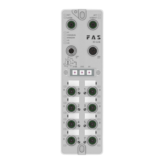
- Page 6 1 Mounting hole 8 Port 5 15 Port identification plate 2 Network port 2 status indicator 9 Port 7 16 Power input port 3 Network port 2 10 Port 6 17 Module indicator light 4 Power output port 11 Port 4 18 Network port 1 5 DIP switch 12 Port 2...
- Page 7 1.2 Mechanical connection The modules are connected using 2 M6 bolts and 2 washers. Isolation pads are available as accessories. 1.3 Electrical connection 1.3.1 Power interface (L-code) Definition of power input port Definition of power output port Power port System power Auxiliary power Function Description...
- Page 8 1.3.2 Network interface (D-code) Function Send data+ Receive data+ Send data- Receive data- Note: Unused I/O port sockets must be covered with end caps to meet IP67 protection rating. 1.3.3 I/O-port (A-code) Port0~Port3 definition: Function +24V (Brown) maximum current 1A Input /Output (White) 0V (Blue) Input/Output/IOLINK (Black)
- Page 9 1.3.4 Master module wiring method Independent power supply System power Auxiliary power In independent power supply mode, the maximum current of each master station can reach 16A. String power supply System power Auxiliary power In the serial power supply wiring mode, if the rear module needs to be connected to the front module, the cumulative current must not exceed 16A.
- Page 10 2.1 Size 2.2 Mechanical data Shell material Die-cast aluminum housing, pearl nickel plated Housing rating according to IEC 60529 IP67 Only when inserted or plugged) Power interface L-Code (male and female) Input port/output port M12, A-Code (8*Female) Size(W*H*D) 65mm*222mm*25.8mm Installation type 2-Through hole mounting Ground bus accessories Weight...
- Page 11 2.5 Network port Port 2 x 10Base-/100Base-Tx Port connection M12,D-Code IEEE 802.3 compliant cable types Shielded twisted pair, minimum STP CAT 5/STP CAT 5e Data transfer rate 10/100Mbit/s Maximum cable length 100m Flow control Half working condition/full working condition (IEEE 802.3-PAUSE) 2.6 Function indicator Green...
- Page 12 Green Output voltage is normal Flashing red Output voltage low (< 18 V) Red always on No output voltage present (< 11 V) Profinet communication protocol module status Show Function Closure Working fine Flashing red 3s 1HZ Bus start Red always on System error Cosure Working fine...
- Page 13 I/O port status State Function LED1 Closure The status of Pin4 input or output is 0 LED1 Yellow The status of Pin4 input or output is 1 LED1 Port configured as output: Pin4 short circuit LED1 Flashing red Pin1 short circuit LED1 Green IOLink is connected...
- Page 14 3.1 Module configuration 3.1.1 Restoring factory settings and switching communication protocols 14 / 31...
- Page 15 3.1.2 Network segment modification (only applicable to EIP and CCIEBS communication protocols) 15 / 31...
- Page 16 3.1.3 Setting the number of CCIEBS occupied stations 3.2 Data mapping EIP communication protocol process output data Function description Byte Function Bit7 Bit6 Bit5 Bit4 Bit3 Bit2 Bit1 Bit0 description Port3 Port2 Port1 Port0 Standard Pin4 Pin4 Pin4 Pin4 IO output 0=off Port3 Port2...
- Page 17 EIP communication protocol process input data Function description Byte Function Bit7 Bit6 Bit5 Bit4 Bit3 Bit2 Bit1 Bit0 description Standard IO input Port7 Port6 Port5 Port4 Port3 Port2 Port1 Port0 0=no signal Pin4 Pin4 Pin4 Pin4 Pin4 Pin4 Pin4 Pin4 1=There is signal Standard IO...
- Page 18 IO-Link PD is valid Port7 Port6 Port5 Port4 Port3 Port2 Port1 Port0 0=disabled 1=enable Overhe Module status Overvo Overvo Under Under ltage ltage voltage voltage Reserve Port 0 process input data 10-41 Port 1 process input data 42-73 Port 2 process input data 74-105 Port 3 process input data 106-137...
- Page 19 10 = keep the last value Port7 Port6 Port5 Port4 (1byte)IOLink CycleTime (1byte)Validation Type (2bytes)Vendor ID1~ID2 Byte configuration* Port0 (3bytes)Device ID1~ID3 (16bytes)Serial Number1~16 (1byte)Parameter Server Byte Port1 configuration* (Same as above) Byte Port2 configuration* (Same as above) Byte Port3 configuration* (Same as above) Byte Port4 configuration*...
- Page 20 Port configuration parameter description: A. (1byte) IOLink CycleTime cycle time setting: This parameter can be used for IO-Link communication speed. Using multipliers and time base calculations, the IO-Link cycle time can be increased. The time base is described in the table below. The multiplier is entered in decimal form from 0…63.
- Page 21 CCIEBS communication protocol process output data Function description Byte Function Bit7 Bit6 Bit5 Bit4 Bit3 Bit2 Bit1 Bit0 description Port7 Port6 Port5 Port4 Port3 Port2 Port1 Port0 Standard IO Pin4 Pin4 Pin4 Pin4 Pin4 Pin4 Pin4 Pin4 output 0=off Port7 Port6 Port5 Port4...
- Page 22 CCIEBS communication protocol process input data Function description Byte Function description Bit7 Bit6 Bit5 Bit4 Bit3 Bit2 Bit1 Bit0 Standard IO input Port7 Port6 Port5 Port4 Port3 Port2 Port1 Port0 0=No signal Pin4 Pin4 Pin4 Pin4 Pin4 Pin4 Pin4 Pin4 1=There is signal Standard IO input Port7...
- Page 23 Port 7 process input data Note: 1. Please set the CCIEBS master port function in the FAS IOLink Tool software. 2. Points of 64 occupy 1 station, and the slave station connected to each port uses 4 words of points.
- Page 24 3.3 PLC integration tutorial (The module communication protocol should be set before configuring the module, see 5.1.1 for details) 3.3.1 Siemens S7-1200 Portal Integration (PN) 1.Install GSD file 2.In PLC---Device Configuration---Network View---Hardware Catalog, select the module and drag it in, click "Unassigned", and select the PLC to be connected; 3.Double-click the module to enter the configuration.
- Page 25 (3)Module function configuration: Click the module icon, select "General", then click slot 0 to configure the module function (4)After the configuration is completed, click Download in the configuration view. 4. Assign module PN name: PLC switches to online state, select "Ungrouped Device"---Click the module name----Select Online and Diagnosis---Function-----Assign PROFINET device name-- --Select the module to be assigned in the list (should be selected based on the physical MAC) ---Click "Assign Name"...
- Page 26 3.3.2 Omron NX1P2 Sysmac Studio Integrated (EIP) 1. Install the EDS file: Tools---ETHERNET/IP connection settings---double-click the PLC in the window---right-click the blank space in the toolbox on the right and select "Show EDS Library", click "Install" in the pop-up window, and select EDS file installation 2.Create a module: Click "+"...
- Page 27 (3)In the built-in ETHERNET/IP port setting window--select the second icon on the left (connection)---click "+", select the previously configured module for the target device, select EXCLUSIVE Owner for the IO type, and select the corresponding For input and output, the target variable must be filled in 101,100;...
- Page 28 3.3.4 Mitsubishi FX5U Work2 integrated (CCIEBS) 1. Install the CCSP file: First open GX WORKS 3-Tools-Configuration File Management-Login-CSPP file (the project must be closed to import the file) 2.Click Project on the left - Parameters - FX5UCPU - Module parameters - Ethernet port, Basic settings - Self-node settings.
- Page 29 5. Automatic detection of connected devices - occupies 4 stations, IP address is set using DIP switch - reflects the setting and closes 6.To refresh the target, select the specified device-software name M-assign the device address-application, and the configuration is completed! 29 / 31...
- Page 30 ·4 blind plugs M12 ·Ground bus ·Thread M4x6 ·20 tags 4.2. Order code FNI MPL-50X-105-M FAS network interface Various industrial communication protocols Function 506=IP67IO-Link master module, 8IO-Link port Port~4-7 has no IO output 508=IP67IO-Link master module, 8IO-Link ports Version 105=Show version...
- Page 31 31 / 31...
Need help?
Do you have a question about the FNI MPL-506-105-M and is the answer not in the manual?
Questions and answers