Table of Contents
Advertisement
Quick Links
Advertisement
Table of Contents

Related Manuals for FAS FNI MPL-508-105-M


Summary of Contents for FAS FNI MPL-508-105-M
- Page 1 FNI MPL-508-105-M IO Link Master Module User Manual www.fas-elec.com...
-
Page 2: Table Of Contents
3.2. Mechanical connection 3.3. Electrical connections 4 Technical data 4.1. Size 4.2. Mechanical data 4.3. Operating conditions 4.4. Electrical data 4.5. Network port 4.6. Function indicator 5 Integrated 5.1 Module configuration 5.2 Data mapping 5.3 PLC Integration Tutorial 6 Appendix www.fas-elec.com... -
Page 3: Manual Structure
(eg: 00hex) or with the prefix "0X" (eg: 0x00) Cross reference Cross-references indicate where to find additional inform tion on this topic. 1.3.Symbol ----------------------------------------------------------- Notes This symbol indicates a general comment. Notice!! This symbol indicates the most important safety notice. www.fas-elec.com... -
Page 4: Safety
1.3. Acronym FAS network interface Standard input port Profinet EtherCAT CCIEBS CC-Link IE Field Basic Slave Ethernet/IP Electromagnetic Compatibility Functional ground Standard output port 1.5.Viewing angle deviation Product views and explanations in this manual m ay deviate from the actual product. They are on ly used left and right to explain the material. -
Page 5: Getting Started Guide
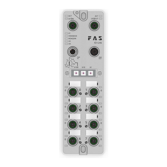
If the modul e fails or is damaged due to this corrosive medium, n o claim for defects can be claimed. ----------------------------------------------------- Dangerous voltage Precautions! Disconnect all power sources before using the equipment! ----------------------------------------------------- Getting Started Guide 3.1. Module overview www.fas-elec.com... -
Page 6: Mechanical Connection
6 Port 1 13 Port Status Indicators 20 Ground connection 7 Port 3 14 Port 0 3 Getting Started Guide 3.2. Mechanical connection The modules are attached using 2 M6 bolts and 2 washers. Isolation pads are available as accessories. www.fas-elec.com... -
Page 7: Electrical Connections
2. The FE connection from the housing to the machine must be low impedance and kept as short as possible. 3.3.2 Network Interface(D-code) Features Send data+ Receive data+ Send data- Receive data- Notes: Unused I/O port sockets must be covered with end caps to meet IP67 rating. www.fas-elec.com... -
Page 8: Technical Data
Technical data 4.1. Size 4.2 Mechanical data Shell material Die-cast aluminum case, pearl nickel plated Enclosure rating according to IEC 60529 IP67(Only in plug-in or plug-in style) Power interface L-Code(male and female) Input port/output port M12,A-Code(8* female) www.fas-elec.com... -
Page 9: Operating Conditions
EIP Communication Protocol Module Status Show Features Green light is always Working status: The device is running nor mally SF/MS/RU Green light flashes 1 Standby: Device not configured Green, red and green Self-test: The device is undergoing a pow www.fas-elec.com... - Page 10 No configuration; or slow physical link; or no physical link Green Input voltage is normal Flashing low input voltage (< 18 V) Green The output voltage is normal Flashing low output voltage (< 18 V) Red always No output voltage (< 11 V) www.fas-elec.com...
- Page 11 Port configured as output:Pin4 overcurrent Flashing red Port configured as output:Pin1 overcurrent Green IO Link connected Flashing IO Link not connected green Closure The status of Pin2 input or output is0 Yellow The status of Pin2 input or output is1 www.fas-elec.com...
-
Page 12: Integrated
X100=0:EI When the EIP protocol communication Default X100=1:EI protocol is EIP or 192.168.1. CIE, the last digit Dial X100=2:EI of the IP address CIE protocol will take effect Default X100=3:PN according to the www.fas-elec.com 192.168.3. X100=4:EC dial code Dial... - Page 13 The module is Wait for the PT X1=1: occupy powered off, dial indicator 1 station back the original Steady green X1=2: occupy module IP 2 stations address X1=3: occupy www.fas-elec.com 3 stations X1=4: occupy 4 stations...
-
Page 14: Data Mapping 1
Port 3 process output data 134 ~ 165 Port 4 process output data 166 ~ 197 Port 5 process output data 198 ~ 229 Port 6 process output data 230 ~ 261 Port 7 process output data EIP Protocol Process input data www.fas-elec.com... - Page 15 0=disabled 1=enable overhea module status overvolt overvolt undervol undervo tage ltage 8 ~ 9 Reserve 10 ~ 41 Port 0 process input data 42 ~ 73 Port 1 process input data 74 ~ 105 Port 2 process input data www.fas-elec.com...
- Page 16 01 = keep at 1 10 = keep last Port7 Port6 Port5 Port4 value Pin2 Security S Port3 Port2 Port1 Port0 tatus Settings 00 = keep at 0 01 = keep at 1 10 = keep last Port7 Port6 Port5 Port4 value www.fas-elec.com...
- Page 17 IO-Link communication speed is available for this parameter. Using multipliers and time base calculations, the IO-Link cycle time can be increased. The time base is described in the table below. The multiplier is entered in decimal form from 0… Possible values for MasterCycleTime and MiniCycleTime www.fas-elec.com...
- Page 18 Pin2 Pin2 (The remaining points are reserved) Port 0 process output data(32Byte) Port 1 process output data(32Byte) Port 2 process output data(32Byte) (maximum 256Byte) Port 3 process output data(32Byte) Port 4 process output data(32Byte) Port 5 process output data(32Byte) www.fas-elec.com...
- Page 19 1=Signal Short circuit detection Port7 Port6 Port5 Port4 Port3 Port2 Port1 Port0 (Pin1 Pin1 Pin1 Pin1 Pin1 Pin1 Pin1 Pin1 Pin1 overcurrent) 0=no signal 1=Signal IOLink communication status Port7 Port6 Port5 Port4 Port3 Port2 Port1 Port0 0=Not connected 1=Connected www.fas-elec.com...
-
Page 20: Plc Integration Tutorial
Port 7 process input data(32Byte) Note: 1. Please set the CCIEBS master port function in the FAS IOLink Tool software. 2. The number of points 64 occupies 1 station, and the number of points used by the slave station connected to each port is 4 words 3. - Page 21 2. Double-click the module to enter the configuration, (1) Slot function configuration: select the required data in the hardware catalog--module and drag it into the slot in the device overview window; (2) Module port function configuration: click the module icon, select "General", www.fas-elec.com...
- Page 22 5.3.2 OMRON NX1P2 Sysmac Studio Integration (EIP) 1. Install the EDS file: Tools---ETHERNET/IP Connection Settings---Double-click PLC in the window---right-click on the blank of the toolbox on the right and select "Show EDS Library", click "Install" in the pop-up window, and select EDS file installation www.fas-elec.com...
- Page 23 (2)In the built-in ETHERNET/IP port setting window - select the first icon (label) on the left - click "register all" (3)n the built-in ETHERNET/IP port setting window - select the second icon on the left (connection) - click "+", the target device selects the previously configured module, the IO type www.fas-elec.com...
- Page 24 3. Click on the left project-parameters-FX5UCPU-module parameters-Ethernet port, basic settings-self-node settings. Set the self-node IP 2. Click CC-Link IEF Basic Settings - select whether to use CC-Link IEF Basic - click Use 3. Click CC-Link IEF Basic settings - select network configuration settings - detailed settings; www.fas-elec.com...
-
Page 25: Appendix
2.Select the specified soft element for refresh target - soft element name M - assign soft element address - application, the configuration is complete! 6 Appendix 6.1. Materials included FNI MPL includes the following components · I/O-block ·4 blind plugs M12 ·Ground bus ·Thread M4x6 20 tags www.fas-elec.com... - Page 26 6.2. order code FNI MPL-50x-105-M FAS Network Interface Various industrial communication protocols Features 506= IP 67 IO-Link master module, 8 IO-Link ports Port4~7 no 10 outputs 508 = IP 67 IO-Link master module, 8 IO-Link ports Version 105 = show version...
Need help?
Do you have a question about the FNI MPL-508-105-M and is the answer not in the manual?
Questions and answers
用于西门子PLC组态的GSD文件
The GSD file for the FAS FNI MPL-508-105-M is used to integrate the module with a Siemens S7-1200 PLC in the TIA Portal. It enables the module to be added to the hardware catalog, configured in the network view, and assigned a PROFINET device name based on its MAC address.
This answer is automatically generated