Advertisement
Quick Links
Advertisement

Subscribe to Our Youtube Channel
Related Manuals for DriveTest BIA-600 BT


Summary of Contents for DriveTest BIA-600 BT
- Page 1 BIA-600 BT Manual...
- Page 3 Pinch Force Meter BIA-600 BT Contents General ......................3 Scope of Application ....................3 Product Description ....................3 Construction ......................5 Optional Modules ....................5 1.4.1 Spacers ........................5 1.4.2 Software ......................... 6 Technical Specifications ..................7 Safety Instructions ..................8 Target Group ......................
- Page 4 Pinch Force Meter BIA-600 BT Contact ........................20 Shutdown ....................20 Disposal ........................20 Appendix ..................... 21 EC certificate of conformity ................21 Glossary ........................22 List of figures ......................23 Version 1.0 Seite 2/23...
- Page 5 Pinch Force Meter BIA-600 BT 1 General 1.1 Scope of Application The force meter BIA-600 BT is used to measure the pinch force of power operated doors, gates and barriers. The device evaluates the measured results with respect to the requirements of...
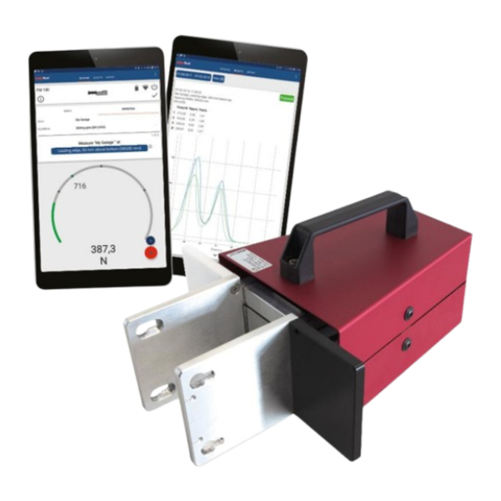
- Page 6 Pinch Force Meter BIA-600 BT Figure 1: BIA-600 BT Set Functions: Button (7) LED (8) USB socket (9) Figure 2: Device functions Version 1.0 Seite 4/23...
- Page 7 The norm DIN EN 14752:2015 requires to measure with several different apertures of the door system. These apertures are realized by spacers which are part of the BIA-600 BT set. By mounting different spacers all the required the apertures can be measured.
- Page 8 This ensures the correct relation from measurement to aperture. Figure 4: Spacers for BIA-600 BT We also offer a spacer equivalent to the aperture required for the former revision of the DIN EN 14752 norm (the smallest spacer in the figure).
- Page 9 Pinch Force Meter BIA-600 BT 1.5 Technical Specifications Description Value Mechanics: Spring stiffness 10 N/mm Accuracy of spring stiffness - 5 % to +5 % (lined force initiation) Gap width 90 mm Force initiation area 100 x 100 mm Overload protection Weight Approx.
- Page 10 Pinch Force Meter BIA-600 BT 2 Safety Instructions 2.1 Target Group The initial start-up and the operation of the device is restricted to professional personnel. This professional must have read and understood the content of this manual. Opening or disassembling of the device is restricted to Drive Test personnel due to safety and warranty reasons.
- Page 11 Pinch Force Meter BIA-600 BT Consider the package labelling requirements therefore by putting a label outside on the package looking like shown in Figure 5: Shipping label. The size should be min. 120mm x 110mm, on small boxes (where it does not fit on one side) it can be 105mm x 74mm.
- Page 12 Pinch Force Meter BIA-600 BT 2.4 Storing Please always store the device in a dry environment under the specified temperature (refer chapter 1.5 “Technical Specifications”). The battery should not be empty before storing and if stored for a longer period it has to be charged once in 6 months.
- Page 13 Pinch Force Meter BIA-600 BT Figure 6: Overview Android App Force Meter 4.2 Turning On Push the button on the device for approximately 1 second to turn it on (see “Functions”). During the start-up, the LED will be lightning in blue colour for a short period of time.
- Page 14 Pinch Force Meter BIA-600 BT After the device has finished the start-up procedure, the LED will change from blue lightning to pulsing blue state. This state indicates that the device is ready to connect. Flashing blue ➔ Ready to connect Permanently blue ➔...
- Page 15 Pinch Force Meter BIA-600 BT LED on the measuring device will change to permanently blue light and the Android App will show a symbol for “Connected”. 4.3.2 USB connection Connect the measuring device at the USB socket with the USB cable and connect the other side of the cable with your PC.
- Page 16 Pinch Force Meter BIA-600 BT case of two moving edges, choose one of the edges for the static part and follow the movement of this edge manually. Figure 10: Device positioning Closing systems with one moveable door Place one of the force initiation areas on the static part of the door without giving pressure to the sensor.
- Page 17 Pinch Force Meter BIA-600 BT Figure 11: Measuring points according to DIN EN 14752:2015 These measuring points are achieved by mounting spacers in the following way. Version 1.0 Seite 15/23...
- Page 18 Pinch Force Meter BIA-600 BT 90 mm 50 mm 400 N 130 mm 100 mm 300 N 230 mm 200 mm 300 N 340 mm 300 mm 400 N 400 N 560 mm 500 mm (600 N) The software detects the spacers automatically and stores the data to the corresponding measurement.
- Page 19 Pinch Force Meter BIA-600 BT 4.4.3 Start measuring The measurement is started by a short button press. Alternatively, it can be started through the software (either PC or Android device). During the measurement the LED shows a yellow light and the measured values are displayed in the software.
- Page 20 Pinch Force Meter BIA-600 BT The remaining battery in percentage will be displayed if you push the battery icon in the Android App (see chapter 4.1 “Function Overview Android App”). Connect the measuring device via the USB socket with the USB cable. Then connect the other plug with a USB power charger or PC/ Laptop.
- Page 21 Pinch Force Meter BIA-600 BT 5 Service 5.1 Calibration Drive Test devices are very precise instruments, but can be damaged by inappropriate treatment like dropping etc. To ensure proper function, we recommend an annual calibration (interval of one year). The calibration date and state appear on the report (calibration certificate).
- Page 22 Pinch Force Meter BIA-600 BT 5.4 Contact On our website you will find product descriptions to this and other products. Additionally, you will find video manuals and detailed FAQ to our products. Website: www.drivetest.de You can also reach us via e-mail or phone: Tel.:...
- Page 23 The manufacturer or of his representative is Drive Test GmbH Adi-Maislinger-Str. 9 81373 München Deutschland hereby certify that the device BIA-600 BT meets the intend of the applicable directives: 2014/35/EU Electrical equipment (low voltage) 2014/30/EU EMC 2011/65/EU RoHS Thomas Berger, CEO Munich, 22.11.2018...
- Page 24 Pinch Force Meter BIA-600 BT 7.2 Glossary The following glossary should serve as disambiguation and description of terms used in this manual. Term Meaning/ usage Degree to which the result of measurement conforms to the correct Accuracy value Gap width...
- Page 25 Figure 1: BIA-600 BT Set ......................4 Figure 2: Device functions ......................4 Figure 3: Device construction ....................5 Figure 4: Spacers for BIA-600 BT ................... 6 Figure 5: Shipping label......................8 Figure 6: Overview Android App Force Meter............... 11 Figure 7: Device after turning it on ..................
Need help?
Do you have a question about the BIA-600 BT and is the answer not in the manual?
Questions and answers