Table of Contents
Advertisement
Quick Links
Advertisement
Table of Contents

Related Manuals for DriveTest BIA 600


Summary of Contents for DriveTest BIA 600
- Page 1 BIA 600 Pinch Force Meter for Railway Doors (EN14752) Manual...
-
Page 2: Table Of Contents
Drive Test GmbH Munich Manual BIA600 Page 1 of 56 Inhalt GENERAL ....................5 PURPOSE OF USE ..................5 PROPER USE .................... 5 OLD DEVICES ................... 5 BATTERIES AND RECHARGEBLE BATTERIES ........5 TRANSPORT ..................... 5 SYSTEM ARCHITECTURE ................ 6 TETHERED .................... - Page 3 Drive Test GmbH Munich Manual BIA600 Page 2 of 56 7.5.1 Erase memory ..................14 7.5.2 Peak force limit ..................14 7.5.3 Mode of measurement ................15 ERROR MESSAGES ................15 DISPLAY UNIT MAINTENANCE .............. 15 BATTERY SEB2 ..................16 7.8.1 Battery load state ..................
- Page 4 Drive Test GmbH Munich Manual BIA600 Page 3 of 56 8.6.3 Sensor/ Configuration ................32 8.6.4 Operating bars ..................34 MEASURING WITH PINCHPILOT ............35 8.7.1 Normal operation ..................35 8.7.2 Controlled by PinchPilot ................35 SOFTWARE MAINTENANCE..............36 SOFTWARE PLUG-INS ................36 8.10 SEQUENCE OF MEASUREMENTS ............
- Page 5 Drive Test GmbH Munich Manual BIA600 Page 4 of 56 GUARANTEE ................... 54 CONTACT INFORMATION ..............54 APPENDIX ....................55 13.1 ERROR MESSAGES DISPLAY UNIT ............55 Version 5.2 Archive: Stamm_BIA600_EN_V5.2.docx...
-
Page 6: General
Drive Test GmbH Munich Manual BIA600 Page 5 of 56 GENERAL PURPOSE OF USE The purpose of use of the Force Meter BIA600 is to measure the closing force of power operated doors and evaluate the measured results with respect to the requirements of applicable standards (refer to chapter “Standards”). -
Page 7: System Architecture
Drive Test GmbH Munich Manual BIA600 Page 6 of 56 SYSTEM ARCHITECTURE TETHERED 2.1.1 Sensor - SEB2 2.1.2 Sensor - SEB2 - RS232 – Windows-PC (PinchPilot) 2.1.3 Sensor - SEB2.2 - USB – Windows-PC (PinchPilot) 2.1.4 Sensor - SEB2.2 - USB – Windows-PC (DLL) WIRELESS 2.2.1 Sensor-BT –... -
Page 8: Starting Up
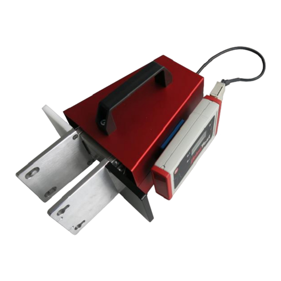
Drive Test GmbH Munich Manual BIA600 Page 7 of 56 STARTING UP BIA600-(TETHERED) 3.1.1 Determining completeness Sensor BIA600 Display unit SEB2 or SEB2.2 USB-cable, USB charger (SEB2.2) PinchPilot-software (USB Stick) Set of spacers (4 pieces) Manual, calibration certificate (placed in the cover of the transport case) Transport case Display Unit Spacer No. -
Page 9: Function Test
Drive Test GmbH Munich Manual BIA600 Page 8 of 56 3.1.2 Function test Load display unit battery via USB charger connect sensor to display unit, turn on the display unit by briefly pressing the display unit push button, after initialisation start a measurement by pressing the push button of the display unit, apply/remove load to sensor, force is displayed BIA600 BT (WIRELESS) 3.2.1 Determining completeness... -
Page 10: Pinch Force Sensor
Drive Test GmbH Munich Manual BIA600 Page 9 of 56 PINCH FORCE SENSOR BASIC CONSTRUCTION The instrument consists of a right and a left force initiation area of 100x100 mm. The link between the two parts is performed by a leaf spring system including a strain gauge Mechanical dimensions in mm Version 5.2 Archive: Stamm_BIA600_EN_V5.2.docx... -
Page 11: Spacer
Drive Test GmbH Munich Manual BIA600 Page 10 of 56 SPACER The EN14752:2015 standard requires to measure the closing force at different apertures. The BIA600 spacer set facilitates these measurements. The spacers can be mounted onto the BIA600 sensor without any tool. The applied spacers are automatically detected. -
Page 12: Calibration
Drive Test GmbH Munich Manual BIA600 Page 11 of 56 CALIBRATION Drive Test meters are very precise instruments, but can be easily damaged by inappropriate treatment like dropping etc. . To ensure proper function, calibration in intervals of one year is recommended. The calibration date and state appear on the report. -
Page 13: Display Unit Seb2 / Seb2.2
Drive Test GmbH Munich Manual BIA600 Page 12 of 56 DISPLAY UNIT SEB2 / SEB2.2 The display unit is used to display, evaluate and store the measurements. A short guide to measure is attached to the back of the display unit. The functions of the display unit are: Controlling measurements Storing measurements... -
Page 14: Memory Capacity
Drive Test GmbH Munich Manual BIA600 Page 13 of 56 The function of the operating button is different, according to the state of the display unit. In the “off” state the display unit can be turned on. In the “on” state the display unit can be turned off by pressing the button longer than two seconds. -
Page 15: Data Transfer
Drive Test GmbH Munich Manual BIA600 Page 14 of 56 DATA TRANSFER The display unit has to be connected to the USB port and is turned on by pressing briefly on the operating button. The data transfer is controlled by the PC software PinchPilot. -
Page 16: Mode Of Measurement
Drive Test GmbH Munich Manual BIA600 Page 15 of 56 7.5.3 Mode of measurement Precondition: selectable mode (PinchPilot: sensor/configuration/extended). Depending on the standard, a single, a dual or a triple measurement is required. An additional setting is the option “auto sequence”. In this case, the next measurement is started automatically. -
Page 17: Battery Seb2
Drive Test GmbH Munich Manual BIA600 Page 16 of 56 BATTERY SEB2 The SEB2 is equipped with a non rechargeable Alkaline battery. 7.8.1 Battery load state When the message „BAT“ is permanently indicated on the LCD display, it is time for a battery exchange. -
Page 18: Battery Seb2.2
Drive Test GmbH Munich Manual BIA600 Page 17 of 56 BATTERY SEB2.2 The display unit SEB2.2 is equipped with a rechargeable Lithium-Polymer battery. 7.9.1 Battery loading The battery is loaded via USB interface. Loading source can be either a PC or a USB charging device. -
Page 19: Transportation
Drive Test GmbH Munich Manual BIA600 Page 18 of 56 7.9.3 Transportation The display unit SEB 2.2 contains a Lithium-Polymer battery cell. These are classified as dangerous goods in transportation. As this is a build-in battery cell please follow guidelines UN3481 and respect your local law. -
Page 20: Seb2.2 Option: Analog Interface 0509
Drive Test GmbH Munich Manual BIA600 Page 19 of 56 7.10 SEB2.2 OPTION: ANALOG INTERFACE 0509 The optional analog interface 0509 is available only for SEB2.2 display unit. Features of the analog interface 0509 are: BNC output connector, isolated from display unit SEB2.2 Output of analog value during measurement Range: 0 –... -
Page 21: Settings
Drive Test GmbH Munich Manual BIA600 Page 20 of 56 7.10.2 Settings An initial setting is required before start of operation. This procedure has to be performed for each sensor separately: Connect sensor to display unit SEB2.2 Connect display unit SEB2.2 to PC Start PinchPilot In the menu go to “Sensor/ Configuration/ Extended”... -
Page 22: Measuring Seb2 / Seb2.2
Drive Test GmbH Munich Manual BIA600 Page 21 of 56 7.11 MEASURING SEB2 / SEB2.2 7.11.1 Preparation 7.11.1.1 Configuration Check configuration settings: Refer to chapter „Software PinchPilot/ PinchPilot settings/ Sensor/ Configuration“. 7.11.1.2 Measuring with display unit and sensor Display unit and sensor are required to perform measurements. Both have to be connected. -
Page 23: Load Measured Data Into Pc (Upload)
Drive Test GmbH Munich Manual BIA600 Page 22 of 56 For some reason a measurement may need to be repeated. Therefore, the decision step “measurement valid/ not valid” has been added: Valid: Press operating button shortly. The measurement will be stored. The display shows the next free memory number. -
Page 24: Short Operating Instructions
Drive Test GmbH Munich Manual BIA600 Page 23 of 56 7.11.7 Short operating instructions 7.11.7.1 Measuring Step Function Instruction Turn off Press operating button for longer than 2 sec. Connect sensor to display unit Turn on Briefly press operating button Set limit if needed Yellow LED flashes slowly Note... -
Page 25: Pc Software Pinchpilot
Drive Test GmbH Munich Manual BIA600 Page 24 of 56 PC SOFTWARE PINCHPILOT The software PinchPilot is capable to: Readout of measurement data stored in the display unit Graphical visualisation Calculation of important characteristic values Evaluation of measurements on the base of guidelines Creation of measurement reports and storage of measurement data Control measurements INSTALLATION... -
Page 26: Interface Setting Related To Display Unit
Drive Test GmbH Munich Manual BIA600 Page 25 of 56 8.1.4 Interface setting related to display unit Please follow these steps: Connect display unit to your PC (COM, USB) For Bluetooth interface install a connection via in Windows settings. Normally, the display device is automatically detected by the PC. If not, please check COM port of USB to serial converter on your PC: “Settings/ Control panel/ Device manager/ COM ports”... -
Page 27: Software Updates
Drive Test GmbH Munich Manual BIA600 Page 26 of 56 8.1.5 Software updates The update installation procedure is the same as the original installation. It is not necessary to uninstall the former version of PinchPilot. License key is located on the box of USB stick or you can get it via e-mail after downloading the software from our website. -
Page 28: Main Menu
Drive Test GmbH Munich Manual BIA600 Page 27 of 56 MAIN MENU After starting PinchPilot by double click on the PinchPilot icon the main menu is displayed: Menu bar: At the upper screen margin there is the menu bar. This bar offers access to all PinchPilot functions. -
Page 29: Properties
Drive Test GmbH Munich Manual BIA600 Page 28 of 56 8.5.3 Properties Properties of measurement data are important attributes like the name of the customer, point of measurement etc. All properties appear on the printed report. Without properties measurement data can be easily mixed up and has little information value. Properties are set under “File/ Properties“. -
Page 30: Single/ Double/ Triple/ Quintuple Measurement
Drive Test GmbH Munich Manual BIA600 Page 29 of 56 8.5.6 Single/ double/ triple/ quintuple measurement Depending on the setting “Sensor/ Configuration/ Mode“, a measurement data file can consist of one, two or three measurements. 8.5.7 Export Depending on the intended purpose, measurement data can be exported in different formats. The following options are offered under “File/ Export“: Text: Unformatted text, which can be imported by programs like MS Excel or MS Word. -
Page 31: Pinchpilot Settings
Drive Test GmbH Munich Manual BIA600 Page 30 of 56 PINCHPILOT SETTINGS PinchPilot offers versatile settings. The default software installation settings ensure reasonable values so that the user has to adapt very few values. 8.6.1 Extras/ Options Setting options and their meanings Submenu Value Meaning... -
Page 32: Extras/ Settings
Drive Test GmbH Munich Manual BIA600 Page 31 of 56 Automation Move measurement Valid for automation mode automatically Upload previous Automation Valid for automation mode measurement automatically Text export Measuring distance Time between measurements Result export File format CSV or Q-DAS Result report Automatic export On/off, file path... -
Page 33: Sensor/ Configuration
Drive Test GmbH Munich Manual BIA600 Page 32 of 56 8.6.3 Sensor/ Configuration Important: For configuring the sensor, the display unit has to be connected to the PC and the sensor has to be connected to the display unit. The display unit has to be turned on. The configuration setting is stored in the display unit or in the connector of the sensor. - Page 34 Drive Test GmbH Munich Manual BIA600 Page 33 of 56 Version 5.2 Archive: Stamm_BIA600_EN_V5.2.docx...
-
Page 35: Operating Bars
Drive Test GmbH Munich Manual BIA600 Page 34 of 56 Limit value selectable: Enables/ disables limit modification during power on sequence. Selectable Mode: Enables/ disables mode selection during power on sequence. Measurement output (requires the optional analog interface): Enables/ disables output and defines force range. 8.6.4 Operating bars The menu bar and the tool bar may be customized by the user. -
Page 36: Measuring With Pinchpilot
Drive Test GmbH Munich Manual BIA600 Page 35 of 56 MEASURING WITH PINCHPILOT 8.7.1 Normal operation To carry out a normal measurement, the sensor and the display unit are the components in use. It is not necessary, to connect the display unit to a PC. The measurement procedure is described in the chapter “Measuring”. -
Page 37: Software Maintenance
Drive Test GmbH Munich Manual BIA600 Page 36 of 56 For settings for measuring mode please see the following table (Tab. 5.3): Tab. 5.3: Settings for measuring mode Setting Meaning Selectable values Limit Limit to be used Limit designation Autom. Upload Automatic upload at the end Active/ not active of a measurement... -
Page 38: Sequence Of Measurements
Drive Test GmbH Munich Manual BIA600 Page 37 of 56 File format: Standard setting is CSV format. Further processing with MS Excel is possible. An alternative format is Q-DAS. Automatic Export: The automatic export is performed during uploading of measured data from display unit. Details can be set in this menu. -
Page 39: Templates
Drive Test GmbH Munich Manual BIA600 Page 38 of 56 Transfer of sequence properties into the property fields of all measurements. The content of remarks is an exception. It appears only in the remarks field of the report. Application of the guideline and the limits for all measurements. A printable table is now available which can be inspected (previewed) on the screen. -
Page 40: Options Of Sequences
Drive Test GmbH Munich Manual BIA600 Page 39 of 56 8.10.3 Options of sequences 4-Lines vs. 1-Line: In case of triple measurements, the 4-lines representation makes sense. The table contains the results of all three measurements plus the average values. The alternative is the 1-line representation. -
Page 41: Change Of Guidelines
Drive Test GmbH Munich Manual BIA600 Page 40 of 56 Query: In case of danger of data loss, a message appears and offers the possibility to cancel the required action. This warning message can be suppressed. Report: In case of three or less single measurements a graphic presentation can be activated in addition to the result table. -
Page 42: Software Evaluation
Drive Test GmbH Munich Manual BIA600 Page 41 of 56 8.12 SOFTWARE EVALUATION Typical force flow. Es gilt: max. force < F perm PinchPilot shows the result table: F / N(F ), F / N and T / s:: peak force, F effective force, T pulse duration. -
Page 43: Guidelines, Standards
Drive Test GmbH Munich Manual BIA600 Page 42 of 56 GUIDELINES, STANDARDS The expressions used in this manual are defined as follows: Standard: General term for a directive for measuring and evaluating the closing force. This can be laws, European standards etc. . Guideline: Referred to as a set of parameters and limit values that define the execution of measurements and the way the results are tested. -
Page 44: General Definition Of Terms
Drive Test GmbH Munich Manual BIA600 Page 43 of 56 GENERAL DEFINITION OF TERMS Trigger threshold (Ft): A force above the trigger threshold starts the measurement. Peak force (Fp): Maximum force to be found during the measurement. Effective force (Fe): Average force during time T. -
Page 45: Test Methods
Drive Test GmbH Munich Manual BIA600 Page 44 of 56 EN14752:2015 EN14752:2015 is a European standard for Railway application - Bodyside entrance systems, released in2015. 9.2.1 Test methods 9.2.1.1 Position of vehicle The vehicle must be in horizontal position. 9.2.1.2 Number of measurements per measuring point For each measuring point at least three measurements have to be performed. - Page 46 Drive Test GmbH Munich Manual BIA600 Page 45 of 56 9.2.2.1 Test criteria Permissible peak force Force (N) Aperture at limit force (mm) Aperture Setting Setting left side right side Initial Width Limit Width, Limit Force Compressed uncompressed Fp perm (force = 0 N) S perm (force = limit)
-
Page 47: Spacer Detection
Drive Test GmbH Munich Manual BIA600 Page 46 of 56 9.2.3 Spacer detection The applied spacers are detected and the appropriate value is entered automatically. Manual spacer setting: After turning on the display unit, the actual limit width is displayed for a time of 2 seconds. -
Page 48: Sensor Width
Drive Test GmbH Munich Manual BIA600 Page 47 of 56 EN14752:2005 EN14752:2005 is a European standard for Railway application - Bodyside entrance systems. 9.5.1 Sensor width EN14752:2005 requires a sensor width of 115 mm. The BIA600 sensor width is 90 mm. Therefore a spacer of 25mm is required (BIA600-BT-FX-25). -
Page 49: Evaluation Display Unit
Drive Test GmbH Munich Manual BIA600 Page 48 of 56 9.5.4 Evaluation display unit Only valid for triple measurement with auto sequence ! max. Force < Fp perm effective force of 1st measurement < Fe perm clamping force FE < FE perm pulse duration <= 5 s 9.5.5 Evaluation PinchPilot The evaluation is identical with the one of the display unit. -
Page 50: Abs. 5 Stvzo
Drive Test GmbH Munich Manual BIA600 Page 49 of 56 §35E, ABS. 5 STVZO §35e, Abs.5 StVZO is a German law for power operated bus doors. 9.6.1 Test methods 9.6.1.1 Position of vehicle The vehicle must be in level position. 9.6.1.2 Number of measurements per measuring point For each measuring point three measurements have to be performed. -
Page 51: Evaluation Display Unit
Drive Test GmbH Munich Manual BIA600 Page 50 of 56 9.6.2.1 Test criteria Permissible peak force Fp perm, Permissible effective force FE perm: Effective Force Edge Peak force Fp perm F E perm Main closing edge 200 N 150 N Side closing edge (only with existing 250 N... -
Page 52: En14752-Db
Drive Test GmbH Munich Manual BIA600 Page 51 of 56 EN14752-DB The PinchPilot guideline EN14752-DB has been provided for the requirements of Deutsche Bahn. It mainly matches with EN14752:2005 but allows a series of higher limits for the effective force of the first measurement. Peak force Effective force Averaged effective... -
Page 53: Technical Data
Drive Test GmbH Munich Manual BIA600 Page 52 of 56 10. TECHNICAL DATA Technical specifications subject to change without notice. 10.1 SENSOR Größe Wert Spring deflection rate 10 N/mm Tolerance of deflection rate - 5% .. +5% 90 mm Force initiation area 100x100 mm Overload protection Weight... -
Page 54: Analog Interface (Optional, Only For Seb2.2)
Drive Test GmbH Munich Manual BIA600 Page 53 of 56 10.5 ANALOG INTERFACE (OPTIONAL, ONLY FOR SEB2.2) Größe Wert Connector BNC, female Output isolation 5000 VRMS 4 … 4000 mV Output voltage range Resolution 1 mV Sample rate 250 oder 500 S/s Force range;... - Page 55 The liability of Drive Test is limited to the repair of the delivered equipment. Further liability is excluded. 12. CONTACT INFORMATION Drive Test GmbH Adi-Maislinger-Str. 9 81373 Munich Germany Phone: +49 89 7434094-0 Fax: +49 89 7434094-9 E-mail: info@drivetest.de Website: www.drivetest.de Version 5.2 Archive: Stamm_BIA600_EN_V5.2.docx...
- Page 56 Drive Test GmbH Munich Manual BIA600 Page 55 of 56 13. APPENDIX 13.1 ERROR MESSAGES DISPLAY UNIT Display Service Meaning E:0x Protocol error E:1x Serial interface error (x: Bit0=Parity, Bit1=Framing, Bit2=Overflow) E:18 Baudrate error E:20 Sensor connector change E:21 Wrong sensor (version conflict) E:30 Sensor supply error Bit0=IES invalid, Bit1=IES instable, Bit2=DMS invalid, Bit3=DMS instable, Bit4=timeout...
Need help?
Do you have a question about the BIA 600 and is the answer not in the manual?
Questions and answers