Table of Contents
Advertisement
Quick Links
Advertisement
Table of Contents

Related Manuals for DriveTest FM300BT


Summary of Contents for DriveTest FM300BT
- Page 1 FM300BT ANUAL...
-
Page 3: Table Of Contents
Pinch Force Meter FM300BT English version Contents General ......................5 Scope of Application ....................5 Product Description ....................5 Construction ......................7 Optional Modules ....................8 1.4.1 Spacers ........................8 1.4.2 Software ......................... 9 Technical Specifications ..................10 Safety Instructions ..................11 Target Group ...................... - Page 4 Pinch Force Meter FM300BT Service ......................21 Calibration ........................ 21 Maintenance ......................21 Warranty ........................21 Contact ........................22 Shutdown ....................22 Disposal ........................22 Appendix ..................... 23 EC certificate of conformity ................23 Glossary ........................24 List of figures ......................25 Version 1.5...
-
Page 5: General
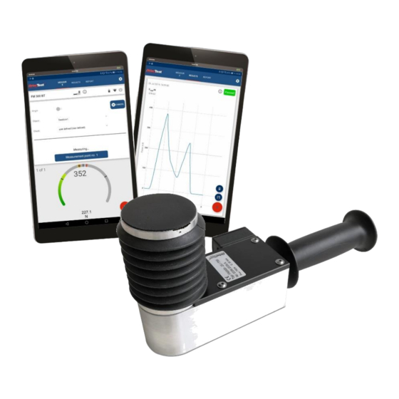
Pinch Force Meter FM300BT 1 General 1.1 Scope of Application The force meter FM300BT is used to measure the pinch force of power operated elevator doors and machinery protection systems. The device evaluates the measured results with respect to the requirements of... - Page 6 Pinch Force Meter FM300BT Figure 1: FM300BT Set Functions: Button (7) LED (8) USB socket (9) Figure 2: Device functions Version 1.5 Seite 6/23...
-
Page 7: Construction
Pinch Force Meter FM300BT 1.3 Construction The device consists of a static and a moveable part. Both parts are linked by a strain gauge sensor and a spring with a defined stiffness of 25 N/mm. The housing of the device is made of aluminium. The force initiation area with a diameter of 58 mm is on the upper side. -
Page 8: Optional Modules
A set of spacers is optionally available. The spacers are mounted on the static part the device at the bottom side. There are no tools required to mount the spacers. Figure 4: Spacers 1, 2, 3 and 4 for the FM300BT Version 1.5 Seite 8/23... -
Page 9: Software
Pinch Force Meter FM300BT The spacer set includes the following parts: Spacer 1: 20 mm Spacer 2: 50 mm Spacer 3: 100 mm Spacer 4: 200 mm With these spacers the following apertures can be measured: Total aperture 140 mm... -
Page 10: Technical Specifications
Pinch Force Meter FM300BT 1.5 Technical Specifications Description Value Mechanics: Spring stiffness 25 N/mm Accuracy of spring stiffness - 10 % to +10 % (lined force initiation) Gap width 140 mm Force initiation area 58 mm diameter Overload protection Weight approx. -
Page 11: Safety Instructions
Pinch Force Meter FM300BT 2 Safety Instructions 2.1 Target Group The initial start-up and the operation of the device is restricted to professional personnel. This professional must have read and understood the content of this manual. Opening or disassembling of the device is restricted to Drive Test personnel due to safety and warranty reasons. -
Page 12: Operation
Pinch Force Meter FM300BT Consider the package labelling requirements therefore by putting a label outside on the package looking like shown in Figure 5: Shipping label. The size should be min. 120mm x 110mm, on small boxes (where it does not fit on one side) it can be 105mm x 74mm. -
Page 13: Storing
Pinch Force Meter FM300BT 2.4 Storing Please always store the device in a dry environment under the specified temperature (refer chapter 1.5 “Technical Specifications”). The battery should not be empty before storing and if stored for a longer period it has to be charged once in 6 months. -
Page 14: Function Overview Android App
Pinch Force Meter FM300BT 4.1 Function Overview Android App (Change) current screen Open settings Display current device state (in connected state) Disconnect and turn off device Remaining battery Bluetooth connection quality Test (guideline/directive) settings (Change) instruction to the current measuring guideline... -
Page 15: Turning On
Pinch Force Meter FM300BT 4.2 Turning On Push the button on the device for approximately 1 second to turn it on (see “Functions”). During the start-up, the LED will be lightning in blue colour for a short period of time. -
Page 16: Usb Connection
Pinch Force Meter FM300BT Start the App Force Meter on your Android device and hit the connect symbol to connect to the sensor (see chapter Fehler! Verweisquelle konnte nicht gefunden werden. “Fehler! Verweisquelle konnte nicht gefunden werden. App”). The LED on the measuring device will rapidly blink in blue colour during establishing the connection. -
Page 17: Device Positioning
Pinch Force Meter FM300BT 4.4 Measuring The measuring device has to be turned on and connected via Bluetooth or USB to perform a measurement. 4.4.1 Device positioning The instrument is to be used such that the static part is connected to the stop of the closing system and the movable part faces towards the moving edge. -
Page 18: Mounting Spacers
Pinch Force Meter FM300BT Figure 11: Best force application area Axis of symmetry Force initiation Closing systems with one moveable door: Place one of the force initiation areas on the static part of the door without giving pressure to the sensor. The opposite force initiation area is facing the moveable part of the closing system. -
Page 19: Turning Off
Pinch Force Meter FM300BT specific norms. This point is related to the applied norm and is therefore optional (refer chapter 1.4.1 “Spacers” and chapter 3.2 “Assembly of Spacers”). 4.4.3 Start measuring The measurement is started by a short button press. Alternatively, it can be started through the software (either PC or Android device). -
Page 20: Charging
Pinch Force Meter FM300BT 4.6 Charging The LED on the measuring device will give feedback about the remaining battery in certain cases. If the LED is showing a permanently red LED after turning it on then the device has to be charged. -
Page 21: Errors
Pinch Force Meter FM300BT Permanently green ➔ Device fully charged Figure 14: LED battery state (fully charged) Depending on the current battery charging state it will take up to 4 hours to fully charge the device. 4.7 Errors If an error occurs then the LED will flash rapidly in red colour. After 5 seconds the device will automatically turn off. -
Page 22: Warranty
Pinch Force Meter FM300BT forces than specified (refer chapter 1.5 “Technical Specifications”) are applied to the device then there is a high risk of damaging it. 5.3 Warranty The manufacturer grants the buyer a two years warranty. Beginning of the warranty time is the delivery date (date of delivery note). -
Page 23: Contact
Pinch Force Meter FM300BT 5.4 Contact On our website you will find product descriptions to this and other products. Additionally, you will find video manuals and detailed FAQ to our products. Website: www.drivetest.de You can also reach us via e-mail or phone: Tel.:... -
Page 24: Appendix
The manufacturer or of his representative is Drive Test GmbH Adi-Maislinger-Str. 9 81373 München Deutschland hereby certify that the device FM300BT meets the intend of the applicable directives: 2014/35/EU Electrical equipment (low voltage) 2014/30/EU EMC 2011/65/EU RoHS Thomas Berger, CEO Munich, 23.07.2019... -
Page 25: Glossary
Pinch Force Meter FM300BT 7.2 Glossary The following glossary should serve as disambiguation and description of terms used in this manual. Term Meaning/ usage Degree to which the result of Accuracy measurement conforms to the correct value Gap width Also referred to as: opening width... -
Page 26: List Of Figures
Figure 1: FM300BT Set ....................... 6 Figure 2: Device functions ......................6 Figure 3: Device construction ....................7 Figure 4: Spacers 1, 2, 3 and 4 for the FM300BT ............. 8 Figure 5: Shipping label......................11 Figure 6: Overview Android App Force Meter............... 14 Figure 7: Device after turning it on ..................
Need help?
Do you have a question about the FM300BT and is the answer not in the manual?
Questions and answers