Advertisement
Quick Links
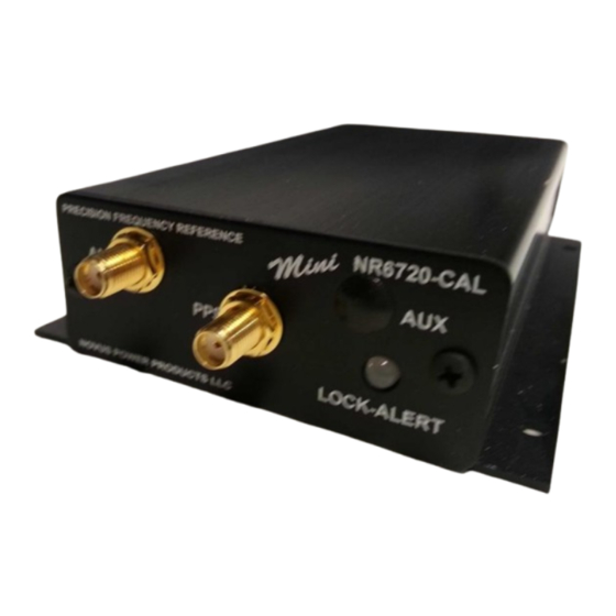
GPS Locked Reference Module
OCXO Holdover-GPSDO/ with Auto-Cal
All information provided herein is the proprietary property of Novus Power Products L.L.C. The
information included may be reproduced without the permission of Novus Power Products L.L.C. without
for the purpose of operating the Novus equipment.
Page #:
1 of 15
Users manual
Revision #:
Date:
NR6720-A6
www.novuspower.com
NR6720-A6
A
111020
Advertisement

Related Manuals for Novus NR6720-CAL


Summary of Contents for Novus NR6720-CAL
- Page 1 GPS Locked Reference Module OCXO Holdover-GPSDO/ with Auto-Cal All information provided herein is the proprietary property of Novus Power Products L.L.C. The information included may be reproduced without the permission of Novus Power Products L.L.C. without for the purpose of operating the Novus equipment.
- Page 2 Users manual NR6720-A6 Revision #: Date: 111020 Table of Contents Contents 1.0 Overview ........................3 2.0 Crystal .......................... 6 3.0 GPS Receiver ......................6 4.0 Input/Output Connectors/Mechanical ..............6 5.0 Typical Phase Noise ....................10 6.0 Alerts-Function Relay ....................10 7.0 GPS Function ......................
- Page 3 Users manual NR6720-A6 Revision #: Date: 111020 1.0 Overview The NR6720-A6 is a richly featured frequency reference that features: A high performance GNSS locked 10 MHz reference NMEA port to provide NMEA-0183 at user selectable rates and function PPS source available as CMOS or LVDS LVDS port available that can source PPS or 10 MHz Auxiliary frequency synthesizer from a 16 bit match counter Power from -60 to +60 Vdc in three ranges with AC adapter available.
- Page 4 Users manual NR6720-A6 Revision #: Date: 111020 GNSS locked OCXO 10 MHz frequency reference with PPS, RS232 and an optional secondary channel that can be factory programmed from 14 KHz to 10 MHz. The unit features Auto-Calibration such that the most recent coefficients to compensate the OCXO for drift due to aging and/or temperature are stored and applied to the OCXO during GPS loss of lock conditions.
- Page 5 AC power. Also, Novus offers related NR6720 products that can operate anywhere from – 60 to +60 Vdc. Contact the factory for further details. There is a PCB assembly version of this product (NR4300) which offers essentially the same functionality and can be directly embedded in a system - smaller size and lower cost.
- Page 6 Users manual NR6720-A6 Revision #: Date: 111020 2.0 Crystal The heart of the unit is a low phase noise SC cut crystal. The OCXO is a SC (stress compensated) crystal placed in an oven that is operated at about 10C above the maximum specified temperature.
- Page 7 Users manual NR6720-A6 Revision #: Date: 111020 2. PPS Output 3. Auxiliary output sma 4. RS232 DB9 NMEA 5. Power 6. 10 MHz output sma Page #: 7 of 15 www.novuspower.com...
- Page 8 Users manual NR6720-A6 Revision #: Date: 111020 Pin assignments Page #: 8 of 15 www.novuspower.com...
- Page 9 Users manual NR6720-A6 Revision #: Date: 111020 1. + positive power 2. – Power Return The 5 Vdc unit is designed to operate from 5Vdc nominal power (THE UNIT IS NOT REVERSE POLARITY PROTECTED). Units configured to operate from 9 Vdc and above incorporate reverse polarity protection.
- Page 10 Users manual NR6720-A6 Revision #: Date: 111020 5.0 Typical Phase Noise 10MHz Sine- Primary Output Offset Frequency (Hz) Typical (dBc / Hz) -130 -145 -150 -150 There are optional phase noise performance levels available - contact factory. 6.0 Alerts-Function Relay There are a number of critical circuits in the unit.
- Page 11 Users manual NR6720-A6 Revision #: Date: 111020 position fix. The receiver can operate in 2-D mode if it goes down to seeing only 3 satellites by assuming its height remains constant. But this assumption can lead to very large errors, especially when a change in height does occur. A 2-D position fix is not considered a good or accurate fix;...
- Page 12 Users manual NR6720-A6 Revision #: Date: 111020 This LED illuminates green when the unit is locked to the GPS system. If the LED is red, the unit is operating on the OCXO. The GPS lock status is on the RS232 connector. If the GPS indicator remains RED for an extended period of time, it could be an indication of an antenna, cabling or unit malfunction.
- Page 13 Tracking: -157 dBm Hot Start: -157 dBm Warm Start: -143 dBm Cold Start: -143 dBm Reacquisition: -157 dBm With Novus recommended antenna Antenna with LNA Antenna power 3.5 Vdc, < 35 ma (on center conductor) (factory configurable to 5 Vdc) Frequency...
- Page 14 Should Novus be unable to repair or replace the product within a reasonable amount of time, the customer’s alternate remedy shall be a refund of the purchase price upon return of the product to Novus. The liability of NOVUS under this warranty is limited to replacing, repairing or issuing a credit, at its option, for any such item returned by Buyer under the terms of this warranty.
- Page 15 Users manual NR6720-A6 Revision #: Date: 111020 10.0 Appendix A – NMEA, Radio Control and Status Page #: 15 of 15 www.novuspower.com...
- Page 16 GPS/GNSS Receiver Communications Specification NMEA-0183 All information provided herein is the proprietary property of Novus Power Products L.L.C. The information included may be reproduced without the permission of Novus Power Products L.L.C. without prior approval for purpose of operating the equipment.
- Page 17 Users manual Appendix A Revision #: Date: 07-14-15 Table of Contents: COMMUNICATION SPECIFICATION ......................... 4 SERIAL DATA OUTPUT TIMING △4........................... 5 NMEA SENTENCE FORMAT ............................. 6 PROPRIETARY SENTENCE FORMAT: ........................7 STANDARD NMEA OUTPUT SENTENCES ........................8 GGA – G : ......................
- Page 18 Users manual Appendix A Revision #: Date: 07-14-15 PROPRIETARY NMEA OUTPUT SENTENCES ......................40 ACK – O : ......................40 UTPUT THE OMMAND ECEPTION HECK ORMAT CR – ERIDE GNSS CORE LIBRARY INTERFACE ...................... 41 ) △4△5 F CRW(TPS1) – O : ..........
- Page 19 Users manual Appendix A Revision #: Date: 07-14-15 Communication Specification Signal Lines used: TXD, RXD Flow Control: None System: Full Duplex Asynchronous Speed: Configurable, Default 38400 bps (*1) Start Bit: 1 bit Data Length: 8 bits Stop Bit: 1 bit Parity Bit: None Data Output Interval:...
- Page 20 Users manual Appendix A Revision #: Date: 07-14-15 Serial data output timing △ The output timing of serial data is synchronous with PPS output timing. Serial data is begun to output in the 25ms to 75ms range after PPS is output. The time of serial data indicates next PPS output timing.
- Page 21 Users manual Appendix A Revision #: Date: 07-14-15 NMEA Sentence Format 13.1 Standard Sentence Format: <address field> <data field> … *<checksum field> <CR> <LF> 5 bytes Field Description Start-of Sentence marker <address field> 5-byte fixed length. First 2 bytes represent a talker ID, and the remaining 3 bytes do a sentence formatter.
- Page 22 Users manual Appendix A Revision #: Date: 07-14-15 Proprietary Sentence Format: $ P <maker ID> <sentence type> , <data field> … *<checksum field> <CR> <LF> 3 bytes 3 bytes Field Description Start-of-Sentence marker Proprietary sentence identifier 3-byte fixed length. <maker ID> GT-87’s maker ID is “ERD”...
- Page 23 Users manual Appendix A Revision #: Date: 07-14-15 Standard NMEA Output Sentences The receiver supports eight standard NMEA output sentences (GGA, GLL, GNS, GSA, GSV, RMC, VTG and ZDA) per NMEA standard 0183 Version 4.10 (June, 2012). By default, the RMC, GNS, GSA, ZDA, GSV and TPS sentences will be output every second. The sentences can be independently enabled and disabled using the $PERDCFG,NMEAOUT and/or $PERDAPI,CROUT command described later in this document, as well as use differing transmission rates.
- Page 24 Users manual Appendix A Revision #: Date: 07-14-15 – Global Positioning System Fix Data Format: $XXGGA , hhmmss.sss , ddmm.mmmm , , dddmm.mmmm , <CR> <LF> Description Range “hh”: hour 00 - 23 “mm”: minute 00 - 59 “ss.sss”: second 00.000 - 59.999 2-3.
- Page 25 Users manual Appendix A Revision #: Date: 07-14-15 – △ Geographic Position - Latitude/Longitude Format: $XXGLL , ddmm.mmmm , a , dddmm.mmmm , , hhmmss.sss , a , a *hh <CR> <LF> Description Range 1-2. Latitude “dd”: degree 00 - 90 “mm.mmmm”: minute 00.0000 - 59.9999 “a”: North/South...
- Page 26 Users manual Appendix A Revision #: Date: 07-14-15 – GNSS Fix Data Format: $XXGNS , hhmmss.sss , ddmm.mmmm , , dddmm.mmmm , , c--c , <CR> <LF> Description Range “hh”: hour 00 - 23 “mm”: minute 00 - 59 “ss.sss”: second 00.000 - 59.999 Latitude 2-3.
- Page 27 Users manual Appendix A Revision #: Date: 07-14-15 △ – GNSS DOP and Active Satellites Format: $XXGSA , a , a , xx , xx , xx , … , xx , x.x , x.x , x.x , h *hh <CR> <LF> 6-13 Description Range...
- Page 28 Users manual Appendix A Revision #: Date: 07-14-15 △ – GNSS Satellites in View Format: $XXGSV <CR> <LF> Description Range Total number of messages 1 - 4 Number of messages 1 - 4 Number of satellites in line-of-sight 00 - 14 Sat.
- Page 29 Users manual Appendix A Revision #: Date: 07-14-15 Satellite number from 93 to 99 indicates QZSS (193 to 199) Page 14 of 58...
- Page 30 Users manual Appendix A Revision #: Date: 07-14-15 △ – Recommended Minimum Navigation Information Format: $XXRMC , hhmmss.sss , a , ddmm.mmmm , a , dddmm.mmmm , a , x.x , , ddmmyy , <CR> <LF> # Description Range “hh”: hour 00 - 23 “mm”: minute 00 - 59...
- Page 31 Users manual Appendix A Revision #: Date: 07-14-15 Example: $GNRMC,012344.000,A,3442.8266,N,13520.1233,E,0.00,0.00,191132,,,D,V*0B UTC: 01:23:44.000 Differential 34 deg 42.8266 min N 135 deg 20.1233 min E Speed: 0.0 kts True Course: 0.0 degrees UTC Date: Nov 19, 2032 Page 16 of 58...
- Page 32 Users manual Appendix A Revision #: Date: 07-14-15 – Course Over Ground and Ground Speed Format: $XXVTG , *hh <CR> <LF> # Description Range 1-2. True Course (degree) “T” (meaning TRUE) 3-4. Magnetic Direction “M” (meaning Magnetic Direction) Note: A null field is output unless magnetic direction information is available. 5-6.
- Page 33 Users manual Appendix A Revision #: Date: 07-14-15 Proprietary NMEA Input Sentences These sentences are input commands for the protocol of this receiver. Page 18 of 58...
- Page 34 Users manual Appendix A Revision #: Date: 07-14-15 △ △ – GNSS Satellite System Configuration Format: $PERDAPI , GNSS , talkerID , , glonass , galileo , qzss sbas *hh <CR> <LF> Contents Range Default Remark GNSS Command Name AUTO: GLGSV is omitted in case of no glonass. AUTO, GPGSV is omitted in case of no GPS, SBAS and LEGACYGP...
- Page 35 Users manual Appendix A Revision #: Date: 07-14-15 △ – FIXMASK Setting of Positioning and Satellite Mask Format: $PERDAPI , FIXMASK , mode elevmask , Reserve1 snrmask , Reserve2 [, Prohibit SVs Prohibit SVs Prohibit SVs Prohibit SVs Prohibit SVs *hh <CR>...
- Page 36 Users manual Appendix A Revision #: Date: 07-14-15 Example: $PERDAPI,FIXMASK,USER,10,0,37,0,0x92,0x01,0x00,0x00,0x20000*50 Elevation mask: 10 degrees Signal level mask: 37 dBHz GPS mask: GPS (BIT2 = SVID 2), GPS (BIT5 = SVID 5) and GPS (BIT9 = SVID 9) GLONASS mask: GLONASS (BIT1 = SVID 65) SBAS mask: SBAS (BIT18 = SVID 50) Notes: - It is applied not only to First Fix or the time of a positioning return but to all the positioning.
- Page 37 Users manual Appendix A Revision #: Date: 07-14-15 ( ) – △ Setting of PPS Pulse per second 4 Format: $PERDAPI , PPS , type , mode , period , pulse width , cable delay , polarity [, PPS accuracy threshold] *hh <CR <LF>...
- Page 38 Users manual Appendix A Revision #: Date: 07-14-15 Notes: △ - LEGACY PPS setting is output legacy PPS which is not synchronized with frequency which is output from GCLK pin, but which is output immediately after first fix in case of cold start. - GCLK PPS setting is output GCLK PPS which synchronized with frequency which is output from GCLK pin, but it takes some to become GCLK PPS steady after first fix (typically, 1~2 minutes after fist fix).
- Page 39 Users manual Appendix A Revision #: Date: 07-14-15 △ RESTART - Restart command 4 Format: $PERDAPI , RESTART , restart mode *hh <CR> <LF> Contents Range Default Remark RESTART Command Name restart WARM Restart mode mode COLD FACTORY Example: $PERDAPI,RESTART,COLD*08 Mode: cold restart Notes: △...
- Page 40 Users manual Appendix A Revision #: Date: 07-14-15 – △ TIME Setting of time information Initial time is configured. The setting of time is effective only within the case that time is not decided by other factors. A setting of a millennium which is the times of GPS week rollover is received also after time decision.
- Page 41 Users manual Appendix A Revision #: Date: 07-14-15 – △ TIMEZONE Local Zone Time This sentence is reflected to ZDA sentence (not only local zone field but also UTC time field). Format: $PERDAPI TIMEZONE , sign , hour , minute *hh <CR> <LF> Contents Range Default...
- Page 42 Users manual Appendix A Revision #: Date: 07-14-15 – △ SURVEY Position Mode 1 Format: $PERDAPI , SURVEY , position mode [, sigma threshold , time threshold] latitude longitude altitude]] *hh <CR> <LF> Contents Range Default Remark SURVEY Command Name 0: Normal NAV (navigation) mode 1: Position Survey...
- Page 43 Users manual Appendix A Revision #: Date: 07-14-15 Fixed position: 37.78700 degrees north 122.45100 degrees west Altitude: 31.5 m Page 28 of 58...
- Page 44 Users manual Appendix A Revision #: Date: 07-14-15 Notes: - It is omissible after the 3rd field. - When the position mode is “1”, a position is re-calculated after power supply OFF/ON. Please use it, when the antenna position may change before power supply OFF. - When the position mode is “2”, after power supply OFF/ON, the estimated position that calculated before power supply OFF is kept, and the position is updated.
- Page 45 Users manual Appendix A Revision #: Date: 07-14-15 The condition of survey is satisfied. [*] Position mode is always started by time only mode if TO Keep mode by this condition and power off. Page 30 of 58...
- Page 46 Users manual Appendix A Revision #: Date: 07-14-15 – △ △ FREQ Setting of GCLK FREQUENCY 7 Format: $PERDAPI , FR , mode , freq [, duty offset] *hh <CR> <LF> Contents Range Default Remark FREQ Command Name 0 : stop mode 0 to 1 1 : output...
- Page 47 Users manual Appendix A Revision #: Date: 07-14-15 – △ △ DEFLS Setting of default leap second 6 Format: $PERDAPI , DEFLS , [, mode] *hh <CR> <LF> Contents Range Default Remark DEFLS Command Name 0 to 32 Default leap second AUTO: default leap second is updated automatically AUTO or mode...
- Page 48 Users manual Appendix A Revision #: Date: 07-14-15 TIMEALIGN – setting of time alignment △ 4 Format: $PERDAPI , TIMEALIGN , mode *hh <CR> <LF> Contents Range Default Remark TIMEALIGN Command Name 1 : GPS alignment mode 1 to 3 2 : UTC(USNO) alignment 3 : UTC(SU) alignment Example:...
- Page 49 Users manual Appendix A Revision #: Date: 07-14-15 Restriction: Output time GLONASS only fix GPS only fix setting GPS + GLONASS setting setting accurate default GPS alignment leap second is required [*1] UTC(USNO) alignment UTC(SU) alignment GLONASS only fix GPS + GLONASS setting GPS only fix setting setting GPS alignment...
- Page 50 Users manual Appendix A Revision #: Date: 07-14-15 – △ FLASHBACKUP Setting of backup in Flash 4 Format: $PERDAPI , FLASHBACKUP , type *hh <CR> <LF> Contents Range Default Remark FLASHBACKUP Command Name Target of backup Each bit represents one command setting 0x00 to 0x01 : FREQ command setting type...
- Page 51 Users manual Appendix A Revision #: Date: 07-14-15 – CROUT Setting of CR Output Format: $PERDAPI , CROUT , type rate *hh <CR> <LF> Contents Range Default Remark CROUT Command Name Output CR sentence type N,M,W,X,Y,Z W,X,Y,Z [*] Alphabets of outside range are reserved.
- Page 52 Users manual Appendix A Revision #: Date: 07-14-15 CFG – Setting of Application Software – △ NMEAOUT Standard NMEA Output Format: $PERDCFG , NMEAOUT , type , interval *hh <CR> <LF> Contents Range Default Remark NMEAOUT Command Name Standard NMEA sentence [*1] type [*1]...
- Page 53 Users manual Appendix A Revision #: Date: 07-14-15 - In case of using low baud rate, please adjust size of output sentence by NMEAOUT command and CROUT command to output all sentence within one second. Page 38 of 58...
- Page 54 Users manual Appendix A Revision #: Date: 07-14-15 – PVT System VERSION – Software Version Format: $PERDSYS VERSION <CR> <LF> Contents Range Default Remark VERSION Command Name Example: $PERDSYS,VERSION*2C – GPIO General Purpose Input/output Format: $PERDSYS GPIO <CR> <LF> Contents Range Default Remark...
- Page 55 Users manual Appendix A Revision #: Date: 07-14-15 Proprietary NMEA Output Sentences This sentence is a protocol only for our company. It starts from “$PERD” which shows that it is an original sentence. – Output the Command Reception Check Format: $PERDACK , command , sequence , subcommand *hh <CR>...
- Page 56 Users manual Appendix A Revision #: Date: 07-14-15 CR – e GNSS Core Library Interface Ride CRW(TPS1) – Output Time Transfer Info per Second (Date and leap second) △ △ 5 Format: $PERDCRW , TPS1 , Date & Time , time status , update date , present LS , future LS , pps status...
- Page 57 Users manual Appendix A Revision #: Date: 07-14-15 Pps status: present pps is sync with UTC (USNO) Page 42 of 58...
- Page 58 Users manual Appendix A Revision #: Date: 07-14-15 Notes: - This command is output every second. - Present LS is current leap second. This is updated in the timing of leap second update schedule. - $PERDAPI,CROUT,W,0*4F stops outputting this command. - Update data indicate zero when no update schedule.
- Page 59 Users manual Appendix A Revision #: Date: 07-14-15 – △ CRX(TPS2) Output Time Transfer Info per Second (PPS) 4 Format: $PERDCRX , TPS2 , pps status , pps mode , pps period , pulse width , cable delay , polarity , pps type , estimated accuracy , Sawtooth , pps acc threshold *hh <CR> <LF> Contents Range Default...
- Page 60 Users manual Appendix A Revision #: Date: 07-14-15 $PERDCRX,TPS2,1,2,0,200,+001000,0,0,0005,+0.000,1000*29 PPS status: PPS ON (1) PPS mode: during on fix (2) PPS period: 1PPS (0) PPS pulse width: 200ms PPS cable delay: +1000ns Polarity: rising edge Type: LEGACY PPS Estimated accuracy: 5ns Sawtooth: +0.000ns PPS estimated accuracy threshold: 1us Notes:...
- Page 61 Users manual Appendix A Revision #: Date: 07-14-15 – CRY(TPS3) Output Time Transfer Info per Second (Survey & TRAIM) Format: $PERDCRY , TPS3 , pos mode , sigma , sigma threshold , time , time threshold , TRAIM solution , TRAIM status Removed SVs Receiver status...
- Page 62 Users manual Appendix A Revision #: Date: 07-14-15 $PERDCRY,TPS3,2,0003,001,002205,086400,0,0,00,0x00000000*68 Positioning mode: Survey mode (calculation continuously) (2) Survey sigma: 3 [m] Survey sigma threshold: 1 [m] Survey time: 2205 [seconds] Survey time threshold: 86400 [seconds] TRAIM solution: OK (0) TRAIM status: OK (0) Removed SVs: 0 Receiver status: 0x00000000 Notes:...
- Page 63 Users manual Appendix A Revision #: Date: 07-14-15 – △ CRZ (TPS4) Output Time Transfer Info per Second (FREQUENCY) 3 Format: $PERDCRZ , TPS4 , freq mode , Freq status , GCLK accuracy , lock cnt lockoff cnt , reserve , IDtag , GCLK setting 1 , GCLK setting 2 *hh <CR>...
- Page 64 Users manual Appendix A Revision #: Date: 07-14-15 $PERDCRZ,TPS4,1,1,0,+000000,+000000,+000000,+000000,000000,000000,0x15,0000*57 Freq mode: warm up Freq status: output GCLK accuracy: accurate Notes: - This command is output every second. - $PERDAPI,CROUT,Z,0*42 stops outputting this command. Page 49 of 58...
- Page 65 Users manual Appendix A Revision #: Date: 07-14-15 CRM – Measurement Data of GPS Format: $PERDCRM time sennum maxsen system svid reserve , doppfreq , pseudorange <CR> <LF> Contents Range Default Remark time 0 to 604799 GPS time of week Sentence number sennum 1 to 32...
- Page 66 Users manual Appendix A Revision #: Date: 07-14-15 CRN – Navigation Data Format: $PERDCRN system svid subframe data <CR> <LF> Contents Range Default Remark system GNSS system ID (1=GPS) Satellite number svid 1 to 99 10 words Subframe data no parirt included subframe data (60 strings) Example:...
- Page 67 Users manual Appendix A Revision #: Date: 07-14-15 SYS – Answer of PVT System ERSION- Software Version 7.3.1 Format: $PERDSYS , VERSION , device version , reserve1 , reserve2 <CR> <LF> Contents Range Default Remark VERSION Command Name device Device Name Version number version reserve1...
- Page 68 Users manual Appendix A Revision #: Date: 07-14-15 △ FIXSESSION- Fix Session 1 Format: $PERDSYS , FIXSESSION , reserve1 [, reserve2 , reserve3] <CR> <LF> Contents Range Default Remark FIXSESSION Command Name reserve1 reserve field reserve2 reserve field reserve3 reserve field Example: $PERDSYS,FIXSESSION,ON,19015,19.015*7C Notes:...
- Page 69 Users manual Appendix A Revision #: Date: 07-14-15 △ BBRAM - Battery Backup Random Access Memory 1 Format: $PERDSYS BBRAM reserve1 [, reserve2] <CR> <LF> Contents Range Default Remark BBRAM Command Name reserve1 reserve field reserve2 reserve field Example: $PERDSYS,BBRAM,PASS*15 Notes: eRide - This string is sent when certain events occur.
- Page 70 Users manual Appendix A Revision #: Date: 7-13-15 Backup of the Receiver Parameters (for BBRAM) △ The parameters which this receiver has backed up are shown below. Chart. Backup of the receiver parameter POWER CONTENTS PARAMETER WARM COLD FACTORY OFF/ON Date &...
- Page 71 Users manual Appendix A Revision #: Date: 7-13-15 TIMEALIGN Time alignment FLASHBACKUP Backup in flash Chart. Backup of the configure parameter of command COMMAND POWER PARAMETER WARM COLD FACTORY NAME OFF/ON UART1 Baud rate of UART1 NMEA output NMEAOUT interval [*1] The position calculated by position survey mode or input by $PERDAPI,SURVEY,3.
- Page 72 Should Novus be unable to repair or replace the product within a reasonable amount of time, the customer’s alternate remedy shall be a refund of the purchase price upon return of the product to Novus. The liability of NOVUS under this warranty is limited to replacing, repairing or issuing a credit, at its option, for any such item returned by Buyer under the terms of this warranty.
- Page 73 Date: 7-13-15 OF OR INABILITY TO USE THE HARDWARE SUPPLIED THEREWITH EVEN IF NOVUS OR ANYONE ELSE HAS BEEN ADVISED OF THE POSSIBILITY OF SUCH DAMAGES, OR FOR ANY CLAIM BY ANY OTHER PARTY. EXCLUDED DAMAGES SHALL INCLUDE, BUT ARE NOT LIMITED TO: COSTS OF REMOVAL AND INSTALLATION, LOSSES SUSTAINED AS THE RESULT OF INJURY TO ANY PERSON, OR DAMAGE TO PROPERTY.
- Page 74 $GPNVS Appendix C: $GPNVS Status String Definitions All information provide herein is the proprietary property of Novus Power Products L.L.C. The information included may be reproduced without the permission of Novus Power Products L.L.C. with out prior approval for purpose of operating the equipment.
- Page 75 Users manual $GPNVS Revision #: Date: 8/25/20 Contents 1.0 The $GPNVS Serial Status String ................3 1.1 Status String ($GPNVS,1) Fault Bytes ..............4 1.2 Status String ($GPNVS,2) Channel Values 1-8 ............5 1.3 Status String ($GPNVS,3) Power Supply Values............. 6 1.4 Status String ($GPNVS,4) Channel Values 9-16 .............
- Page 76 Date: 8/25/20 1.0 The $GPNVS Serial Status String Novus products provide, in many cases, serial data output from a standard GNSS receiver matching the NMEA 0183 protocol. This is usually a direct connection to the receiver. In addition to NMEA, Novus Products which provide an additional RS232 serial port for status monitoring, will be set up to meet the following protocols.
- Page 77 Users manual $GPNVS Revision #: Date: 8/25/20 1.1 Status String ($GPNVS,1) Fault Bytes $GPNVS 1 hhmmss mmddyy A A nn nn 0x0000 0x00 0x00 * XX 12 13 # Description Range 1. Identifier $GPNVS 2. String ID 3. Time (UTC) hhmmss 4.
- Page 78 Users manual $GPNVS Revision #: Date: 8/25/20 1.2 Status String ($GPNVS,2) Channel Values 1-8 $GPNVS 2 hhmmss ddmmyy n.nn n.nn n.nn n.nn n.nn n.nn n.nn n.nn * XX # Description Range 1. Identifier $GPNVS 2. String ID 3. Time (UTC) hhmmss 4.
- Page 79 Users manual $GPNVS Revision #: Date: 8/25/20 1.3 Status String ($GPNVS,3) Power Supply Values $GPNVS 3 hhmmss ddmmyy n.nn n.nn n.nn n.nn n.nn n.nn n.nn n.nn nn * XX 13 14 # Description Range 1. Identifier $GPNVS 2. String ID 3.
- Page 80 Users manual $GPNVS Revision #: Date: 8/25/20 1.4 Status String ($GPNVS,4) Channel Values 9-16 $GPNVS 4 hhmmss ddmmyy n.nn n.nn n.nn n.nn n.nn n.nn n.nn n.nn * XX # Description Range 1. Identifier $GPNVS 2. String ID 3. Time (UTC) hhmmss 4.
- Page 81 Users manual $GPNVS Revision #: Date: 8/25/20 1.5 Status String ($GPNVS,5) Sensors $GPNVS 5 hhmmss ddmmyy nnn ±nn * XX # Description Range 1. Identifier $GPNVS 2. String ID 3. Time (UTC) hhmmss 4. Date mmddyy 5. Potentiometer Hex Value 000 to FFF 6.
- Page 82 Users manual $GPNVS Revision #: Date: 8/25/20 1.6 Status String ($GPNVS,6) Status Bytes There are two different Status Strings; one for everything except the NR2304 and one for the NR2304. 1.6.1 Status String ($GPNVS,6) Status Bytes; Standard $GPNVS 6 0 A 0 0x0000 0x00 0x00 0x00...
- Page 83 Users manual $GPNVS Revision #: Date: 8/25/20 1.6.2 Status String ($GPNVS,6) Status Bytes; Rubidium $GPNVS nnn 0x0000 nnn # Description Range 1. Identifier $GPNVS 2. String ID 3. Heat Sink Temperature 0-255 4. Heater Current Voltage 0x0000-0x0136 5. Measured Voltage in Heater 0-255 6.
- Page 84 Users manual $GPNVS Revision #: Date: 8/25/20 1.7 Status String ($GPNVS,7) Status Bytes $GPNVS 7 nnnnnn nnnnnn A nn 0x00 nnnnnn n.nn n.nn # Description Range 1. Identifier $GPNVS 2. String ID 3. Time hhmmss 4. Date mmddyy “A” = Valid, “V” = Not Valid 5.
- Page 85 Users manual $GPNVS Revision #: Date: 8/25/20 1.8 Event String ($GPNVS,8) Event Status $GPNVS nnnnnn # Description Range 1. Identifier $GPNVS 2. String ID 3. Discipline Counter 0 = Off, 1 = Disciplined to Synthetic PPS 4. User Enabled 0 = Off, 1 = On 5.
- Page 86 Users manual $GPNVS Revision #: Date: 8/25/20 1.9 Status String ($GPNVS,9) Frequency Measurement The frequency measurement string has two versions, one standard version, and one for the NR6720. 1.9.1 Standard Frequency Measurement String $GPNVS hhmmss ddmmyy (n)nnnnnnn.nnn (-)nn # Description Range 1.
- Page 87 Users manual $GPNVS Revision #: Date: 8/25/20 1.9.2 NR6720-HS Frequency Measurement String $GPNVS nnnnnnn.nnn n.nnnnn nnnnnnnn.nn ±n.nn ±n.nn * # Description Range 1. Identifier $GPNVS 2. String ID 3. Frequency (Loop Period) 10000000.000 4. DAC Voltage (Double) 2.00000 5. Frequency (per second) 10000000.0 6.
- Page 88 Users manual $GPNVS Revision #: Date: 8/25/20 1.10 PPS Alignment String ($GPNVS,10) PPS Status $GPNVS 10 ±n ±n ±n # Description Range 1. Identifier $GPNVS 2. String ID 3. PPS Stability Enabled 0 = Off, 1 = On 4. PPS Disciplining to GPS 0 = Off, 1 = Actively Synchronized 5.
- Page 89 Users manual $GPNVS Revision #: Date: 8/25/20 1.12 PPS Alignment String ($GPNVS,9) PPS Status $GPNVS nnn 0x0000 nnn # Description Range 8. Identifier $GPNVS 9. String ID 10. Heat Sink Temperature 0-255 11. Heater Current Voltage 0x0000-0x0136 12. Measured Voltage in Heater 0-255 13.
- Page 90 Users manual $GPNVS Revision #: Date: 8/25/20 1.11 Response String ($GPNVS,R) $GPNVS R n <response> * XX # Description Range 1. Identifier $GPNVS 2. Response ID 3. Command Success 1 = Success, 0 = Fail 4. Response <see example responses> *XX (xor’d value of bytes between $ and *) 5.
- Page 91 Users manual $GPNVS Revision #: Date: 8/25/20 1.12 Discipline Selection String ($GPNVS,13) $GPNVS, # Description Range 1. Identifier $GPNVS 2. String ID 3. Priority Discipline Source 0 = GNSS, 1 = 10MHz input, 2 = Optical input 4. Current Discipline Source 0 = GNSS, 1 = 10MHz, 2 = Optical, 3 = Holdover 5.
- Page 92 Users manual $GPNVS Revision #: Date: 8/25/20 2.0 Combined NMEA/Status RS232 NR2110-OG Combined NMEA?Status Port 2.1 Status String ($GPNVS,1) Fault Bytes $GPNVS 1 hhmmss mmddyy nn 0x00 0x00 0x00 * XX # Description Range 15. Identifier $GPNVS 16. String ID 17.
- Page 93 Users manual $GPNVS Revision #: Date: 8/25/20 2.2 Status String ($GPNVS,2) Channel Values $GPNVS 1 hhmmss mmddyy n.nn n.nn n.nn n.nn n.nn n.nn * XX # Description Range 14. Identifier $GPNVS 15. String ID 16. Time (UTC) hhmmss 17. Date mmddyy 18.
- Page 94 Users manual $GPNVS Revision #: Date: 8/25/20 2.3 Status String ($GPNVS,3) Power Supply Values $GPNVS 3 hhmmss mmddyy n.nn n.nn n.nn n.nn n.nn # Description Range 15. Identifier $GPNVS 16. String ID 17. Time (UTC) hhmmss 18. Date mmddyy 19. -5Vdc Power Supply(opt) -30.0 to 30.0 [V] 20.
- Page 95 Users manual $GPNVS Revision #: Date: 8/25/20 3.0 Status Byte Key Hex Value (OR'd) Channel ID Channel Status Word 0x1<<0 Channel 1 Fault 0x1<<1 Channel 2 Fault 0x1<<2 Channel 3 Fault 0x1<<3 Channel 4 Fault 0x1<<4 Channel 5 Fault 0x1<<5 Channel 6 Fault 0x1<<6 Channel 7 Fault...
- Page 96 Users manual $GPNVS Revision #: Date: 8/25/20 Hex Value (OR'd) Channel ID Primary PCB Amp Status 0x1<<0 Channel 1 Fault 0x1<<1 Channel 2 Fault 0x1<<2 Channel 3 Fault Internal Fault Primary 0x1<<3 Channel 4 Fault Assembly: The channel 0x1<<4 Channel 5 Fault has failed an internal 0x1<<5 Channel 6 Fault...
- Page 97 Users manual $GPNVS Revision #: Date: 8/25/20 Hex Value (OR'd) Status Message 0x1<<0 Flash Read Boot Error (Deprecated) 0x1<<1 Potentiometer Read/Set Fail 0x1<<2 Reserved Active Board 0x1<<3 Reserved Status 0x1<<4 PCB Assembly Input A/B Select Fail 0x1<<5 Reserved 0x1<<6 Reserved 0x1<<7 Reserved Hex Value (OR'd)
Need help?
Do you have a question about the NR6720-CAL and is the answer not in the manual?
Questions and answers