Advertisement
DIGIRAIL-2A
UNIVERSAL ANALOG INPUT MODULES
INSTRUCTION MANUAL −
INTRODUCTION
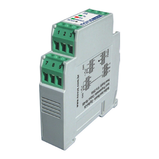
The universal analog input Modbus module DigiRail-2A is a remote
measuring unit with two configurable analog inputs. An RS485 serial
interface allows reading and configuring these inputs through the
communication network. It is appropriate for mounting on DIN 35
mm rails.
The inputs are electrically insulated from the serial interface and the
module supply. There is no electrical insulation between inputs.
There is also no electrical insulation between serial interface and
supply.
DigiRail-2A configuration is performed through the RS485 interface
by using Modbus RTU commands. The DigiConfig software allows
configuring all DigiRail features as well as performing its diagnostic.
DigiConfig offers features for detecting the devices present in the
Modbus network and for configuring the DigiRail-2A communication
parameters.
This manual provides instructions to install and connect the module.
The DigiConfig installer and the documentation regarding Modbus
communication for DigiRail-2A (DigiRail-2A Communication
Manual) are available at www.novusautomation.com.
ELECTRICAL INSTALLATION
INSTALLATION RECOMMENDATIONS
Input and communication signal conductors must pass through
•
the system plant separated from the electrical network
conductors. If possible, in grounded conduits.
The supply for the instruments must be provided from a proper
•
instrumentation network.
In control and monitoring applications, it is essential considering
•
what may occur if any of the system parts should fail.
We recommend the use of RC FILTERS (47Ω and 100nF,
•
series) in parallel with contactor and solenoid coils which are
close or connected to DigiRail.
ELECTRICAL CONNECTIONS
Figure 1 shows the necessary electrical connections. The terminals
1, 2, 3, 7, 8 and 9 are intended for the input connections, 5 and 6 for
the module supply and 10, 11 and 12 for the digital communication.
For obtaining a better electrical contact with the connectors, we
recommend the use of pin terminals at the conductor end. For direct
wire connection, the minimum gage recommended is 0.14 mm², not
exceeding 4.00 mm².
Be careful when connecting the supply terminals to
the DigiRail. If the positive conductor of the supply
source is connected, even momentarily, to one of the
communication connection terminals, the module
may be damaged.
NOVUS AUTOMATION
V1.0x F
Figure 1 –
Electrical connections
Table 1 shows how to connect the connectors to the RS485
communication interface:
Bidirectional data line.
Inverted bidirectional data
line.
Optional connection which
improves the communication
performance.
Table 1 – RS485 Connections
CONNECTIONS – INPUT 0-5 VDC / 0-10 VDC
For using the 0-5 Vdc and 0-10 Vdc input types, it is necessary to
switch the position of the inner module jumpers. To this end, the
module must be opened and jumpers J1 and J2 (input 1 and input 2,
respectively) must be changed due to the following options:
• For 0-5 Vdc and 0-10 Vdc input types, positions 1 and 2 must
be strapped.
• For all other input types, positions 2 and 3 must be strapped
(factory position).
Figure 2 –
Jumper for 0-5 Vdc and 0-10 Vdc input
Terminal 10
Terminal 11
Terminal 12
1/2
Advertisement
Table of Contents

Related Manuals for Novus DIGIRAIL-2A


Summary of Contents for Novus DIGIRAIL-2A
- Page 1 INSTRUCTION MANUAL − V1.0x F INTRODUCTION The universal analog input Modbus module DigiRail-2A is a remote measuring unit with two configurable analog inputs. An RS485 serial interface allows reading and configuring these inputs through the communication network. It is appropriate for mounting on DIN 35 mm rails.
- Page 2 DigiRail-2A CONFIGURATION INPUT SIGNAL MAXIMUM MEASURING RANGE 0 to 20 mV The user will receive the module perfectly calibrated. No adjustment will be required. The original configuration features the following -10 to 20 mV features: 0 to 50 mV Sensor thermocouple type J, Indication °C, Filter = 0...
Need help?
Do you have a question about the DIGIRAIL-2A and is the answer not in the manual?
Questions and answers