Advertisement
Quick Links
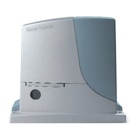
RobusKit 600/1000
For sliding gates weighing
up to 600 kg (RB600)
and up to 1000 kg (RB1000).
Electromechanical gear
motors with Nice BlueBUS
technology.
Versions with electromechanical
limit switch (RB600/RB1000)
and with inductive limit
switch (RB600P/RB1000P).
Version compatible with
the solar power system Solemyo.
Technical specifications
Power
(Vac 50/60 Hz)
Emergency power supply
Max. powered absorbed
Protection level
Nominal torque
Max. torque
Speed*
(m/s)
Max gate weight
Working temp.
(°C Min/Max)
Insulation class
Max work cycle *
(cycles/hour)
Dimension
(mm)
Weight
* This value changes according to the gate weight.
26
SYSTEMS FOR SLIDING GATES KIT PRICES 2010
User-friendly: the Nice BlueBUS
technology, enables to power and
control a maximum of seven couples
of photocells from the Moonbus series
using two wires only.
Practical: the control unit and PS124
buffer battery (optional) can be connected
by means of a simple connector and
can be housed directly inside the motor.
Advanced: RB600 and RB1000
are equipped with a temperature sensor:
adapt the motor power to the climatic
conditions and at the same time thermal
cut-out. A master/slave selection
automatically synchronises two motors.
This means it is possible to automate 2-leaf
sliding gates set opposite each other.
RB600/600P
RB1000/1000P
230
PS124
515
(VA)
44
(IP)
(Nm)
9
(Nm)
18
0.1 ÷ 0.3
0.09 ÷ 0.28
600
(kg)
-20 ÷ +50
1
40
330x303x210
11
(kg)
Dimensions
450
15
27
1000
330 mm
50
13
Intelligent: thanks to the obstacle
detection system and automatic
programming of the working times.
Motor absorption is monitored during
movement, self-diagnosis by means
of a flashing light. 8 programming levels.
Safe: acceleration and deceleration can
be adjusted at the beginning and end
of each opening and closing manoeuvre.
Sturdy: aluminium release handle
for easy opening.
Very quiet: gear motor on bearings.
210
Advertisement

Related Manuals for Nice RobusKit 600


Summary of Contents for Nice RobusKit 600
- Page 1 RobusKit 600/1000 For sliding gates weighing User-friendly: the Nice BlueBUS Intelligent: thanks to the obstacle technology, enables to power and detection system and automatic up to 600 kg (RB600) control a maximum of seven couples programming of the working times.
- Page 2 433.92 MHz, photocells designed with connector, without gear motor, with 2 channels for connection built-in transmitter incorporated control unit, 2 pcs via Nice BlueBUS 1 pc with electromechanical 1 pc limit switch, for gates up to 600 kg 1 pc...
- Page 3 For sliding gates Robus 600/600P 1000/1000P Instructions and warnings for the fitter Istruzioni ed avvertenze per l’installatore Instructions et recommandations pour l’installateur Anweisungen und Hinweise für den Installateur Instrucciones y advertencias para el instalador Instrukcje i uwagi dla instalatora Aanwijzingen en aanbevelingen voor de installateur...
- Page 4 Robus 600/600P 1000/1000P Table of contents: page Warnings Level one functions (ON-OFF functions) 7.2.1 Level one programming 7.2.2 Product description and applications (ON-OFF functions) Operating limits Level two functions 7.2.3 Typical system (adjustable parameters) List of cables Level two programming 7.2.4 (adjustable parameters) Installation...
- Page 5 Directive if used in the configurations foreseen in this instructions man- the conformity to the machine directive. ual and in combination with the articles present in the Nice S.p.a. prod- Please access “www.niceforyou.com” for further information, and guide- uct catalogue. If the product is not used in configurations or is used lines for risk analysis and how to draw up the Technical Documentation.
- Page 6 2) Product description and applications ROBUS is a line of irreversible electromechanical gearmotors for the ates with electric power. In the event of a power failure, the gearmo- automation of sliding gates. It is equipped with an electronic control tor can be released using a special key in order to move the gate unit and connector for the optional SMXI or SMXIS radiocontrol manually.
- Page 7 Table 3: limits in relation to the weight of the leaf RB600, RB600P RB1000, RB1000P Leaf weight (kg) % cycles Maximum speed % cycles Maximum speed allowed allowed Up to 200 100% V6 = Extremely fast 100% V6 = Extremely fast 200 ÷...
- Page 8 2.2) Typical system Figure 2 shows a typical system for automating a sliding gate using ROBUS Key-operated selector switch Secondary fixed edge (optional) Photocells on post Flashing light with incorporated aerial 10 ROBUS Photocells Main fixed edge (optional) 11 “Closed” stop bracket Main movable edge 12 Secondary movable edge (optional) “Open”...
- Page 9 3) Installation The installation of ROBUS must be carried out by qualified personnel in compliance with current legislation, standards and regulations, and the directions provided in this manual. • Make sure that the installation area enables the release of the gear- 3.1) Preliminary checks Before proceeding with the installation of ROBUS you must: motor and that it is safe and easy to release it.
- Page 10 If the rack is already present, once the gearmotor has been fastened, 7. Open the leaf up completely and place the first piece of the rack use the adjustment dowels as shown in Figure 8 to set the pinion of on the pinion.
- Page 11 3.4) Installation of the various devices If other devices are needed, install them following the directions provided in the corresponding instructions. Check this in paragraph “3.6 Description of electrical connections” and the devices which can be connected to the ROBUS in Figure 2. 3.5) Electrical connections Make a hole in the rubber membrane which is slightly smaller than the Only carry out electrical connections once the electric-...
- Page 12 3.6) Description of the electrical connections The following is a brief description of the electrical connections; for STOP see also Paragraph “7.3.2 STOP Input”. further information please read “7.3 Adding or Removing Devices” STEP-BY-STEP: input for devices which control Step-by-Step paragraph.
- Page 13 4.4) Recognizing the length of the leaf After recognizing the devices, L3 and L4 LED’s start flashing; the control unit must recognize the length of the gate. During this stage, the length of the leaf is measured from the closing limit switch to the opening limit switch. This measurement is required to calculate the decel- eration points and the partial opening point.
- Page 14 5.1) Testing Each component of the system, e.g. safety edges, photocells, emer- 6. Check the proper operation of all the safety devices, one by one gency stop, etc. requires a specific testing phase. We therefore rec- (photocells, sensitive edges, emergency stop, etc.) and check ommend observing the procedures shown in the relative instruction that the gate performs as it should.
- Page 15 7) Additional information Programming, personalisation and how to look for and deal with faults on the ROBUS will be dealt with in this chapter. 7.1) Programming keys The ROBUS control unit feature three keys that can be used to com- mand the control unit both during tests and programming.
- Page 16 7.2.2) Level one programming (ON-OFF functions). Level 1 functions are all factory set to “OFF”. However, they can be changed at any time as shown in Table 8. Follow the procedure careful- ly, as there is a maximum time of 10 seconds between pressing one key and another. If a longer period of time lapses, the procedure will fin- ish automatically and memorize the modifications made up to that stage.
- Page 17 Led di entrata Parametro Led (livello) Valore Descrizione 0,5 m Adjusts the measurement of the partial 1,5 m opening. Partial opening can be controlled Open Partially with the 2nd radio command or with 2,5 m “CLOSE”, if the “Close” function is present, this becomes “Open partially”.
- Page 18 7.2.5) Level one programming example (ON-OFF functions). The sequence to follow in order to change the factory settings of the functions for activating “Automatic Closing” (L1) and “Always close” (L3) have been included as examples. Tabella 11: Level one programming example Example Press the key [Set] and hold it down (approx.
- Page 19 7.3.2) STOP input STOP is the input that causes the immediate interruption of the • Two devices with 8,2KΩ constant resistance output can be con- manoeuvre (with a short reverse run). Devices with output featuring nected in parallel; if needed, multiple devices must be connected normally open “NO”...
- Page 20 7.3.5) ROBUS in “Slave” mode Properly programming and connecting, ROBUS can function in “Slave” mode; this type of function is used when 2 opposite gates need to be automated with the synchronised movement of the two leaves. In this mode ROBUS works as Master commanding the movement, while the second ROBUS acts as Slave, following the commands transmitted by the Master (all ROBUS are Masters when leaving the factory).
- Page 21 Tabella 14: ROBUS Slave programming independent from ROBUS Master Level one functions (ON-OFF functions) Level two functions (adjustable parameters) Stand-by Motor speed Peak Open Gate Indicator Output Slave Mode Motor force Error list On Slave it is possible to connect: •...
- Page 22 Control of the number of manoeuvres performed The number of manoeuvres performed as a percentage on the set limit can be verified by means of the “Maintenance warning” function. Fol- low the indications in table 17 for this control. Tabella 17: control of the number of manoeuvres performed Example Press the key [Set] and hold it down (approx.
- Page 23 7.6) Troubleshooting The table 19 contains instructions to help you solve malfunctions or errors that may occur during the installation stage or in case of fail- ure. Tabella 19: Troubleshooting Symptoms Recommended checks The radio transmitter does not control the gate Check to see if the transmitter batteries are exhausted, if necessary replace them and the LED on the transmitter does not light up The radio transmitter does not control the gate...
- Page 24 7.7.1) Flashing light signalling During the manoeuvre the flashing light FLASH flashes once every second. When something is wrong the flashes are more frequent; the light flashes twice with a second's pause between flashes. Tabella N°21: FLASH flashing light signalling Quick flashes Cause ACTION...
- Page 25 The following optional accessories are available for ROBUS: For information on the complete range of accessories, refer to the • PS124 PS124 24 V Buffer battery - 1,2Ah with integrated charger Nice s.p.a. product catalogue. battery. • SMXI or SMXIS 433.92MHz Radio receiver with digital Rolling code.
- Page 26 8) Technical characteristics Nice S.p.a., in order to improve its products, reserves the right to modify their technical characteristics at any time without prior notice. In any case, the manufacturer guarantees their functionality and fitness for the intended purposes. All the technical characteristics refer to an ambient temperature of 20°C (±5°C)
- Page 27 This operation antee high levels of safety and security. They are has been carefully designed by Nice to make it equipped with detection devices that prevent move- extremely easy, without any need for tools or physical ment if people or objects are in the way, guaranteeing exertion.
- Page 28 Nice products. You will get the the control is released the gate will stop. services of a specialist and the most advanced pro- ducts available on the market, superior performances and maximum system compatibility.
- Page 30 Il sottoscritto Lauro Buoro in qualità di Amministratore Delegato, dichiara sotto la propria responsabilità che il prodotto: The undersigned Lauro Buoro, managing director, declares under his sole responsibility that the following product: Nome produttore: NICE s.p.a. Manufacturer’s name Indirizzo Via Pezza Alta 13, 31046 Z.I. Rustignè, Oderzo (TV) Italia...
- Page 31 Shanghai Tel. +39.06.72.67.17.61 Tel. +33.(0)4.42.62.42.52 info@es.niceforyou.com Tel. +86.21.575.701.45/46 Fax +39.06.72.67.55.20 Fax +33.(0)4.42.62.42.50 Fax +86.21.575.701.44 inforoma@niceforyou.com info@cn.niceforyou.com www.niceforyou.com Nice Gate is the doors and gate automation division of Nice Nice Screen is the rolling shutters and awnings automation division of Nice...
Need help?
Do you have a question about the RobusKit 600 and is the answer not in the manual?
Questions and answers
При отключении электроэнергии ворота должны открыться и остаться в открытом положнии, при включении электроэнергии включиться в рабочий режим. Пошаговая инструкция.
The Nice RobusKit 600 does not explicitly mention a built-in backup feature to keep the gate open during a power outage. However, to achieve this functionality, follow these steps:
1. Install a Backup Battery: If the system supports a backup battery, install it to ensure operation during power loss.
2. Use an Uninterruptible Power Supply (UPS): Connect the control unit to a UPS to maintain power.
3. Configure the Control Unit: If the system allows, program it to remain open in case of power failure.
4. Manual Release: If no backup power is available, manually release the motor to open the gate and secure it in place.
5. Resume Normal Operation: When power is restored, re-engage the motor and test normal functionality.
For detailed electrical connections and settings, refer to the manual sections on power supply and safety features.
This answer is automatically generated