
Subscribe to Our Youtube Channel
Related Manuals for CTC Union PMX1500 Series


Summary of Contents for CTC Union PMX1500 Series
- Page 1 PMX1500 Series Monitoring System PMX1500 Series Monitoring System 4 Sensor Inputs 4 Sensor Inputs Product Manual Product Manual...
- Page 2 Table of Contents • Introduction . . . . . . . . . . . . . . . . . . . . . . . . . . . . . . . . . . . . . . . . . . . . . . . . . . . . . . . . . . . . . . . . . . .3 •...
- Page 3 . PMX1500 The PMX1500 Series system monitors a machine’s condition based on its level of vibration . The system can be integrated into a circuit to shut down a machine when preset vibration levels are reached . The system detects high vibration energy sensed via the input accelerometers and actuates relays based on alert and alarm set points .
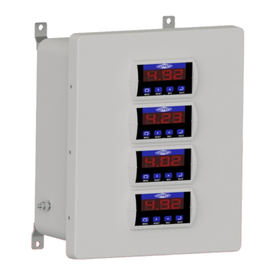
- Page 4 Product Dimensions Front View Side View Figure 1. Dimensions Vibration Level Displays Figure 2. Diagram...
- Page 5 . CTC does not recommend putting holes in the top of the enclosure due to access and moisture concerns . Mounting Holes 0 .33 in ./8 .38 mm Figure 3. PMX1500 Series Rear View...
- Page 6 Conduit Entry If you are running conduit to your enclosure, ensure the conduit cable entry enters from the bottom of the enclosure when mounted . Note: To ensure moisture will not flow into the enclosure, a hole should be drilled at the lowest point in the conduit to provide drainage for any moisture .
- Page 7 Grounding Ensure the shield ground wire on the PMX1500 Series enclosure is grounded to earth ground . A. Mounting to Earth Ground When mounting PMX1500 Series enclosures to earth ground (such as an I-Beam), mount the shield ground wire using a mounting bolt through one of the mounting brackets on the enclosure .
- Page 8 B. Mounting to Non-Grounded Structure When mounting the PMX1500 enclosure to a non-grounded structure, ensure the shield ground wire or customer-supplied ground wire is tied to a source of earth ground . Figure 6. Ground Wire Placement...
- Page 9 Electrical Connectons Cables enter and exit the enclosure through conduit fittings or cord grips on the bottom of the unit . All input and output wiring is connected to the terminal blocks inside the unit . Inputs are routed through a 1 .5 in . conduit fitting or cord grips (1 per channel), output wiring is routed through a 1 .5 in .
- Page 10 Wiring Inputs and Outputs When purchasing a PMX1500 Series enclosure, CTC will wire the displays to the internal terminal blocks prior to shipment . Use the following pages to determine the correct way to wire sensors into the system .
- Page 11 Wiring Outputs Wiring Outputs Display Terminal Terminal Block Block Cable Position Position Color Destination Blue Common Out Middle Brown Normal Closed Bottom Yellow Normal Open...
- Page 12 Wiring Power In order to safely supply power to the relays, the PMX1500 features a circuit breaker . Below is the wiring configuration to bring live power into the enclosure . Terminal Wire Wire Color Position Ground Green Neutral Power White Middle Live Power...
- Page 13 Configuring Relays The input to the internal controller comes from the sensor or vibration transmitter . They are built with a specific full-scale range and frequency band . The full-scale range of the transmitters must be known for the controllers to display the correct vibration value .
- Page 14 LOC Relay (Relay 2) when the vibration level reaches 0 .65 IPS-pk . To reset the LOC relays, the vibration level must fall below the reset point of 0 .60, then press the ACK for relay two . Once the vibration level falls below 0 .30, press the ACK to reset Relay 1 .
Need help?
Do you have a question about the PMX1500 Series and is the answer not in the manual?
Questions and answers