Table of Contents
Advertisement
Quick Links
Installation, Operation & Maintenance Manual
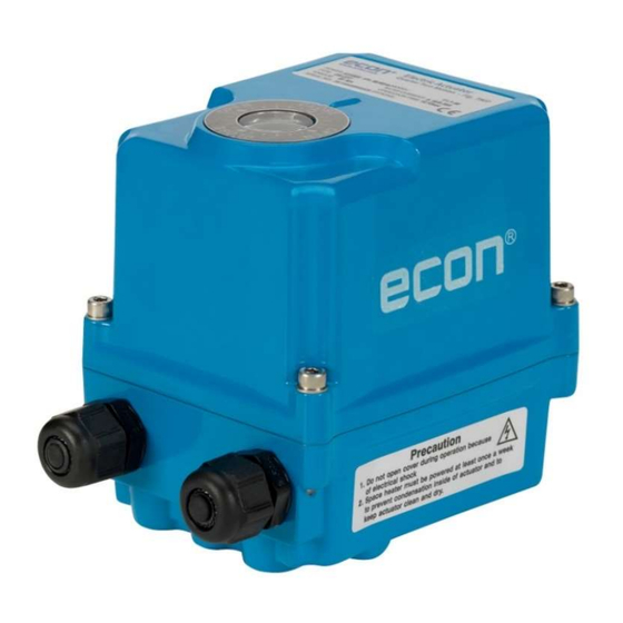
Fig. 7907 ELA60
IP67 (optionally IP68)
Scan for manual
Installation, Operation and Maintenance Manual for actuator: ELA60
Website: www.hkcon.co.k r
ECON actuator Fig 7907, type ELA60
Rev.14 – September 12, 2024
ECON ELECTRIC ACTUATOR
Fig. 7907, type ELA60
Fig. 7907 ELA60-Ex
ǁ 2G Ex db IIB T4 Gb
Small & Compact quarter turn actuator
Mechanical position indicator
High output torque
Multi mounting base
Manual override
Proven Quality since 1892
www.eriks.com
Advertisement
Table of Contents

Related Manuals for Econ 7907 ELA60


Summary of Contents for Econ 7907 ELA60
- Page 1 Small & Compact quarter turn actuator Mechanical position indicator High output torque Multi mounting base Manual override Scan for manual Installation, Operation and Maintenance Manual for actuator: ELA60 Website: www.hkcon.co.k r ECON actuator Fig 7907, type ELA60 www.eriks.com Rev.14 – September 12, 2024...
-
Page 2: Table Of Contents
5. FIELDBUS COMMUNICATION PROTOCOL (Optional) 5.1. ModBus Controler 5.2. Specification 6. OPERATION 6.1. Electrical Connections and Preliminary Test 7. MAINTENANCE 7.1. M ain ten an ce 7.2. Tools ECON actuator Fig 7907, type ELA60 www.eriks.com Rev.14 – September 12, 2024... - Page 3 8.2. The actuator is supplied with power but does not operate 8.3. Actuator runs erratically 8.4. Optional Equipment 9. DIMENSIONS 9.1. ELA60 On/Off Typ e 9.2. ELA60 PCU Type 9.3. ELA60-Ex-version On/Off type WIRING DIAGRAMS ECON actuator Fig 7907, type ELA60 www.eriks.com Rev.14 – September 12, 2024...
-
Page 4: Introduction
CAUTION: Directs the user’s attention to general precautions that, if not followed, could result in personal injury and/or equipment damage. Note: Information in this manual is critical to the user’s understanding of the actuator’s installation and operation ECON actuator Fig 7907, type ELA60 www.eriks.com Rev.14 – September 12, 2024... -
Page 5: Product Identification
2.1.3 Certification ATEX : EPS 19 ATEX 1 087 X II 2G Ex db IIB T4 Gb IECEx : EPS 19.0047X Ex db IIB T4 Gb ECON actuator Fig 7907, type ELA60 www.eriks.com Rev.14 – September 12, 2024... -
Page 6: Initial Inspection
Storage must be off the floor, covered with a sealed dust protector. GENERAL INFORMATION AND FEATURES General Information ECON ELA60 electric actuators are designed to provide reliable and efficient operation of 90 degree quarter turn valves, such as Ball and Butterfly valves, etc. Standard Technical Data 3.1.1... -
Page 7: Additional Technical Data
The manual override system of the ELA60-Ex d actuators can be operated by using a 4mm Allen key only. Turn the manual override (Allen key) until the valve reaches the required position (turn clockwise to fully open and counter-clockwise to fully close). ECON actuator Fig 7907, type ELA60 www.eriks.com Rev.14 – September 12, 2024... -
Page 8: Lubrication
Internal Parts for Standard Models Internal Parts ELA60 Motor Indicator Open Limit Switch Close Limit Switch Additional Open Limit Switch Additional Close Limit Switch Potentiometer Unit (Optional) Terminal Heater Capacitor ECON actuator Fig 7907, type ELA60 www.eriks.com Rev.14 – September 12, 2024... -
Page 9: Installation
Actuator Mounting Note: 1. Prior to mounting, the part-turn actuator must be checked for any damage 2. Damaged parts must be replaced by genuine spare parts ECON actuator Fig 7907, type ELA60 www.eriks.com Rev.14 – September 12, 2024... -
Page 10: Actuator Mounting Base Details
The ISO5211 bolt patterns are provided for actuator mounting. The actuator drive bushing can be replaced or removed for machining easily. CAUTION: Do not attempt to work on your ECON actuator without first shutting off the power supply. Do not attach ropes for lifting purposes to the manual override device. -
Page 11: Limit Switch Setting
Rotate the OPEN cam CCW until the limit switch ‘clicks’ (see Figure 2 below) Tighten the set screw with the Allen key DANGER: HAZARDOUS VOLTAGE. Make sure all incoming power is disconnected before setting the limit switches ECON actuator Fig 7907, type ELA60 www.eriks.com Rev.14 – September 12, 2024... -
Page 12: Setting Potentiometer (Optional)
Ambient Humidity 90% RH Max (Non-condensing condition) Dielectric Strength 1500V AC 1 Min (Input to output to power ground) Insulation Resistance Above 500V DC 30MΩ Vibration 10g, 0~34Hz ECON actuator Fig 7907, type ELA60 www.eriks.com Rev.14 – September 12, 2024... -
Page 13: Calibration Of Zero And Span - Cpt
(counter- clockwise rotation). When the actuator is in the fully open position, adjust the SPAN open setting on the CPT board until a reading of 20mA is achieved. ECON actuator Fig 7907, type ELA60 www.eriks.com Rev.14 – September 12, 2024... -
Page 14: Proportional Control Units - Pcu (Optional)
However, we strongly recommend that input power, signal input selection and dip switches are to be verified prior to the actuator start up. Settings the PCU functions are shown in paragraph 4.6.3 and 4.6.4. ECON actuator Fig 7907, type ELA60 www.eriks.com Rev.14 – September 12, 2024... -
Page 15: Pcu-D Proportional Control Unit Direct Current
Settings the PCU functions are shown in paragraph 4.6.3 and 4.6.4. CAUTION: HAZARDOUS VOLTAGE. Turn off all power before setting the actuator. ECON actuator Fig 7907, type ELA60 www.eriks.com Rev.14 – September 12, 2024... -
Page 16: Led Signal Indication
2 - 10V DC 0 - 5V DC 0 - 10V DC 60 Hz 50 Hz Note: If not specified, the factory setting of the input signal is 4 - 20mA. ECON actuator Fig 7907, type ELA60 www.eriks.com Rev.14 – September 12, 2024... - Page 17 SW8-1 “ON” , SW8-1 “ON” & SW7-3 “OFF” 1 – 5V DC Output Signal Switch If not specified, the factory setting of the output signal is 4 - 20mA. Note: ECON actuator Fig 7907, type ELA60 www.eriks.com Rev.14 – September 12, 2024...
- Page 18 Signal: 4.3~4.0mA Fully Closed Auto-Full Switch (Switch 3) On (up) Signal: 19.7~20.0mA Fully Open Signal: 4mA Fully Closed Auto-Full Switch (Switch 3) Off (down) Signal: 20mA Fully Open ECON actuator Fig 7907, type ELA60 www.eriks.com Rev.14 – September 12, 2024...
-
Page 19: Auto Setting
2 seconds. In both cases, the yellow LED will be lit off to indicate the termination of the Manual Operation Mode. Note: During the Manual Operation mode, the input signal is ignored. ECON actuator Fig 7907, type ELA60 www.eriks.com Rev.14 – September 12, 2024... -
Page 20: Delay Time
Turning the Delay Time Dial in clockwise direction will increase the delay time (Range 0.05 to 7.5 seconds). Dial 0.05 Dial ECON actuator Fig 7907, type ELA60 www.eriks.com Rev.14 – September 12, 2024... -
Page 21: Pcu-Eb - Proportional Control Unit Alternating Current (2020 Version)
Please be noted that two PCU Alternating Current PCB’s are available. Check the markings on the PCB before you start working on the settings. The instructions below are only applicable to the PCU-EB PCB. PCU-EB-V1.5 ECON actuator Fig 7907, type ELA60 www.eriks.com Rev.14 – September 12, 2024... - Page 22 X, Y & Z, 10g (6g based on RMF), Frequency: 0.2~34Hz, Time: 30 minutes A) LED Signal Indication Signal Open Blue Power or Auto Close Green Manual or Fault Yellow ECON actuator Fig 7907, type ELA60 www.eriks.com Rev.14 – September 12, 2024...
-
Page 23: Selecting Input Signal
By Dip Switch Note: 4-20mA is the standard factory setting for the output signal of this PCU. CAUTION: “(1) Selection of input signal” ZERO SWITCH (SW7.3) Usage Notes ECON actuator Fig 7907, type ELA60 www.eriks.com Rev.14 – September 12, 2024... - Page 24 : 0.25s increase per step (0.25 ~ 1 sec) ③ Step 5 ~ 15 : 0.50s increase per step (2.5 ~ 7.5 sec) ④ Factory setting : “2” ECON actuator Fig 7907, type ELA60 www.eriks.com Rev.14 – September 12, 2024...
-
Page 25: Manual Mode
Note: The Auto Setting command is cancelled automatically when any button (Zero, Span or A-scan) is pressed during the Auto Setting mode. ECON actuator Fig 7907, type ELA60 www.eriks.com Rev.14 – September 12, 2024... -
Page 26: Reverse Mode
ZERO (FULL CLOSE) Signal, SPAN (FULL OPEN) Signal for changing the Signal ZERO (FULL CLOSE) Signal SETTING Range: Generally 3 ~ 8 mA DC SPAN (FULL OPEN) Signal SETTING Range: Generally 16 ~ 21mA DC ECON actuator Fig 7907, type ELA60 www.eriks.com Rev.14 – September 12, 2024... - Page 27 Check if the RED and GREEN LED are switched on together and wait until RED LED ⑪ switches off. Put dip switch No. 4 back to OFF (SW7). ⑫ ECON actuator Fig 7907, type ELA60 www.eriks.com Rev.14 – September 12, 2024...
- Page 28 Input signal initialization error Auto Setting initialization error Input signal error Motor backlashing Command signal select switch error POTENTIOMETER Open position error Close position error Limit switch error ECON actuator Fig 7907, type ELA60 www.eriks.com Rev.14 – September 12, 2024...
-
Page 29: Ac/Dc Multi-Board (Optional)
“ON” and #2 switch turn “OFF” “OFF” and #2 switch turn “ON” Note: Don’t operate both switches #1 and #2 at the same time. It may damage the board ECON actuator Fig 7907, type ELA60 www.eriks.com Rev.14 – September 12, 2024... -
Page 30: Fieldbus Communication Protocol (Optional)
Supported Baud Rates: 1200, 2400, 4800, 9600, 19200, 38400, 57600, 115200 Supported Parity Bit: Odd, Even, None Supported Stop Bit: 1, 2 For more detail information, please refer to separate ModBus operation manual. ECON actuator Fig 7907, type ELA60 www.eriks.com Rev.14 – September 12, 2024... -
Page 31: Operation
HAZARDOUS VOLTAGE. Electrical power must not be connected until all wiring and limit switch adjustments have been completed. Once the power is supplied to the unit, precautions must be taken if the cover is not mounted on the actuator. ECON actuator Fig 7907, type ELA60 www.eriks.com Rev.14 – September 12, 2024... -
Page 32: Maintenance
Multi-meter (AC, DC, Resistance) x 1 PCU Board option: DC Signal Generator (4 – 20mA DC) x 1 PCU & CTU Board Option: 1mA Ammeter (0 – 25mA) ECON actuator Fig 7907, type ELA60 www.eriks.com Rev.14 – September 12, 2024... -
Page 33: Trouble Shooting
Verify that coupler/bracket is correctly installed and may not block the actuator rotation. Actuator runs erratically Check the ambient temperature Verify that the duty cycle has not been exceeded Check the position of manual override lever ECON actuator Fig 7907, type ELA60 www.eriks.com Rev.14 – September 12, 2024... -
Page 34: Optional Equipment
Check the board for any damage 2) Current Position Transmitter Verify the input signal Check the configuration of the dip switches Check the board for any damage ECON actuator Fig 7907, type ELA60 www.eriks.com Rev.14 – September 12, 2024... -
Page 35: Dimensions
Installation & Operation Manual Proven Quality since 1892 DIMENSIONS ELA60 On/Off Type ECON actuator Fig 7907, type ELA60 www.eriks.com Rev.14 – September 12, 2024... -
Page 36: Ela60 Pcu Type
Installation & Operation Manual Proven Quality since 1892 ELA60 PCU Type (Optional) ECON actuator Fig 7907, type ELA60 www.eriks.com Rev.14 – September 12, 2024... -
Page 37: Ela60-Ex-Version On/Off Type
Installation & Operation Manual Proven Quality since 1892 ELA60-Ex-version On/Off Type NOTE : For more information regarding this product, please contact your nearest supplier on www.eriks.com ECON actuator Fig 7907, type ELA60 www.eriks.com Rev.14 – September 12, 2024... -
Page 38: Wiring Diagrams
Installation & Operation Manual Proven Quality since 1892 WIRING DIAGRAMS ECON actuator Fig 7907, type ELA60 www.eriks.com Rev.14 – September 12, 2024... - Page 39 Installation & Operation Manual Proven Quality since 1892 ECON actuator Fig 7907, type ELA60 www.eriks.com Rev.14 – September 12, 2024...
- Page 40 Installation & Operation Manual Proven Quality since 1892 ECON actuator Fig 7907, type ELA60 www.eriks.com Rev.14 – September 12, 2024...
- Page 41 Installation & Operation Manual Proven Quality since 1892 ECON actuator Fig 7907, type ELA60 www.eriks.com Rev.14 – September 12, 2024...
- Page 42 Installation & Operation Manual Proven Quality since 1892 ECON actuator Fig 7907, type ELA60 www.eriks.com Rev.14 – September 12, 2024...
- Page 43 Installation & Operation Manual Proven Quality since 1892 ECON actuator Fig 7907, type ELA60 www.eriks.com Rev.14 – September 12, 2024...
- Page 44 Installation & Operation Manual Proven Quality since 1892 ECON actuator Fig 7907, type ELA60 www.eriks.com Rev.14 – September 12, 2024...
- Page 45 Installation & Operation Manual Proven Quality since 1892 ECON actuator Fig 7907, type ELA60 www.eriks.com Rev.14 – September 12, 2024...
- Page 46 Once the power is supplied to the unit, precautions must be taken if the cover is not mounted on the actuator. If you have questions about this product, Please contact the nearest ECON distributor. You can find them on www.eriks.com...
Need help?
Do you have a question about the 7907 ELA60 and is the answer not in the manual?
Questions and answers